IMPULSE CAR FOR HOME
In general, a voltage converter or converter is an electrical device capable of converting one level or type of this parameter to another.
As a rule, when talking about voltage converters, we mean converters operating in alternating current circuits (AC/AC). In other cases, these devices are called direct-voltage converters (DC/DC) or inverters (DC/AC or AC/DC).
Devices for voltage conversion are found everywhere in practice. They are distinguished and classified according to various criteria.
By purpose, converters are divided into:
DC-DC converters
, namely:
- regulators;
- linear stabilizers.
AC voltage converters
. This category includes:
- transformers of various types;
- regulators;
- signal shape and frequency converters.
Inverters for converting direct voltage into alternating voltage and vice versa. The group of inverters also includes:
- rectifiers;
- pulse stabilizers.
In addition, experts classify power supplies into a separate category, each of which contains some kind of voltage converter. They are:
- built-in power supplies for various types of equipment;
- small-sized adapters (chargers) designed for power supply (charging) of mobile phones, electronic gadgets and devices.
PULSE VOLTAGE CONVERTERS
Pulse converters are used in cases where it is necessary to convert one voltage level to another. Most often they are assembled on the basis of inductive or capacitive energy storage devices. They are distinguished from other power sources by their high level of efficiency, reaching 95% in some cases.
Schematic electrical circuits of pulse converters are made using 4 elements:
- switching element;
- energy storage (inductor, inductor, capacitors);
- blocking diode;
- a capacitor connected in parallel with a load resistance.
Combinations of the listed components can form any type of pulse converter.
The output voltage is determined by the width of the pulses that control the switching element. This creates a reserve of energy in the inductor. Stabilization is realized through feedback, that is, the pulse width changes depending on the value of the output voltage.
To create high-frequency currents, converters assembled using oscillatory circuits are used. In this case, the direct current voltage supplied to the alternating voltage generator (multivibrator, trigger) is also the supply voltage. The output pulses are usually rectangular in shape.
The resulting alternating voltage can be increased, decreased, etc. In addition, it is easy to rectify and obtain the desired polarity. To do this, use the appropriate connection of diodes, and the rectifier is assembled, for example, using a bridge circuit.
The voltage at the output of pulse converters must be stabilized. For this purpose, various types of stabilizers are used (pulse or linear). True, due to low efficiency, the latter are rarely used.
As for pulse stabilizers, they use pulse width or frequency pulse modulation in their work. In the first case, the duration changes; in the second, the frequency of the pulses changes. There are devices with a combined stabilization method.
Voltage doubler
Figure 1 shows the LED power supply circuit using the principle of doubling the supply voltage. The low-frequency pulse generator is made using transistors of different structures: KT361 and KT315.
The pulse repetition rate is determined by the time constant R1C1, and the duration of the pulses is determined by the time constant R2C1. From the output of the generator, short pulses through resistor R4 are supplied to the base of transistor VT3, the collector circuit of which includes a red LED HL1 (AL307KM) and a germanium diode VD1 of type D9.
A high-capacity electrolytic capacitor C2 is connected between the output of the pulse generator and the connection point between the LED and the germanium diode.
During a long pause between pulses (transistor VT2 is closed and does not conduct current), this capacitor is charged through diode VD1 and resistor R3 to the voltage of the power source. When generating a short pulse, transistor VT2
opens. The negatively charged plate of capacitor C2 is connected to the positive power bus. Diode VD1 is turned off. The charged capacitor C2 is connected in series with the power source.
The total voltage is applied to the LED circuit - the emitter - collector junction of transistor VT3. Since transistor VT3 is unlocked by the same pulse, its emitter-collector resistance becomes small.
Thus, almost double the supply voltage (excluding minor losses) is briefly applied to the LED: a bright flash follows. After this, the process of charging and discharging capacitor C2 is periodically repeated.
Rice. 1. Schematic diagram of a voltage doubler for powering an LED.
Since LEDs can operate at short-term pulse currents tens of times higher than the rated values, the LED does not become damaged.
If it is necessary to increase the reliability of LED emitters with low-voltage power supply and expand the supply voltage range upward, a current-limiting resistor with a resistance of tens or hundreds of Ohms should be connected in series with the LED.
When using an LED of the AL307KM type with a voltage of the beginning of a barely noticeable glow of 1.35 ... 1.4 V and a voltage at which, without limiting resistance, the current through the LED is 20 mA, 1.6 ... 1.7 V, the operating voltage of the generator shown in the figure 1, is 0.8... 1.6 V.
The range limits are determined experimentally in the same way: the lower one indicates the voltage at which the LED begins to glow, the upper one indicates the voltage at which the current consumed by the entire device is approximately 20 mA, i.e. under the most unfavorable operating conditions does not exceed the maximum current through the LED and, at the same time, the converter itself.
As noted earlier, the generator (Figure 1) operates in a pulsed mode, which is, on the one hand, a disadvantage of the circuit, but on the other hand, an advantage, since it allows you to generate bright flashes of light that attract attention.
The generator is quite economical, since the average current consumed by the device is small. At the same time, the circuit must use a low-voltage, but rather bulky, high-capacity electrolytic capacitor (C2).
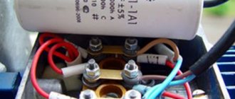
AUTOMOBILE VOLTAGE CONVERTERS
With the increase in the number of cars, the need to use various household appliances during their operation, including those operating on 220V alternating voltage, has increased.
For this purpose, automobile inverters were developed, with the help of which the constant voltage from a car battery +12 V (cars) or +24 V (trucks) is converted into alternating 220 V. You can connect an electric razor or electric drill to them, charge a laptop, etc.
A car inverter is a voltage generator whose shape is close to a sinusoid. In this case, the current at the output of the device does not depend on the value of the current at the input and it can be adjusted practically from zero to maximum. In the same way, it is theoretically possible to adjust the frequency and voltage.
In a simplified way, the electrical circuit of a car converter can be represented as a transformer, the primary windings of which are supplied with voltage through thyristor switches. Alternately turning on the windings, the thyristors create alternating current at the output of the transformer.
In this case, a modified (stepped) sinusoid is formed, but this does not in any way affect the performance of most household appliances.
Converters for use in cars have a fairly high efficiency, which reaches 90%, which indicates a fairly high quality of the resulting sinusoid.
During the operation of the device, the consumer has the opportunity to choose one of three operating modes:
- An operating mode that ensures long-term operation of the inverter at rated power.
- Overload mode, which allows you to get significantly more power from the device than when operating in normal mode. However, in this mode the inverter should not operate for more than 30 minutes.
- The starting mode is used when it is necessary to obtain instant power under high load (starting an electric motor, etc.).
Attention! When operating the inverter, it is not recommended to constantly turn it on at maximum power. It is necessary to select its operating mode based on the load size.
When choosing a converter for a car, the main attention should be paid to its power. Its value must obviously be greater than the power of the connected devices. In addition, the type of electrical appliances connected is also important. If you plan to connect devices that consume significant currents when starting up to a car inverter, then you need to purchase a device with the appropriate power (from 300 to 2000 W).
Scheme of a powerful high-voltage voltage converter for 2 kV
How to make a high-voltage DC-DC converter with your own hands? Dedicated to those who find not only disadvantages, but also advantages in high voltageHigh voltage voltage converter designed to receive direct or alternating current from a low-voltage high-voltage source (up to tens of thousands of volts). The main requirement that determines the operating principle of such converters is the ability to effectively transfer useful power to the output, ensuring maximum efficiency.
Single-cycle converters make it possible to obtain high output voltages at minimal cost, but subject to relatively low load power. The reason is the rather low efficiency of single-cycle devices. To begin with, as an example, I will give the simplest circuit diagram of a high-voltage converter module produced by our unassuming Chinese friends.
Fig. 1 The simplest high-voltage voltage converter
The primary winding is located under the secondary. It is wound on a ferrite rod with high magnetic permeability and contains several turns of 0.8...1 mm wire. The number of turns of the secondary winding is several thousand. Without load, the circuit consumes significant current from the power source (2...3A). This is a consequence of the long edges at the transistor's gate (due to its high capacitance combined with the high output impedance of the NE555), as well as the low inductance of the primary winding of the transformer. Of course, with such a transformer the circuit will not produce any 20,000 volts, a maximum of 3...4 kV with a power of several watts. Conclusion - this version is NOT RECOMMENDED for purchase or repetition! However, in the case of using a line transformer for a CRT with a built-in multiplier circuit and a resonant capacitor in its primary winding, it is still possible to obtain the required 20 kV. This is exactly the scheme we looked at on the page – Link to page.
A push-pull converter made according to the circuit of a symmetrical inductive multivibrator will have slightly better power characteristics. This scheme is surprisingly popular among shocker builders of all stripes and is the basis of the famous “evil shocker” from lamazoid, as well as many other developments based on similar motives. Now, let's take a look at the circuit of such a converter with the values of the elements and measurements of current consumption carried out by participants in one of the HV forums: Aleksandr_Sokolov and urez83.
Fig.2 Push-pull high-voltage voltage converter
The main disadvantage of such circuits is: 1. Extremely high current consumption (and therefore low efficiency) of the converter, associated with prolonged operation of the key transistors in linear mode, and 2. Incomplete use of the power supply voltage.
A slightly modified version - the Mazilli ZVS Flyback driver, which we described in detail on the page - link to the page, although it reduces these disadvantages, it is far from completely.
The push-pull boost converter described below is made using common digital elements and has an efficiency exceeding 90%. At the same time, it effectively and fully uses the voltage of the power supply, which, compared to the Mazilli ZVS Flyback driver, makes it possible to significantly reduce the number of turns of the secondary winding of the transformer.
Fig.3 Powerful push-pull high-voltage voltage converter with high efficiency
The master oscillator is made on element DD1.1. The shape of its output signal is close to a square wave, and the frequency of 30 kHz is set by selecting (if necessary) the value of capacitor C1.
Chains D1, R3, C3 and D2, R2, C2 – form a delay (Dead Time) for switching output transistors T5, T6 (about 4 μs), guaranteeing that the transistor of one arm will begin to open only after the transistor of the other arm is completely closed .
Antiphase signals coming from outputs DD1.3 and DD1.4 are amplified in current by cascades T1, T2 and T3, T4 and then go to the gates of powerful output transistors having significant input capacitances (about 3000 pF). These cascades are necessary to obtain control pulses with steep edges, which contributes to fast switching of transistors and, in turn, increasing the efficiency of the device.
The converter parameters are sensitive to the inductance values of the primary windings of the transformer. Optimal characteristics correspond to inductances of 20...30 μH. With smaller values, the efficiency of the converter decreases, with larger values, the power drops.
When using the elements indicated in the diagram, a clock generator frequency of 30 kHz and an inductance of the primary windings of 20 μH, the output power of the converter is about 300 W, and the no-load current consumption is 500 mA. At 30 µH the consumption drops to 300 mA. The power of the converter can be increased by selecting more powerful output transistors or by connecting pairs of field switches of the specified type in parallel. In this case, in order to avoid deterioration in efficiency, it is necessary to double the values of capacitors C2, C3.
Capacitor C8 is designed to limit the current of the output transistors in the event of a short-term short circuit at the output. At the rating indicated in the diagram, the transistor current during a short circuit will not exceed 30A.
Elements R5, C4, R7, R8 serve to eliminate through currents through the output transistors at the moment the voltage is applied. If the converter is planned to be used as a driver to obtain voltages of tens of kilovolts, then protective zener diodes of 15...18 V should be connected in parallel with R7, R8.
The transformer is wound on a toroidal ferrite core EPCOS R 29.5×19.0×14.9 No. 87 with an overall power of 297 W. The number of turns is indicated in the diagram. Since this converter can be used to generate a wide range of output voltages: from tens of volts to tens of kilovolts, it does not make much sense to pay attention to a detailed description of the transformer design. For high-voltage purposes, both a factory line transformer from cathode ray tubes of televisions and a transformer made on an armored core are perfect. For lower voltages, the optimal choice would be a pulse transformer on a ferrite ring, the calculation method of which we discussed in detail on the page - link to the page. It is important to understand that the presence of a gap in the cores for push-pull converters is not only not beneficial, but also harmful due to a decrease in its magnetic permeability, and, accordingly, the inductance of the primary windings, which inevitably leads to a decrease in the efficiency parameter.
The permissible voltages of the rectifier diodes and capacitor C8 must be 1.5 times higher than the maximum output voltage, C9 - at least not lower. It is also necessary to ensure that the frequency range of the rectifier diodes fits within the frequency of the clock generator. If the diodes can only operate up to 20 kHz, then the generator frequency must also be reduced to this value, and the inductance of the primary windings must be calculated based on values of 30...40 μH.
ATTENTION!!! Working with high voltage is extremely dangerous to the life and health of the body. Therefore, Vpayaem.ru strongly does not recommend practicing in this area in the absence of special knowledge and relevant experience. All information posted on this page is intended for informational purposes only - remember this, dear gentlemen and ladies, and do not say that you were not warned!
Frequency converters SYN-Drive series
Frequency converters of the SYN-Drive series are devices that control the operation of electric motors with a rated power from 200 to 17500 kW at a voltage of 3,6,10 kV, developed and produced at a production facility located in Germany, engineering and design solutions are implemented through the joint efforts of engineers of JSC Elektromash " and SYNTRONIC.
Converters of this series are controlled on the basis of pulse-width modulation (PWM), have an increased overload capacity, a self-testing function, and a high level of efficiency (96-98%). The special design of the modular housing allows the devices to be used in the most aggressive conditions - from a coal mine with the presence of conductive dust in the air to the far north, where temperatures reach -80C. (RF) - SYNTRONIC (Germany) 1. High efficiency of electric motors: high efficiency, reduced harmonic losses, high power factor. 2. Reliability: fiber optic communication, use of components from leading manufacturers, factory testing on a load stand, certification and comprehensive testing at the Customer’s site. 3. Trouble-free operation, maintaining the operation of the electric motor during a short-term de-energization of the object and a voltage drop. 4.Reducing energy costs by up to 30%, water costs by 10%; 5.Minimum service life of at least 20 years. Reduced repair and maintenance costs due to the absence of water hammer in the pipeline and smooth operation of the drive mechanism;
Scope of application of modern industrial high-voltage frequency converters: - Oil and gas and chemical industries (compressor units, pumping units, extruders, mixers, processing machines); — Ferrous and non-ferrous metallurgy (machine tools, conveyors, pumps, gas supply fans and heating furnaces); — Energy and electricity generating enterprises (network pumps, feed pumps, fans); — Coal industry (lifts, pumps, fans, conveyors, furnaces); — Housing and communal services (pumps and pumping stations, fans, circulation pumps for heating systems); — Lifting and transport equipment (cranes, elevators, cable cars); — Light industry (pumps, fans, production lines); — Military industry (fans).
By purchasing high-voltage frequency converters from the RUSELT Group, you receive a full range of services, including installation consultations, commissioning, personnel training and technical support.
Design
Functionally, the cell consists of two parts: the first includes a chopper, an inverter and two three-phase contactors; it is this part that is installed in a rack, which ensures ease of maintenance and high maintainability. The appearance of the board with the indicated nodes is shown in Fig. 9a. The board also contains DC link capacitors installed next to the IGBT modules. During assembly, the boards are mounted on insulating substrates that provide an insulation voltage between cells of more than 6 kV. When installing cells in a rack, display panels on the edge of the board must provide service personnel with good access to information.
The second part contains a smoothing inductance and a transformer installed at the output of the cell. These elements are mounted in separate housings located inside the converter station in close proximity to the corresponding cells and on the same level.
An example of an inverter design with 5 levels is shown in Fig. 9b. The rack provides unobstructed access to the cells and simple and quick replacement. Each cell can be replaced and connected to a single cooling system and power circuits using the following connections:
- Chopper DC bus - 2 terminals;
- AC output of inverter - 3 terminals;
- control board power supply and fan (in liquid cooling mode) - 3 terminals;
- liquid cooling radiator - 2 terminals.
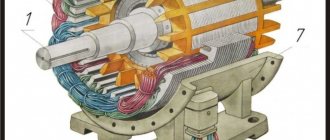
Rotary Power Converters
Electrical machines that convert electrical energy into mechanical work are called electric motors.
Electrical machines that convert mechanical work into electrical energy are called electrical generators.
Mechanical energy usually appears in the form of rotational motion. Electric motors and generators are called rotary power converters or rotating electric machines. The process of converting electrical energy into mechanical work is called electromechanical.
Electrical machines consist of current circuits made of insulated conductors and magnetic cores made of ferromagnetic materials. Machines produce mechanical work through the action of electromagnetic forces on conductors and ferromagnets connected by a magnetic field. Conductors and ferromagnetic elements belong either to the moving part of the machine (rotor) or to the stationary part (stator). The rotation of the moving part of the machine contributes to the change in the magnetic field. In turn, an electromotive force is induced in the conductors, which produces electrical energy. Likewise, electric current in the machine's conductors, called windings, interacts with the magnetic field and creates forces that cause the rotor to move.