POWER DELIVERED IN THE EXTERNAL CIRCUIT
. (2)
From formula (2) it is clear that with a short circuit (R®0) and with R® this power is zero. For all other finite values of R, the power P1> 0. Consequently, the function P1 has a maximum. The value of R0 corresponding to the maximum power can be obtained by differentiating P1 with respect to R and equating the first derivative to zero:
. (3)
From formula (3), taking into account the fact that R and r are always positive, and E? 0, after simple algebraic transformations we get:
R0 = r. (4)
Consequently, the power released in the external circuit reaches its greatest value when the resistance of the external circuit is equal to the internal resistance of the current source.
In this case, the current strength in the circuit (5)
equal to half the short circuit current. In this case, the power released in the external circuit reaches its maximum value equal to
. (6)
When the source is closed to an external resistance, then current flows inside the source and at the same time a certain amount of heat is released at the internal resistance of the source. The power expended to release this heat is equal to
. (7)
Consequently, the total power released in the entire circuit is determined by the formula
= I2(R+r) = IE (8)
What is a current source
A current source is a device that continuously supplies a circuit with electricity. It can be a source of direct current and alternating current. Batteries are sources of direct current, and electrical outlets are sources of alternating current.
One of the most interesting characteristics of power sources is that they are capable of converting non-electrical energy into electrical energy, for example:
- chemical in batteries;
- mechanical in generators;
- solar, etc.
Electrical sources are divided into:
- Independent;
- Dependent (controlled), the output of which depends on the voltage or current elsewhere in the circuit, which can be either constant or varying with time. Used as equivalent power supplies for electronic devices.
When talking about circuit laws and analysis, electrical power supplies are often considered ideal, that is, theoretically capable of providing an infinite amount of energy without loss, while having characteristics represented by a straight line. However, in real or practical sources there is always internal resistance that affects their output.
Important! SPs can be connected in parallel only if they have the same voltage value. The series connection will affect the output voltage.
Types of IP connections
The internal resistance of the power supply is represented as being connected in series with the circuit.
EFFICIENCY
The EFFICIENCY OF the current source is equal to . (9)
From formula (8) it follows that
, (10)
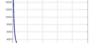
those. P1 changes with the change in current in the circuit according to a parabolic law and takes zero values at I = 0 and at . The first value corresponds to an open circuit (R>> r), the second – to a short circuit (R<< r). Dependence of efficiency on the current strength in the circuit, taking into account formulas (8), (9), (10) will take the form
(11)
Thus, the efficiency reaches its highest value h =1 in the case of an open circuit (I = 0), and then decreases according to a linear law, becoming zero in the case of a short circuit.
Dependence of powers P1, Ptotal = EI and efficiency. current source and the current strength in the circuit are shown in Fig. 1.
Fig.1. I0 E/r
From the graphs it is clear that to obtain both useful power and efficiency. impossible. When the power released in the external section of the circuit P1 reaches its greatest value, efficiency. at this moment it is 50%.
Electrical circuit efficiency
The efficiency factor under consideration is primarily associated with physical quantities characterizing the speed of conversion or transmission of electricity. Among them, power, measured in watts, comes first. There are several formulas to determine it: P = U x I = U2/R = I2 x R.
Electrical circuits may have different voltages and charge amounts, and accordingly, the work performed is also different in each case. Very often there is a need to estimate the speed at which electricity is transmitted or converted. This speed represents the electrical power corresponding to the work done in a certain unit of time. In the form of a formula, this parameter will look like this: P=A/∆t. Therefore, work is displayed as the product of power and time: A=P∙∆t. The unit of work used is the joule (J).
In order to determine how efficient a device, machine, electrical circuit or other similar system is in relation to power and operation, efficiency is used. This value is defined as the ratio of usefully expended energy to the total amount of energy entering the system. Efficiency is denoted by the symbol η, and is defined mathematically as the formula: η = A/Q x 100% = [J]/[J] x 100% = [%], in which A is the work performed by the consumer, Q is the energy given by the source . In accordance with the law of conservation of energy, the efficiency value is always equal to or below unity. This means that useful work cannot exceed the amount of energy expended in doing it.
METHOD AND PROCEDURE OF MEASUREMENTS
Rice. 2.
Assemble the circuit shown in Fig. on the screen. 2. To do this, first click the left mouse button above the emf button. at the bottom of the screen. Move the mouse marker to the working part of the screen where the dots are located. Click the left mouse button in the working part of the screen where the emf source will be located.
Next, place a resistor in series with the source, representing its internal resistance (by first pressing the button at the bottom of the screen) and an ammeter (the button is in the same place). Then arrange the load resistors and voltmeter in the same way, measuring the voltage across the load.
Connect the connecting wires. To do this, click the wire button at the bottom of the screen, and then move the mouse marker to the working area of the circuit. Click with the left mouse button in the areas of the working area of the screen where the connecting wires should be located.
4. Set parameter values for each element. To do this, left-click on the arrow button. Then click on this element. Move the mouse marker to the slider of the regulator that appears, click on the left mouse button and, holding it down, change the parameter value and set the numerical value indicated in Table 1 for your option.
Table 1. Initial parameters of the electrical circuit
| Number option | 1 | 2 | 3 | 4 | 5 | 6 | 7 | 8 |
| E, B | 10,0 | 9,5 | 9,0 | 8,5 | 8,0 | 8,5 | 9,0 | 9,5 |
| r, Ohm | 4,8 | 5,7 | 6,6 | 7,5 | 6,4 | 7,3 | 8,2 | 9,1 |
5. Set the external circuit resistance to 2 Ohms, press the “Count” button and write down the readings of electrical measuring instruments in the corresponding lines of Table 2.
6. Use the regulator slider to consistently increase the resistance of the external circuit by 0.5 Ohms from 2 Ohms to 20 Ohms and, pressing the “Count” button, record the readings of electrical measuring instruments in Table 2.
7. Calculate using formulas (2), (7), (8), (9) P1, P2, Ptot and h for each pair of voltmeter and ammeter readings and write the calculated values in Table 2.
8. Construct on one sheet of graph paper the dependence graphs P1 = f(R), P2 = f(R), Ptot=f(R), h = f (R) and U = f(R).
9. Calculate the measurement errors and draw conclusions based on the results of the experiments.
Table 2. Results of measurements and calculations
| R, Ohm | 2,0 | 2,5 | 3,0 | 20 | |
| U, V | |||||
| I, A | |||||
| P1, W | |||||
| P2, VT | |||||
| Pfull, VT | |||||
| h |
Laboratory work No. 14. “Determination of the efficiency of a direct current source”
Laboratory work No. 14.
"Determination of the efficiency of a direct current source."
Goal of the work
: explore the energy characteristics of a direct current source.
Job Objectives
:
· experimentally check the dependence of the efficiency, total and useful power of a direct current source on the current in the external circuit;
· determine the internal resistance of the source and EMF based on energy characteristics.
Equipment
: DC source, ammeter, voltmeter, rheostat, connecting wires, key.
Theory and method of doing work
:
A current source is a converter of any type of energy into electrical energy. The main characteristics of the current source are electromotive force e
and internal resistance
r
. These characteristics are independent and determine the type of energy characteristics of the source. The source emf can be measured using a voltmeter with a high input resistance. The internal resistance of the source can only be determined by indirect measurements. The electrical energy generated by the current source is transferred to an external circuit - the transmission line and the load (see Fig. 1).
rice. 1
The transmission line connects the current source to the load. The main requirement for the line is minimal losses during energy transmission. The load, as a rule, converts the received electrical energy into energy of another type - mechanical, thermal, light, etc. Each of the elements of the “current source - transmission line - load” system influences the process of energy transmission and conversion. This process is quantitatively described by energy characteristics:
· the power of the current source is the total power developed by the source in the entire circuit, where e
and
I
– emf and source current;
· the useful power of the current source shows what part of the total power can be allocated in the external circuit, where U
– source voltage,
I
– source current,
R
– external circuit resistance;
· efficiency of the current source.
Some of the useful power is irreversibly lost in the transmission line, released in the form of heat. To reduce these losses, they try to make the line resistance as small as possible.
Consider a circuit consisting of a current source with electromotive force e
and internal resistance
r
loaded onto active resistance
R
(see Fig. 1).
In this case, we will assume that the resistance of the transmission line is negligible ( Rl≈0
) and energy losses in it can be neglected. The current in the circuit is determined by Ohm's law for a closed circuit. Taking into account Ohm's law for a complete circuit, the source power can be expressed in terms of source parameters and load resistance. Net power delivered to the load. Hence the source efficiency.
From the above expressions it is clear that the internal resistance has a greater effect on the energy characteristics, the closer the value of r
load resistance
R. This is well illustrated by the graphs in Fig. 2.
rice. 2
From the graphs it is clear that the useful power Pп
, given to the external circuit, is less than the total power of the source
P
over the entire range of load resistances.
Part of the total power is irretrievably lost through the internal resistance of the current source. The dependence Pп(R)
has a pronounced maximum.
It corresponds to the mode in which maximum power is released into the load. The power matching mode is possible if the condition R = r
.
In this mode η=0.5
. Thus, the condition for transmitting maximum power and the condition for achieving maximum efficiency are incompatible.
The voltage matching mode or no-load mode is characterized by the fact that they strive to obtain the maximum voltage at the load. This mode is implemented under the condition R >> r
. In this case, the voltage across the load is close to the source EMF, weakly depends on the load resistance, and the source efficiency is close to unity. The total and useful power of the source is close to zero.
Current matching mode or short circuit mode allows you to obtain maximum current from the source. The mode is implemented under the condition R << r
. In this case, the source current weakly depends on the load resistance. All developed power is released inside the source in the form of heat, which can lead to its failure. Therefore, short circuit mode in most cases is emergency and should be avoided.
In practice, it is more convenient to take energy characteristics in the form of dependences on the source current, since in this case the dependences P(I)
and
η(I)
are linear functions of the current.
To obtain analytical dependences on current for useful power and efficiency, we write for the circuit in Fig. 1 equation, according to Kirchhoff's second rule or Ohm's law for a complete circuit. By multiplying both sides of the equation by current I
, we obtain the power balance equation of the electrical circuit.
Power balance is a consequence of the law of conservation of energy: the total power generated by electrical energy sources is equal to the total power consumed in the entire circuit. From the last equation we express the useful power of the source. Consequently, the graphical dependence P P = f ( I )
is a parabola, the branches of which are directed downwards (see Fig. 3).
rice. 3
Analysis of graphical dependence (see Fig. 4):
rice. 4
1) for point B
:
P P =0
, then, i.e., the abscissa t.
B
corresponds to the short circuit current;
2) since the parabola is symmetrical, then the abscissa is t. A
is half the short circuit current, and the ordinate corresponds to the maximum power value;
3) because in point A
and , then after transformations we obtain
R = r
– the condition under which the power released in the external circuit with a direct current source takes on the maximum value;
4) maximum power value.
The expression for the efficiency of a direct current source takes the form . Therefore, the graphical dependence h = f ( I )
is a straight line located at an angle to the current axis. Graphs of efficiency, total and useful power versus current for a source with a given EMF and internal resistance are shown in Fig. 5.
rice. 5
P(R) curves
,
Pп(R)
and
η(R)
in Figure 2 are defined in the range of changes in
R
from
0
to
∞
.
The functions P(I)
,
Pп(I)
and
η(I)
in Figure 5 are limited along the abscissa axis by the short circuit current
Ik.
z .
Progress
:
1. Assemble the experimental setup according to the diagram shown in Figure 6:
rice. 6
2. Carry out a series of 5-10 experiments, while smoothly moving the rheostat slider, recording the measurement results in the table:
| Current strength | I | A |
| Voltage | U | IN |
3. Construct a graphical relationship in Microsoft Excel using the Chart Wizard, adding a linear trend line, intersecting at the origin, and specifying the equation of the line. Using the main parameters of the equation, determine the possible value of the EMF of the direct current source and the internal resistance.
4. Using the experimental data in the table of paragraph 3, fill out the table for a graphical study of the energy characteristics of a direct current source (power of the current source, useful power of the current source, efficiency):
| Current strength | I | A |
| Voltage | U | IN |
| Power current source | P | W |
| Net power current source | P P | W |
| Current source efficiency | h | % |
5. Construct graphical dependences P(I)
,
Pп(I)
and
η(I)
in Microsoft Excel using the Chart Wizard.
When plotting a graphical relationship in Microsoft Excel, use the Chart Wizard to add a polynomial trend line with degree 2
, intersect the curve with
the OY ( P )
at the origin, and indicate the equation on the chart.
6. Compare the obtained graphical dependencies with the theoretical ones and formulate a general conclusion on the laboratory work.
Questions and tasks for self-control
- Write the Joule-Lenz law in integral and differential forms.
- What is short circuit current?
- What is gross power?
- How is efficiency calculated? current source?
- Prove that the greatest useful power is released when the external and internal resistances of the circuit are equal.
- Is it true that the power released in the internal part of the circuit is constant for a given source?
- A voltmeter was connected to the flashlight battery terminals, which showed 3.5 V.
- Then the voltmeter was disconnected and a lamp was connected in its place, on the base of which it was written: P = 30 W, U = 3.5 V. The lamp did not burn.
- Explain the phenomenon.
- When the battery is alternately shorted to resistances R1 and R2, an equal amount of heat is released in them at the same time. Determine the internal resistance of the battery.