What is a current source
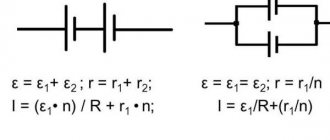
This is a device or element, in the general sense, a two-terminal network in which the current passing through it does not depend on the voltage at the poles. Main characteristics of the current source (IT):
- size;
- internal conductivity (impedance).
The internal resistance of such a two-terminal network is very small. At an ideal source (IIT) it approaches zero.
Graphic designation and current-voltage characteristic (volt-ampere characteristic) IT
Electron motion generators can be either independent or dependent.
The first are an ideal two-terminal network, with two terminals. In them, the current moving from one terminal to another does not depend on the shape and magnitude of the potential difference across the terminals. Its changes occur according to their own laws.
The second type of IT is an ideal two-terminal network, with two terminals, in which the movement of charges from one terminal to another depends on the shape and magnitude of the voltage at these terminals.
There is managed dependent IT. It is an ideal two-terminal network, having 2 input terminals and 2 output terminals. Its peculiarity is that the output current value at the output depends on its value at the input. In such IT there is an increase in power. By changing the zero power value at its input, the amount of power at the output terminals is controlled.
Information. The energy producer can be controlled by voltage (ITUN) or current (ITUT). Some are used for field-effect triodes and vacuum tubes, while others are used for bipolar transistors.
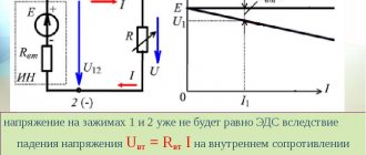
In reality, current generators have certain voltage limitations. They are far from ideal IT and create the movement of electricity in a voltage range where their upper limit depends on Upit IT. Therefore, a real current source has significant load limits.
Power supply parameters
Efficiency of a current source
In practice, you often have to think about what the power of the current source should be, how many watts (W) or kilowatts (kW) are needed to ensure uninterrupted operation of the device. To understand the essence, you need to have an understanding of such concepts used in physics as:
- total circuit energy;
- EMF and voltage;
- internal resistance of the power supply;
- losses within the individual entrepreneur;
- useful power.
Regardless of what kind of energy the source produces (mechanical, electrical, thermal), its power should be selected with a small margin (5-10%).
Total circuit energy
When a load is connected to the circuit, which will consume energy from the current source (IT), the current will do work. The energy released by all consumers and circuit elements included in the circuit (wires, electronic components, etc.) is called total energy. The energy source can be any: generator, battery, thermal boiler. The total energy value will be the sum of the energy spent by the source on losses and the amount spent on performing specific work.
EMF and voltage
What is the difference between these two concepts?
EMF is electromotive force, it is the voltage that external forces (chemical reaction, electromagnetic induction) create inside a current source (IT). EMF is the force of movement of electrical charges in IT.
EMF definition
For your information. It seems possible to measure the value of E (EMF) only in idle mode (idle). Connecting any load causes a loss of voltage inside the power supply.
Voltage (U) is a physical quantity representing the potential difference ϕ1 and ϕ2 at the output of the voltage source (VS).
Potential difference
Net power
The definition of the concept of total power is used not only in relation to electrical circuits. It is also applicable to electric motors, transformers and other devices capable of consuming both active and reactive components of energy.
Losses inside the power supply
Similar losses occur at the internal resistance of a two-terminal network. For a battery, this is the electrolyte resistance; for a generator, this is the winding resistance, the lead wires of which come out of the housing.
Internal power supply resistance
You won’t be able to simply measure R0 with a tester; you definitely need to know it to calculate P0 losses. Therefore, indirect methods are used.
An indirect method for determining R0 is as follows:
- in x.x mode measure E (B);
- when the load Rн (Ohm) is turned on, Uout (V) and current I (A) are measured;
- The voltage drop inside the source is calculated using the formula:
U0=E-Uout.
At the last stage, R0=U0/I is found.
Circuit for measuring R0
Electrical circuit efficiency
By moving charges through a closed circuit, the two-terminal network does some work. When a generator moves charges along the outer circuit of a circuit, this is useful work. When IT moves electrical media throughout the chain, it is said to be fully operational.
Attention! In this chain of charge movement, the efficiency (efficiency factor) of the source is of particular importance. It is equal to the ratio of the external circuit resistance and the total resistance of the circuit.
Paying attention to the efficiency of an electrical circuit, it should be noted that it directly depends on the physical quantities that determine the speed of transmission or transformation of electrical energy. One of these quantities is power P (W).
Power formulas:
P = U * I = U2/R = I2 * R,
Where:
- U – load voltage, V;
- I – current, A;
- R – load resistance, Ohm.
For different circuits, the voltage and current values are different, therefore, the work they produce will be different. When it comes to estimating the speed of transmission and transformation of electric current, pay attention to P. It corresponds to the work done per unit of time:
P = A/∆t,
Where:
- P – power, W;
- A – work, J;
- ∆t – time interval, s.
Based on this formula, to find work A, you need to multiply P by time:
A=P∙∆t
To find the efficiency (η) of an electrical circuit, you need to find the ratio of the useful energy spent to the amount of total energy supplied to the circuit. Formula for calculation:
η = A/Q *100%,
Where:
- A – work done by the consumer, J;
- Q – amount of energy taken from the source, J.
Important! Efficiency cannot be higher than unity. Basically, it is either equal to it or less than it. The reason for this is the Law of Conservation of Energy. According to him, useful work done will never exceed the energy required to perform it.
Efficiency of the current source.
Let's examine the physical characteristics of a closed electrical circuit, including an external resistance, called a payload, and a current source with an electromotive force and internal resistance (Fig. 3). When current passes, heat is generated at both the external and internal resistance. The total thermal power released in the DC circuit is the sum of the useful power
, (6.17)
released in the external circuit, and the heat loss power released inside the current source, i.e.
. (6.18)
Rice. 6.3
Total power develops due to external forces that separate charges in the current source. Using Ohm's law for a closed circuit [see formula (6.13)], expressions for useful and total thermal power can be written in the form
(6.19)
And
. (6.20)
The coefficient of performance (efficiency) of an electrical circuit is defined as the ratio of useful power to total power:
. (6.21)
Thus, efficiency depends on the ratio of internal resistance and load resistance.
What should the load resistance be in order to obtain maximum useful power and maximum efficiency? We will obtain the answer to this question by examining expressions (6.19) and (6.21) graphically and analytically.
The total power is determined by formula (12). Its value is maximum at , i.e. when the source is short-circuited. As can be seen from formulas (11) and (13), in this case Рп and are equal to zero (Fig. 6.4.).
When the apparent power and current are equal to half their maximum values, the efficiency is 0.5, and the useful power reaches its maximum value equal to half the full power at this load.
To make sure that if the load resistance and the internal resistance of the current source are equal, the useful power is really maximum, we transform the right side of expression (6.19) as follows:
. (6.22)
Rice. 6.4.
The useful power is maximum when the denominator of expression (6.22) is minimum. Let's take the derivative with respect to R from this denominator and equate it to zero. As a result, we obtain the equation
, (6.23)
from which it follows that the condition for maximum useful power is indeed the equality of external and internal resistances.
The maximum useful power itself is determined as
, (6.24)
that is, the maximum useful power is equal to a quarter of the short circuit power:
. (6.25)
With an unlimited increase in load resistance, both the total power and the useful power tend to zero, and the efficiency tends to unity (Fig. 6.4).
From Fig. 6.4 it is clear that the requirements for obtaining maximum current in the circuit, maximum useful power and maximum efficiency are contradictory. To obtain the largest possible current, the load resistance must be small compared to the internal resistance of the source, but at the same time, the useful power and efficiency are close to zero, since almost all the work performed by the current source goes to the release of heat at the internal resistance r
.
To obtain maximum useful power from a given current source, a matched load , i.e.
load with resistance. Let's examine the physical characteristics of a closed electrical circuit, including an external resistance, called a payload, and a current source with an electromotive force and internal resistance (Fig. 3). When current passes, heat is generated at both the external and internal resistance. The total thermal power released in the DC circuit is the sum of the useful power
, (6.17)
released in the external circuit, and the heat loss power released inside the current source, i.e.
. (6.18)
Rice. 6.3
Total power develops due to external forces that separate charges in the current source. Using Ohm's law for a closed circuit [see formula (6.13)], expressions for useful and total thermal power can be written in the form
(6.19)
And
. (6.20)
The coefficient of performance (efficiency) of an electrical circuit is defined as the ratio of useful power to total power:
. (6.21)
Thus, efficiency depends on the ratio of internal resistance and load resistance.
What should the load resistance be in order to obtain maximum useful power and maximum efficiency? We will obtain the answer to this question by examining expressions (6.19) and (6.21) graphically and analytically.
The total power is determined by formula (12). Its value is maximum at , i.e. when the source is short-circuited. As can be seen from formulas (11) and (13), in this case Рп and are equal to zero (Fig. 6.4.).
When the apparent power and current are equal to half their maximum values, the efficiency is 0.5, and the useful power reaches its maximum value equal to half the full power at this load.
To make sure that if the load resistance and the internal resistance of the current source are equal, the useful power is really maximum, we transform the right side of expression (6.19) as follows:
. (6.22)
Rice. 6.4.
The useful power is maximum when the denominator of expression (6.22) is minimum. Let's take the derivative with respect to R from this denominator and equate it to zero. As a result, we obtain the equation
, (6.23)
from which it follows that the condition for maximum useful power is indeed the equality of external and internal resistances.
The maximum useful power itself is determined as
, (6.24)
that is, the maximum useful power is equal to a quarter of the short circuit power:
. (6.25)
With an unlimited increase in load resistance, both the total power and the useful power tend to zero, and the efficiency tends to unity (Fig. 6.4).
From Fig. 6.4 it is clear that the requirements for obtaining maximum current in the circuit, maximum useful power and maximum efficiency are contradictory. To obtain the largest possible current, the load resistance must be small compared to the internal resistance of the source, but at the same time, the useful power and efficiency are close to zero, since almost all the work performed by the current source goes to the release of heat at the internal resistance r
.
To obtain maximum useful power from a given current source, a matched load , i.e. load with resistance.
What is IT efficiency
When we talk about the efficiency of a current source, we also consider the useful and total work done by the two-terminal network. By moving electrons in the external circuit, it performs useful work; by moving them throughout the entire circuit, including its internal circuit, it produces complete work.
In formula form it looks like this:
- And useful. = q*U = I*U*t = I2*R*t;
- A full = q*ε = I* ε*t = I2*(R+r)*t.
Where:
- q – amount of energy, J;
- U – voltage, V;
- ε – emf, V;
- I – current, A;
- R – load resistance, Ohm;
- r – source impedance, Ohm;
- t is the time during which the work is done, s.
Taking this into account, we can express the power of a two-terminal network:
- R useful. = A useful/t = I*U = I2*R;
- P full = A total/t = I*ε = I2*(R+r).
The formula for the efficiency of current sources is:
η = P useful/P total= U/ε = R/ R+r.
Study of power and efficiency of current generator
Maximum useful Pmax and maximum efficiencymax are incompatible concepts. Maximum source efficiency cannot be achieved at maximum power. This is due to the fact that P, given by a two-terminal network, will reach its maximum value only if the load resistance and the internal impedance of the IT are matched:
R = r.
In this case, the source efficiency will be:
η = R/ R+r = r/ r+r = 1/2, which is only 50%.
To match the two-terminal network and the load, electronic circuits or matching blocks are used in order to achieve maximum power take-off from the source.
IT power and internal resistance
You can assemble a series circuit that includes a galvanic two-terminal network and a load resistance. A two-terminal network, having an internal impedance r and an emf - E, supplies current I to an external load R. The task of the circuit is to supply electricity to an active load that performs useful work. A light bulb or a heater can be used as a load.
A simple scheme for studying the dependence of Puseful. from R
Considering this circuit, you can determine the dependence of useful power on the resistance value. First, find the R-equivalent of the entire chain.
It looks like this:
Req. = R + r.
The movement of electricity in a circuit is found by the formula:
I = E/(R + r).
In this case, P EMF at the output will be Pout. = E*I = E²/(R + r).
Next, you can find P, dissipated when the generator heats up due to internal resistance:
Pr = I² * r = E² * r/(R + r)².
At the next stage, the power taken by the load is determined:
PR = I² * R = E² * R/(R + r)².
The total P at the output of the two-terminal network will be equal to the sum:
Rych. = Pr + PR.
This means that energy losses initially occur when dissipated by the impedance (internal resistance) of a two-terminal network.
Next, to see at what load value the maximum value of useful power Ruseful is achieved, a graph is drawn.
When examining it, it is clear that the highest power value is at the point where R and r are equal. This is the point where the generator and load resistances are matched.
Attention! When R > r, the current generated in the circuit is small to transfer energy to the load at a sufficient speed. At R < r, a significant portion of the energy is converted into heat in the two-terminal network itself.
The most obvious example of matching can be seen in radio engineering when matching the output impedance of a ULF (low frequency amplifier) and audio speakers. At the amplifier output, the resistance ranges from 4 to 8 ohms, while the Rin of the speaker is 8 ohms. The device allows you to connect to its output stage either one 8 Ohm speaker or two 4 Ohm speakers in parallel. In both cases, the ULF will operate in the specified mode, without loss of power.
In the process of developing certain real current sources, they use its representation in the form of an equivalent block. It consists of two components with which work is carried out: this is the ideal source and its impedance.
Losses and efficiency of DC machines
In DC machines, during operation there is a loss of energy, which consists of three components. The first component is the loss in steel Pst due to hysteresis and eddy currents arising in the armature core. When the machine armature rotates, the steel of its core is continuously remagnetized. Its magnetization reversal requires power, called hysteresis losses.
At the same time, when the armature rotates in a magnetic field, eddy currents are induced in its core. Hysteresis and eddy current losses, called steel losses, turn into heat and heat the armature core. Losses in steel depend on the magnetic induction and the frequency of magnetization reversal of the armature core.
Magnetic induction determines the emf of the machine or, in other words, voltage, and the frequency of magnetization reversal depends on the frequency of rotation of the armature. Therefore, when a DC machine operates in generator or motor mode, the losses in steel will be constant, independent of the load, if the voltage at the armature terminals and its rotation frequency are constant.
The second component includes energy losses due to heating of the wires of the excitation and armature windings by currents passing through them, called losses in copper - Robm . Losses in the armature winding and in the brush contacts depend on the current in the armature, i.e. they are variable - they change with load changes.
The third component is mechanical losses Pmech , which are energy losses due to friction in bearings, friction of rotating parts against air and brushes against the commutator. These losses depend on the rotation speed of the machine armature. Therefore, mechanical losses are also constant and do not depend on the load. Machine efficiency as a percentage: = P2/P1 x 100% where P2 is useful power; P1 is the power consumed by the machine.
When the machine operates as a generator, the useful power is P2 = UI , where U is the voltage at the generator terminals; I is the current in the load.
Power consumption P1 = P2 + Pst + Pext + Pmech = UI + Pst + Pstt + Pmech
and efficiency = (UI/(UI + Pst + Pext + Pmech)) x 100%.
When the machine is operating as an engine, power consumption P1 = UI , where U is the supply voltage; I is the current consumed by the motor from the network.
Net power P2 = P1 - Pst - Prev - Pmech = UI - Pst - Prem - Pmech and efficiency = ((UI - Pst - Prem - Pmech)/UI) x 100%.
OR
In DC machines, the following main types of power losses are distinguished:
1. Power losses in the armature circuit resistance: ΔРя = Iа2ря. As you can see, power losses ΔРя depend on the machine load. Therefore they are called variable power losses.
2. Power losses in steel ΔРc, caused mainly by eddy currents and magnetization reversal of the armature magnetic circuit during its rotation. Part of these losses arise from eddy currents in the surface layer of the pole pieces, caused by pulsating magnetic flux as the armature rotates.
3. Mechanical power losses ΔРmech, caused by friction in bearings, brushes on the commutator, rotating parts on the air.
4. Power losses in the circuit of a parallel or independent excitation winding: ΔРв = UвIв = Iв2рв.
Losses ΔРс, ΔРмех, ΔРв change slightly when the machine load changes, as a result of which they are called constant power losses.
Efficiency of DC machines
η = P2/P1,
where P2 is the useful power of the machine (for a generator it is the electrical power given to the receiver, for an engine it is the mechanical power on the shaft); P1 is the power supplied to the machine (for a generator it is the mechanical power supplied to it by the prime mover, for an engine it is the power it consumes from a direct current source; if the generator has independent excitation, then P1 also includes the power required to power the winding circuit excitement).
| Rice. 9.36. Dependence of the efficiency of DC machines on useful power |
Obviously, the power P1 can be expressed as follows: P1 = P2+ΣΔP,
where ΔP is the sum of the power losses listed above.
Taking into account the last expression
η = P2/(P2 + ΣΔP).
When the machine is idling, the useful power P2 is zero and η = 0. The nature of the change in efficiency with increasing useful power depends on the value and nature of the change in power losses. An approximate graph of the dependence η (P2) is shown in Fig. 9.36.
As the useful power increases, the efficiency first increases at a certain value of P2, reaches its highest value, and then decreases. The latter is explained by a significant increase in variable losses, proportional to the square of the current. Machines are usually calculated in such a way that the highest efficiency value is in the region close to the rated power P2nom. The nominal efficiency value of machines with power from 1 to 100 kW lies approximately in the range from 0.74 to 0.92, respectively.