Article updated: 11/19/2020
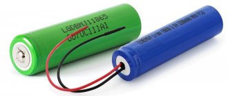
To charge Li-ion batteries 18650 and other sizes, it is important to use reliable and suitable chargers. The charger used must provide a suitable charging current and operate in CC/CV mode, without excessive charging and current overloads.
Buying a ready-made device with the required parameters is easier and more reliable than assembling a charger for 18650 lithium-ion batteries with your own hands. But there is such an opportunity, and every electronics engineer can independently make a charger using a simple circuit.
A little about lithium-ion batteries
These include the following aspects:
- high density of output current and accumulated energy, long-term charge retention;
- no effect of capacity reduction due to regular incomplete charging;
- self-discharge no more than 4-8% per month when stored without recharging, aging no more than 15-20% per year;
- no need for a full discharge to train the energy capacity of the drive;
- light weight, variability of shape and dimensions of the device;
- operating temperature range – from -20°С to +50°С (low temperatures prevent recharging);
- long service life (up to 10 years of operation and more than 1000 discharge cycles).
The disadvantages of lithium batteries are:
- dependence of the service life on the duration of use and storage, and not on the number of discharge cycles;
- risk of failure during overcharging (current flow upon completion of charging);
- low resistance to deep discharge;
- high price;
- explosion hazard due to mechanical damage and excess current, if they lead to heating of the electrolyte and breaking the seal of the housing.
The name of the 18650 battery is due to its shape and dimensions. The battery width is 18 mm and the length is 65 mm. The last number in the marking indicates the cylindrical shape of the battery. The drive circuit is equipped with a controller that prevents overheating during charging.
The battery case can be marked in more detail: for example, INR18650-20R. The first letter distinguishes all lithium-type batteries, the second specifies the type of cathode material (C – cobalt, N – manganese, F – ferrophosphate).
The letter "R" stands for rechargeable. The next 5 digits reflect the dimensions and shape factor of the battery, and the last one is the battery capacity in Ah.
18650 batteries with a protection board can be labeled as 18700 or 18670. The protection board controller helps prevent the battery voltage from exceeding the rated voltage (4.2 V) and falling below 2.5 V.
Charge controller for li-ion battery 18650
Major manufacturers produce standard 18650 lithium batteries without a protective board. This controller, made in the form of an electronic circuit, is installed on top of the case, lengthening it somewhat. The board is located in front of the negative terminal and protects the battery from short circuits, overcharging, and overdischarging. Defense is being assembled in China. There are devices of good quality, but there are outright scams - unreliable information, capacity 9,000A/h. After installing the protection, the case is placed in shrink film with inscriptions. Due to the additional design, the case becomes longer and thicker, and may not fit into the intended slot. Its standard size can be 18700, and can be increased due to additional actions. If the 18650 battery is used to create a 12V battery that has a common charge controller, breakers on the individual Li-ion cells are not needed.
How to charge lithium-ion batteries yourself
The simplest option is to use a mobile phone charger. The devices produce a voltage suitable for restoring the power of 18650 batteries. The method is used only in emergency cases. Its frequent use leads to a decrease in battery capacity.
Homemade charger for a lithium-ion 18650 battery, made from an old phone charger.
To charge the battery, do the following:
- The charger plug is cut off. The wires are stripped of insulation and divided into positive and negative poles. The positive cable most often has a red braid, and the negative cable has a black braid.
- The cleaned wires are attached to the battery poles with plasticine. The USB cable is connected to a computer connector or a special adapter.
- The power source is charged, periodically monitoring the process. It is recommended to charge the battery for no more than an hour. This time is enough to completely restore capacity.
Complex circuits are used to assemble advanced charging. Before starting work, prepare a soldering iron, solder, flux and glue. Separately, purchase the board necessary for the normal functioning of the homemade charger.
https://youtube.com/watch?v=2wMnrZpl3Vo
The assembly is carried out like this:
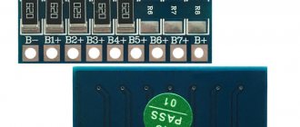
- The board is installed in a plastic box prepared in advance. The structure is supplied with positive and negative wires. The box is used to hold the battery while charging. You can make a container from an old charger, an unusable household appliance or a toy. The dimensions must match the battery parameters.
- The board is soldered, taking into account the markings. The markings make it easy to place the wires. The board is equipped with multi-colored indicators that reflect the charging progress. The microcircuit is glued to the box in a convenient place. After this, observing the polarity, connect the wires. Before fixing, they are cleared of insulation and treated with rosin. A small amount of liquid solder is applied to the board.
During the manufacture of the device, short circuits must not be allowed. The above diagram allows you to assemble a simple but reliable charger in a few hours. Using a USB cable, it is connected to an electrical outlet or computer. The battery is installed in the resulting socket. After the green indicator turns on, the device is turned off.
Assembling a charger for a lithium 18650 battery according to the diagram
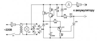
To complete the assembly of electrical components, you need to solder them according to the diagram:
- Connect the positive contact of the power connector to an arbitrary contact of the switch, and the negative contact to the GND terminal of the stabilizer.
- Combine the free contact of the switch with the Vin terminal of the stabilizer.
- On the breadboard, in the range between Vin and GND pins, place 3 capacitors in parallel.
- Place the remaining 1 capacitor between the Vout and GND points.
- Connect the pins Vout and IN+, GND and IN-.
- Connect the positive contact of the battery compartment to terminal B+, and the negative contact to terminal B-.
When using a 5-volt power supply instead of a stabilizer and capacitors, charging the 18650 yourself is even easier. You just need to connect the poles of the power supply to the IN+ and IN- pins of the TP4056 module. After soldering is completed, all that remains is to place the assembled circuit in a plastic case. Using a hot knife, you need to make windows in it along pre-drawn lines to compactly accommodate all components: a USB port, diodes, a switch and a connector.
All components are housed in a homemade housing. The battery compartment is secured with hot melt adhesive. The TP4056 module is installed so that the diodes and USB connector fit into the slots prepared for them, and are glued. At the end, the stabilizer, connector and switch are placed and fixed with glue. Then all that remains is to screw the lid on and sand the edges of the windows with sandpaper. Similarly, you can do it yourself and charge three 18650 batteries using the appropriate circuit.
Previously, our blog provided the main technical characteristics of uninterruptible power supplies.
Which device should you use?
Different models of chargers differ in technical characteristics, set of functions and some other parameters:
Liitokala Lii-500 is a universal charger that automatically selects currents for.
- Simple. Such devices supply a current of 1 A. They have a single socket for installing an 18650 battery.
- Improved. The device is equipped with 2 battery slots. The maximum voltage level is 4.2 V. This charger is more expensive. Additional functions include charge indication. The device automatically limits the procedure time, preventing overcharging.
- Universal. Used to charge power supplies of the 18650 and 26650 types. Models of this type are used to restore the functionality of lithium-ion and nickel-cadmium cells. The best devices are equipped with a safety system that eliminates the need for regular voltage and current measurements.
- Homemade. If a ready-made device cannot be found, the charger can be assembled at home. The components are connected according to the diagrams.
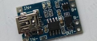
TP4056 Specifications
- Controller used : TP4056 and DW01 to protect the battery from overdischarge and overcharge;
- Charging mode : linear 1%;
- Charging current : up to 1A (configurable);
- Charging Accuracy: 1.5%;
- Input voltage : 4.5 - 5.5V;
- Full charge voltage : 4.2V;
- Indicators : red - charging, green (blue in some versions) - charge complete;
- Input connector : mini USB, MicroUSB or contacts for soldering wires;
- Temperature range : -10 to +85 degrees C;
- Reverse polarity protection : no;
- Overcharge protection : 4.30±0.050 V ;
- Overdischarge protection : 2.40±0.100 V;
- Weight : 5 g;
- Board dimensions : 25 × 17 × 4 mm.
A little about lithium-ion batteries
Features of 18650 battery:
- Long service life. The power supply can withstand up to 600 discharge and charge cycles. Lithium batteries have an extended service life and can retain capacity for a long time.
- Compact sizes. The height of the element is 65 mm, diameter is 18 mm. These numbers formed the basis for the name of the battery. Despite its small size, the battery has ample capabilities.
- Availability of a controller. Most old-style batteries are highly explosive. Chemical reactions take place in the battery case, the speed of which increases many times over when overheated. A mechanical short circuit of several containers containing electrolyte also occurred, leading to a fire. The controller, built into modern power supplies, prevents severe overheating and explosion. It's from overcharging.
- Impossibility of long-term storage. Batteries left unused for a long time quickly lose capacity. Li-ion batteries need to be charged regularly. At the same time, a number of rules are observed to prevent the product from failure. It is necessary to correctly calculate the charge current and limit the voltage. Violation of the rules leads to a decrease in service life.
Opening the Lithium Battery Charger
The autopsy showed that all the parts were in place. This surprised me a little, but after taking a closer look, it turned out that not all of them are what they should be. The first thing that caught my eye was the discrepancy between the capacitance on the label of the electrolytic capacitor and the inscription on the board:
As you can see, the electrolyte capacity should be 10uF (10uF on the board), but in fact it costs 4.7uF. In general, this is not such a critical problem. It would be better, of course, to set the required value, but I didn’t find it. The voltage indicated on the installed capacitor is 50 V. It is unlikely that it is really that high there. But when replacing, it is better to install capacitors at a similar or higher voltage
There is a similar problem with the second electrolyte. 470 uF is indicated, but costs 100. It is installed at the output and is designed for a voltage of 16 volts. Well, I replaced it with the found 330uF/16V. At first there was an idea to install 470 uF, but it didn’t fit.
A capacitor is of course good; the larger the capacitance, the better the smoothing of the output voltage, but it will not change anything fundamentally. Therefore, it was then decided to delve into the topic of what kind of battery charge controller is there.
Which device should you use?
To recharge the 18650 battery, you need to use devices with a rated voltage of 4.2 V. If the lithium-ion drive is planned to be connected to a universal charger, then it must be equipped with a parameter controller and indicators for the end of the process.
The cheapest models have 1-2 slots for batteries, a maximum amperage of up to 1 A and a nominal voltage of 4.2 V. The best charger option for lithium drives is a smart device equipped with a terminal voltage meter, a recovery function after a deep discharge and protection against exceeding the nominal voltage
Restoring li-ion battery 18650
If the battery refuses to work, it may manifest itself as follows:
- The energy source is quickly discharged.
- The battery is dead and won't charge at all.
Any source can quickly discharge if the capacity is lost. This is precisely why overcharge and deep discharge are dangerous, from which protection is provided. But there is no escape from natural aging, when storage in a warehouse annually reduces the capacity of the cans. There are no methods of regeneration, only replacement.
What to do if the battery does not charge after a deep discharge? How to restore li-ion 18650? After the controller disconnects the battery, it still has a reserve of energy capable of delivering 2.8-2.4 V voltage at the poles. But the charger does not recognize a charge up to 3.0V; anything lower is zero. Is it possible to wake up the battery and start the chemical reaction again? What needs to be done to increase the charge of li-ion 18650 to 3.1 -3.3V? You need to use a way to “push” the battery, give it the necessary charge.
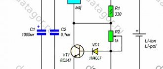
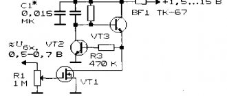
Without going into calculations, use the proposed circuit, mounting it with a 62 Ohm resistor (0.5 W). A 5V power supply is used here.
If the resistor heats up, the lithium battery is zero, which means there is a short circuit or the protection module is faulty.
How to restore a 18650 lithium battery using a universal charger? Set the charge current to 10 mA, and perform precharging as written in the instructions for the device. After raising the voltage to 3.1 V, charge in 2 stages according to the SONY scheme.
How to charge a 18650 battery
Many chargers (chargers) are universal, but when charging lithium-ion batteries you must follow these rules:
0.5-1 A is the optimal charge current for 18650 batteries.
- At the early stage, it is necessary to apply no more than 0.05 V. Finish the procedure by increasing the parameter to 4.2 V. This value is an acceptable safe level for 18650 batteries.
- The charge current should be 0.5-1 A. With a higher value, the charge will be collected faster. However, it is not recommended to immediately supply a current of 1 A. The indicator should increase smoothly.
- Accelerated charging methods should only be used in emergency cases. The procedure time should not exceed 3 hours. Overcharging damages battery components, causing overheating.
- It is recommended to use devices that automatically monitor charging progress. They turn off automatically after the battery reaches the required power. Cheap and homemade devices are not equipped with controllers, so the user will have to independently monitor the progress of the procedure.
Parallel and serial connection of TP4056
TP4056 boards can be conveniently integrated to charge lithium batteries in various home-made devices. But such devices are not always limited to just one 3.7 V battery; sometimes it is necessary to connect entire battery assemblies to a higher voltage. At the same time, I would like to use cheap TP4056 boards for charging. If you look at the characteristics of such a charging board with protection, it clearly says that it is designed to charge a 3.7 V battery, i.e. is a BMS 1S board.
Parallel connection of TP4056 boards
Such boards can be connected in parallel and this will lead to an increase in the charge current, and in the case of connecting boards with protection, to an increase in the controlled discharge current. When connecting the TP4056 in parallel without protection, you need to connect the same pins of the boards together. Such a connection will lead to an increase in the charging current in a multiple of the number of connected boards, i.e. By connecting two boards in this way, we get a charge current of 2 A.
Protection boards are connected in almost the same way. The difference is that they have contacts for connecting batteries and for connecting loads. When connecting TP4056 modules in parallel with protection, the input contacts, contacts for connecting the load, and contacts for connecting the batteries are connected. Such a connection leads not only to an increase in the charge current, but also to an increase in the discharge current, a multiple of the number of installed boards.
Serial connection of TP4056 boards
When assembling lithium batteries at 8.4 V, 12.6 V and higher voltages, many hope to use TP4056 modules with protection to monitor them and charge them at 5 V. By connecting such boards in series with protection, it is actually possible to get more voltage than one battery, and each battery will be protected. With this method, the connectors of the boards for the input voltage are supposed to be connected as in a parallel connection, i.e. combine all positive inputs together and connect all negative inputs together. But as soon as they are connected, the modules will not work properly. Their normal operation is possible provided that the boards are not connected to each other except by output contacts in a serial connection.
It turns out that when TP4056 modules are connected in series, for their normal operation, each such module requires a separate power source to charge a specific battery, i.e. power supplies must be galvanically isolated.
In order to connect all serially connected TP4056 boards to the same power source and charge the batteries, it is necessary to implement some changes to the wiring diagram. You need to install a switch that, at the moment of switching, will change the connection diagram from serial to parallel. Only this method will allow you to charge all the batteries in the assembly from one power source. So for three batteries connected to series-connected TP4056 boards with protection, you will need a toggle switch with six pins, i.e. with two changeover contacts. This can also be implemented using a relay, which will automatically switch to charge mode when supply voltage is applied.
In the initial position, when three batteries are connected in series, the output of the assembly will be 12.6 V with fully charged batteries. After switching the toggle switch, the connection between the terminals of the boards is broken, and the input contacts of the boards are connected in series. Now it will be possible to charge all batteries from one 5 V source. Each battery will be charged independently of the others.
Useful tips for using 18650 batteries
To preserve battery capacity and extend their service life, you need to follow several tips:
- correctly select the operating mode of the charger, and in the absence of a controller, adjust the parameters automatically;
- avoid deep discharge, connect the battery when the charge drops to 70-80%;
- when calculating the recovery duration, take into account not only the number of ampere hours, but also the difference in voltage when charging in a factory and at home, which affects the watt capacity;
- do not try to increase the battery capacity by discharge-charge cycles;
- do not allow the drive to overheat, do not leave it in direct sunlight;
- operate the battery at a temperature of +10…+25°С; for use at low temperatures, insulate the case;
- Avoid impacts on the body of the battery, exposure to strong friction and vibration; during transportation, place batteries on a thick soft substrate;
- store lithium-ion drives with 50-60% charge and at a temperature of about 0°C.
When purchasing a battery, you need to pay attention to the release date. Batteries manufactured more than 3 years ago are considered expired and low-functional.
Charge controller for li-ion battery 18650
Major manufacturers produce standard 18650 lithium batteries without a protective board. This controller, made in the form of an electronic circuit, is installed on top of the case, lengthening it somewhat. The board is located in front of the negative terminal and protects the battery from short circuits, overcharging, and overdischarging. Defense is being assembled in China. There are devices of good quality, but there are outright scams - unreliable information, capacity 9,000A/h. After installing the protection, the case is placed in shrink film with inscriptions. Due to the additional design, the case becomes longer and thicker, and may not fit into the intended slot. Its standard size can be 18700, and can be increased due to additional actions. If the 18650 battery is used to create a 12V battery that has a common charge controller, breakers on the individual Li-ion cells are not needed.
The purpose of protection is to ensure the operation of the energy source within the specified parameters. When charging with a simple charger, the protection will not allow overcharging and will turn off the power in time if the 18650 lithium battery runs down to a voltage of 2.7 V.
How to charge a 18650 battery
When charging a 18650 battery, the following rules must be observed:
- Recovery should begin at a voltage of 0.05 V, gradually increasing it to 4.2 V.
- The range of permissible charge current is 25-50% of the capacity (for example, for a 2000 mAh battery it varies from 0.5 to 1 A).
- The optimal figure is 25-30% of the capacity, the maximum amperage is used only for urgent recharging.
- The permissible charging time when the battery is completely discharged is 3 hours.
- To accurately select the recovery duration, you need to measure its voltage with a multimeter or connect it to an intelligent charger.
The optimal mode consists of two stages:
- CC (constant current). It needs to provide a constant amperage, which is within 20-50% of the battery capacity. With accelerated charging, a higher current value can be used, but it is not recommended to use this mode often. The charger must be equipped with a smooth voltage rise function. At the first stage, the charger works as a current stabilizer.
- CV (constant voltage). When the voltage rises to 4.2 V, you can proceed to the second stage of recharging, at which a voltage of 4.15-4.25 V is maintained. By the end of the first stage, the battery is restored by 70-80%. As the charge accumulates to 90-95%, the amperage will gradually decrease. As soon as its value reaches 1-5% of capacity, the battery can be disconnected from the charger.
Some “charger” models are equipped with a battery recovery mode for deep discharge (less than 2.5 V). The battery is charged with low current (no more than 5-10% of capacity) until its voltage reaches 2.8 V. After this, the charger switches to direct current mode.
Charge controllers and protection circuits - what's the difference?
It is important to understand that the protection module and charge controllers are not the same thing. Yes, their functions overlap to some extent, but calling the protection module built into the battery a charge controller would be a mistake
Now I’ll explain what the difference is.
The most important role of any charge controller is to implement the correct charge profile (typically CC/CV - constant current/constant voltage). That is, the charge controller must be able to limit the charging current at a given level, thereby controlling the amount of energy “poured” into the battery per unit of time. Excess energy is released in the form of heat, so any charge controller gets quite hot during operation.
For this reason, charge controllers are never built into the battery (unlike protection boards). The controllers are simply part of a proper charger and nothing more.
In addition, not a single protection board (or protection module, whatever you want to call it) is capable of limiting the charge current. The board only controls the voltage on the bank itself and, if it goes beyond predetermined limits, opens the output switches, thereby disconnecting the bank from the outside world. By the way, short circuit protection also works on the same principle - during a short circuit, the voltage on the bank drops sharply and the deep discharge protection circuit is triggered.
Confusion between the protection circuits for lithium batteries and charge controllers arose due to the similarity of the response threshold (~4.2V). Only in the case of a protection module, the can is completely disconnected from the external terminals, and in the case of a charge controller, it switches to the voltage stabilization mode and gradually reduces the charging current.
Homemade charger
To charge 18650 batteries yourself, it is important to first study how electrical circuits work, as well as the parameters that allow charging the battery. Several methods are known.
The simplest option is to recharge the battery with a charger suitable for Samsung phones. The current and voltage of this charger are suitable for 18650 batteries.
The connection diagram is quite simple. The charger wires are released from the retaining sheath. The negative contact is determined, as well as the positive wire. The plus is always supplied with a red wire, the minus with a black wire. It's impossible to mix it up.
The bare contacts are connected to the battery, observing the polarity. The wires are fixed with ordinary plasticine. All that remains is to supply power and start charging, regularly monitoring the process. Within an hour, the capacity parameters will be completely restored.
Another method is designed to improve charging. But the connection diagram will be more complicated. To work you will need:
- soldering iron;
- solder;
- glue;
- flux.
The most important element for a home device is the charging board. It is sold in online stores. Assembly is performed in a certain sequence. First, prepare a plastic box with wires (plus, minus). The charging board is soldered to it. The battery is inserted into the box, power is supplied, and charging begins.
To use this option, it is important to select a box (container) whose dimensions correspond to the dimensions of the 18650 battery. The wires must be soldered to places specially marked on the board. To control the amount of charge, the board is equipped with several LED indicators of different shades (red, green).
The board is fixed to the box anywhere, allowing you to see the operation of the indicators. Then the wires are soldered, maintaining the polarity. The ends, before starting soldering, are thoroughly cleaned and then covered with rosin. Liquid flux is dripped onto the surface of the board (2–3 drops).
During soldering, the wires should not contact each other. You can assemble the described circuit yourself very quickly. It is inexpensive, but it is highly reliable and has an excellent charge. After applying voltage, all you have to do is look at the indicator. The green light indicates the battery charge strength.