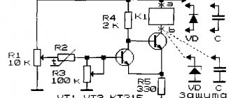
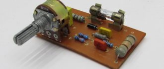
Single-stage AF amplifier
This is the simplest design that allows you to demonstrate the amplification capabilities of a transistor. However, the voltage gain is small - it does not exceed 6, so the scope of such a device is limited.
However, you can connect it to, say, a detector radio (it should be loaded with a 10 kOhm resistor) and use the BF1 headset to listen to broadcasts from a local radio station.
The amplified signal is supplied to input jacks X1, X2, and the supply voltage (as in all other designs of this author, it is 6 V - four galvanic elements with a voltage of 1.5 V each connected in series) is supplied to jacks X3, X4.
Divider R1R2 sets the bias voltage at the base of the transistor, and resistor R3 provides current feedback, which helps temperature stabilization of the amplifier.
Rice. 1. Circuit diagram of a single-stage AF amplifier using a transistor.
How does stabilization occur? Let us assume that, under the influence of temperature, the collector current of the transistor has increased. Accordingly, the voltage drop across resistor R3 will increase. As a result, the emitter current will decrease, and therefore the collector current will decrease - it will reach its original value.
The load of the amplifier stage is a headphone with a resistance of 60.. 100 Ohms. It is not difficult to check the operation of the amplifier; you need to touch the input jack X1, for example, with tweezers you should hear a faint buzzing sound in the phone, as a result of alternating current pickup. The collector current of the transistor is about 3 mA.
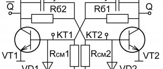
Economical ULF with three transistors
For portable electronic equipment, an important parameter is the efficiency of ULF. The diagram of such a ULF is shown in Fig. 10 [RL 3/00-14]. Here, a cascade connection of field-effect transistor VT1 and bipolar transistor VT3 is used, and transistor VT2 is connected in such a way that it stabilizes the operating point of VT1 and VT3.
As the input voltage increases, this transistor shunts the emitter-base junction of VT3 and reduces the value of the current flowing through transistors VT1 and VT3.
Rice. 10. Circuit of a simple economical low-frequency amplifier with three transistors.
As in the above circuit (see Fig. 6), the input resistance of this ULF can be set in the range from tens of ohms to tens of megohms. A telephone capsule, for example, TK-67 or TM-2V, was used as a load. The telephone capsule, connected using a plug, can simultaneously serve as a power switch for the circuit.
The ULF supply voltage ranges from 1.5 to 15 V, although the functionality of the device is maintained even when the supply voltage is reduced to 0.6 V. In the supply voltage range of 2 ... 15 V, the current consumed by the amplifier is described by the expression:
1(μA) = 52 + 13*(Upit)*(Upit),
where Upit is the supply voltage in Volts (V).
If you turn off transistor VT2, the current consumed by the device increases by an order of magnitude.
Two-stage ultrasonic amplifier using transistors of different structures
It is designed with direct coupling between stages and deep negative DC feedback, which makes its mode independent of ambient temperature. The basis of temperature stabilization is resistor R4, which works similarly to resistor R3 in the previous design
The amplifier is more “sensitive” compared to a single-stage amplifier - the voltage gain reaches 20. An alternating voltage with an amplitude of no more than 30 mV can be supplied to the input jacks, otherwise distortion will occur, which can be heard in the headphone.
They check the amplifier by touching the input jack X1 with tweezers (or just a finger) - a loud sound will be heard in the phone. The amplifier consumes a current of about 8 mA.
Rice. 2. Diagram of a two-stage AF amplifier using transistors of different structures.
This design can be used to amplify weak signals, such as from a microphone. And of course, it will significantly enhance the signal 34 removed from the load of the detector receiver.
Low side current measurement
When measuring current on the low voltage side, a current shunt resistor is placed between the resistive load and ground. The most suitable low-side current measurement circuit is shown in Figure 2. This circuit uses the Texas Instruments INA181 current amplifier , although many other amplifiers can also be used for low-side measurements.
Rice. 2. Low side current sensing circuit using INA181
Measuring current on the low voltage side is easier to implement because the voltage from the current shunt resistor sensor is measured relative to ground. This configuration allows the current amplifier to be used with a low supply voltage because the measured voltage is only a few millivolts above the circuit ground potential. In this configuration, the voltage taken from the sensor is not superimposed on the higher voltage, so common mode rejection is not required. The low voltage side measurement method is the simplest and least expensive method to implement.
The disadvantage of measuring current on the low side is that the load does not have a direct connection to ground due to the shunt resistor, leaving the low side of the load at a voltage of several millivolts relative to ground.
A wiring arrangement without a direct connection to ground may cause problems if there is a short circuit between the load and its frame. Such a short circuit can occur, for example, if a load enclosed in a metal casing, such as a motor, has a winding short circuit to the housing. The current sense resistor may not be able to detect this short circuit.
Additionally, the amplifier's common-mode input voltage must include ground for low-side measurements. This is usually not a problem for amplifiers operating with bipolar power supplies, but it can be a problem with unipolar ones. Therefore, the common-mode voltage range that includes ground becomes an important criterion when selecting a suitable amplifier for low-side measurements.
There is another important aspect of this method of measuring current. Please note that the Texas Instruments ADS114 in Fig. 2 is connected via the power supply directly to ground, and the input circuits of the ADC and INA181 amplifier on the low voltage side are connected to a single ground point.
When measuring current using the small voltages produced across low-impedance shunt resistors by high load current passing through them, it is important to remember that not all ground points may be at the same potential. When large currents from power loads flow through ground circuits or buses, it is quite easy to create a potential difference of several millivolts between two ground points in the system. As a precaution, always keep ground wires very close to each other to minimize voltage differences between them.
To eliminate this source of error when measuring from the low voltage side, the ADC ground reference pin must be connected in close proximity to the bottom side of the current sense resistor and the current amplifier input. Not every convenient part of the ground bus can be selected as a connection point. To be absolutely sure, mark this point and all ground connections to it as a star directly on the diagram.
Likewise, the current amplifier's input offset voltage disproportionately affects gain accuracy when the voltage across the current sense resistor is too low. For this reason, it is best to select an amplifier with a very low input offset voltage. The INA181 amplifier, shown in Figure 2, has an input offset voltage of ±150 µV for the low-side voltage sense circuits, where there is no common-mode voltage.
Despite some disadvantages, low-side current sensing circuitry is a good choice if the load does not require a direct connection to ground and if internal shorts between the load and the frame are either not a problem or should not be detected by the current sensing circuitry.
However, for designs that must meet functional safety requirements, the high-side current measurement method is the best choice.
Two-stage ultrasonic amplifier with transistors of the same structure
Here, a direct connection between the cascades is also used, but the stabilization of the operating mode is somewhat different from previous designs.
Let's assume that the collector current of transistor VT1 has decreased. The voltage drop across this transistor will increase, which will lead to an increase in the voltage across resistor R3 connected in the emitter circuit of transistor VT2.
Due to the connection of the transistors through resistor R2, the base current of the input transistor will increase, which will lead to an increase in its collector current. As a result, the initial change in the collector current of this transistor will be compensated.
Rice. 3. Diagram of a two-stage AF amplifier using transistors of the same structure.
The sensitivity of the amplifier is very high - the gain reaches 100. The gain strongly depends on the capacitance of capacitor C2 - if you turn it off, the gain will decrease. The input voltage should be no more than 2 mV.
The amplifier works well with a detector receiver, an electret microphone and other weak signal sources. The current consumed by the amplifier is about 2 mA.
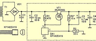
A simple amplifier with one transistor
The simplest ULF, made according to a circuit with a common emitter, is shown in Fig. 1. A telephone capsule is used as a load. The permissible supply voltage for this amplifier is 3…12 V.
It is advisable to determine the value of the bias resistor R1 (tens of kOhms) experimentally, since its optimal value depends on the supply voltage of the amplifier, the resistance of the telephone capsule, and the transmission coefficient of a particular transistor.
Rice. 1. Circuit of a simple ULF on one transistor + capacitor and resistor.
To select the initial value of resistor R1, it should be taken into account that its value should be approximately one hundred or more times greater than the resistance included in the load circuit. To select a bias resistor, it is recommended to connect a constant resistor with a resistance of 20...30 kOhm and a variable resistor with a resistance of 100...1000 kOhm in series, after which, by applying a small amplitude audio signal to the input of the amplifier, for example, from a tape recorder or player, by rotating the variable resistor knob to achieve the best signal quality at its highest volume.
The capacitance value of the transition capacitor C1 (Fig. 1) can range from 1 to 100 μF: the larger the value of this capacitance, the lower frequencies the ULF can amplify. To master the technique of amplifying low frequencies, it is recommended to experiment with the selection of element values and operating modes of amplifiers (Fig. 1 - 4).
Push-pull AF power amplifier using transistors
It is made on transistors of different structures and has a voltage gain of about 10. The highest input voltage can be 0.1 V.
The first two-stage amplifier is assembled on transistor VT1, the second is assembled on VT2 and VT3 of different structures. The first stage amplifies the signal 34 in voltage and both half-waves are equal. The second one amplifies the signal by current, but the cascade on transistor VT2 “works” at positive half-waves, and on transistor VT3 at negative half-waves.
Rice. 4. Push-pull AF power amplifier using transistors.
The direct current mode is chosen such that the voltage at the point of connection of the emitters of the transistors of the second stage is equal to approximately half the voltage of the power source.
This is achieved by turning on the feedback resistor R2. The collector current of the input transistor, flowing through the diode VD1, leads to a voltage drop across it. which is the bias voltage at the bases of the output transistors (relative to their emitters), it allows you to reduce distortion of the amplified signal.
The load (several parallel-connected headphones or a dynamic head) is connected to the amplifier through an oxide capacitor C2.
If the amplifier will operate on a dynamic head (with a resistance of 8 - 10 Ohms), the capacitance of this capacitor should be at least twice as large. Pay attention to the connection of the load of the first stage - resistor R4. Its upper pin in the circuit is not connected to the power supply positive, as is usually done , and with the lower load terminal.
This is the so-called voltage boost circuit, in which a small positive feedback voltage is supplied to the base circuit of the output transistors, equalizing the operating conditions of the transistors.
It was the output impedance that I didn’t like. Essentially, the gain of this amplifier depends on the load resistance, and it is equal to the parallel resistance R4 and the input resistance of the next stage.
I would like the output impedance to be lower. Without hesitation, I installed an emitter follower at the output. At the output I again received almost the same voltage, i.e. 1 volt.
I started checking the output resistance. To my disappointment, when connecting a resistor of about several hundred Ohms to the output, the signal began to be cut off from below. At the same time, there were no distortions at the collector of the first transistor. The input signal began to decrease. In the end, it turned out that the output resistance of this amplifier is only a few tens of ohms, but the output voltage should not exceed 0.1 volts.
Those. At full load, the amplifier amplifies five times and the input voltage at full load should not exceed 20 mV. In this case, we get 0.1 volts of undistorted signal at the output.
That. It turned out that in order to obtain a voltage of the order of a volt at the output, the load of this amplifier must be more than one kilo-ohm. In general, for amplification of ten times for low input voltages, this amplifier is quite suitable if it is easy to not load it.
This can be dealt with by installing a push-pull emitter follower at the output.
It is advisable to select transistors with similar parameters. Resistor R6 needs to be set to half the supply voltage at the emitter connection point. With the details given in the diagram, the output resistance is 30 ohms, and the main thing is that with a load of 270 ohms, the maximum undistorted voltage reaches 2 volts.
There is no step even at low output voltages, because emitter follower operates in class “A”
This emitter follower can be placed at the output of any circuit. In any case, I loaded the headphones with 32 ohms and even 16 ohms. I can hear it normally.
I finished with it and decided to try other schemes. Of course, I didn’t come up with the schemes myself. I was just looking in books.
The second attempt is to strengthen it exactly tenfold.
I took a well-known scheme. I just decided to try it out.
As is known, gain, the input and output impedance of a given amplifier depends on the depth of feedback. It is more convenient to change it by selecting resistors R1 and R2, but leaving their sum constant. This way we will avoid changing the DC mode when the OOS changes.
For convenience, I took a 47 kohm variable as their quality and connected capacitor C1 to the midpoint according to the diagram. Resistor R1, depending on the gain, can be from hundreds of ohms to tens of kilos.
The smaller this resistor, the greater the gain, but the lower the input resistance.
I applied 0.2 volts to the input and used a variable resistor to set the output voltage to ten times higher, i.e. 2 volts.
I moved on to measuring the input and output resistance. The input impedance turned out to be about 200 kohms. Output impedance is about 60 ohms. In this case, the maximum undistorted output voltage is 0.6 volts. With a further increase in the input signal, a lower limit appears. This means that if you do not load it, then the output undistorted voltage can be obtained more than two volts, i.e. Apply about 0.2 volts to the input.
With a 60 ohm load, the output undistorted voltage reaches 0.6 volts with an input voltage of 120 mV
In my opinion it's a good amplifier. I installed it at the input of my voltmeter and got an input sensitivity of 10 mV
More about transistors. I took them whichever came to hand, starting with KT315 and KT31. Those. any low-power transistors, although it makes sense to take transistors with a high current gain. I mean about 100
Strengthen exactly a hundred times.
In principle, nothing prevents you from making the gain of the previous amplifier one hundred times the voltage. To do this, you just need to change the values of resistors R1 and R2.
Because I have a variable resistor there, so I just need to twist it. In this case, R1 decreases and R2 increases. Let's look at the parameters. I supply 10 mV to the input. The input impedance turned out to be about 30 kohms. Output impedance is about 100 ohms. The maximum undistorted output voltage is 1 volt with an input voltage of 10 mV. Those. More than 10 mV cannot be supplied to this amplifier, because signal distortion begins. With a load of 100 ohms, the output produces 0.5 volts of undistorted signal. Based on this, this amplifier can be used.
Several more schemes caught my eye. I decided to check it out too.
Resistor R1 set half the power at the output, i.e. 3 volts in my case.
Further, as above. First, I applied 10 mV to the input and received 0.8 volts at the output. Those. It turned out that it amplifies me 80 times. I didn’t change anything, although resistor R6 could have been slightly increased. Next I checked the output and input resistance and the maximum output voltage at the output at full load of the amplifier. The input impedance turned out to be about 15 kohms. Output impedance is about 150 ohms. Moreover, when the amplifier is loaded with a 150 ohm resistor, the maximum undistorted output voltage of the amplifier is 0.4 volts. With a load of 1 com, you can achieve an undistorted output voltage of 1.5 volts.
If the amplifier is not loaded, the output undistorted voltage at the output is almost half of the supply. If you need a high output voltage on a low-resistance load, then you can install a push-pull emitter follower at the output, as you did in the first circuit.
The third amplifier circuit is a hundred times on two transistors. It is well suited for phantom power, for example from a sound card. If I have time, I’ll try to connect it to the computer, and instead of a microphone, just connect a dynamic head.
The gain depends on the value of resistor R3. I have 5 ohms. The gain turned out to be about 180. Depending on this resistor, the gain can be changed within a wide range. The smaller this resistor, the greater the gain. The disadvantage of this amplifier is that its amplification properties strongly depend on the load resistance and it is better to load it with a resistance greater than R4. This amplifier also has a fairly low input impedance and is only 1.5 kΩ, but if desired, you can install a regular emitter follower on a single transistor at the input. If R4 is set to 1 ohm, then the gain increases to 400, and the input impedance becomes less than one kilo-ohm. The scheme is certainly workable, but its features must be taken into account. And now.
Strengthen it a thousand times or more.
Firstly, you can amplify it a thousand times by placing two amplifiers in series with a coefficient of 100 and 10. To begin with, I will add another stage to the previous amplifier and see what comes of it.
With such amplification, it is advisable to install the first transistor with a normalized noise figure. Using resistor R5, I set half the supply voltage at point “A” so that the limitation with a strong signal would be symmetrical.
The gain with R4 equal to 5 ohms turned out to be 3500.
With R4 equal to 1 ohm, the gain turned out to be more than ten thousand.
The signal from the generator had to be fed through a 1:30 divider
With resistor R4 equal to 5 ohms, the output resistance is about 600 ohms, and the maximum undistorted output voltage reaches 0.7 volts with a voltage at the amplifier input of about 0.4 mV or 400 μV. This is what you like best.
By selecting R4, the gain can be set to 1000 as intended.
With R4 equal to 30 ohms, the gain became 1300. The input impedance was about 10 kohms.
The maximum output voltage when the amplifier was loaded onto a 600 ohm resistor was about 0.7 volts. With a higher load resistance, the output undistorted voltage is even higher. I liked this amplifier.
With R4 equal to 1 ohm, I didn’t look at the parameters. I think it’s unlikely that I’ll ever need a gain of 10,000 times, but who knows.
Hold for ten seconds.
Another task is to obtain a time delay for some time. The best way is to take a microcontroller, write a program and go ahead.
The second way is to use logic.
The third way is to do it with field-effect transistors.
Fourth, is to use the property of CMOS logic that it has a high input resistance and can be used instead of field-effect transistors.
All this is widely known and schemes are easily found using search engines.
In this case, I just decided to try what would happen if I used only bipolar transistors. I didn’t come up with anything new here and these are all essentially elementary schemes.
I just soldered them and saw what I could get from them. Of course, there is nothing to say about the accuracy of shutter speed, it is low, but sometimes this does not matter.
The first scheme is simply “head-on”
I took a composite emitter follower and began charging the capacitance at the input through a resistor.
The power supply for all experiments was 9 volts.
As a result, it turned out that up to the breakdown voltage of the zener diode, the circuit behaves well, but when the first transistor begins to open, the output voltage begins to jump a little, although only slightly. To reduce this, I installed capacitor C2.
For the same reason, the size of the timing transistor does not need to be more than 270 kΩ, but better than about 50 kΩ.
It is also advisable to install a circuit with hysteresis after the emitter follower. In this case, I installed an electromagnetic relay.
The circuit can be started simply by turning on the power or using a button.
If a normally open relay contact is made as shown in the dotted line, then we get a cyclic relay.
The shutter speed with a 270 kΩ resistor and a 1000 μF capacitor turned out to be a little more than 9 minutes.
With a 470 uF capacitor about 6 minutes.
With a 47 uF capacitor, about 25 seconds.
With capacitors of larger capacity, the circuit worked unstable, although it is likely that I simply came across low-quality capacitors.
To obtain hysteresis, instead of an electromechanical relay, I tried to use a Schmidt trigger.
The amount of hysteresis depends on the ratio of resistors R8/R12. I got hysteresis of 1 volt. To connect an actuator to the output, you can connect this circuit.
If a variable timing resistor of the required size is not available, then a current stabilizer circuit can be installed instead. In this case, the value of the variable resistor can be any within the range of 1 – 100 kom. Resistor R1 should have a value approximately ten times smaller than the variable resistor. A circuit with a current stabilizer works even more stable than one with just a variable resistor.
This scheme can be applied to any timer that is discussed here.
The second time relay circuit is essentially a cyclic generator that produces pulses after a given time. Made according to a well-known circuit using a unijunction transistor. It’s just that here is its equivalent made on bipolar transistors.
The circuit is started by turning on the power, although you can place a button in parallel with the timing capacitor.
The shutter speed with resistor R1 equal to 2.5 megohms and with a capacitor of 500 uF is approximately 20 minutes.
Resistor R1 and capacitor C1 can be changed within a wide range.
When tested, it turned out to be 2.5 megohms and 10 microfarads with a shutter speed of 25 seconds.
560 koma and 500 uF, the shutter speed was 4 minutes.
If you put a thyristor at least KU101 at the output, you will get not a cyclic timer, but simply a timer for a given time. As I wrote above, I decided to do it only with bipolar transistors, so I made the thyristor with its transistor equivalent. You just need to remember that the maximum current of such a thyristor is quite small and is determined by the maximum base current of the transistors used. The circuit runs in the same way as above.
If you need an algorithm that when you press a button, let the light come on for 1 minute after 10 minutes, then the timers need to be turned on sequentially and then the first timer will start the second. If the time delay is needed no more than a few seconds, then it can be done simply according to the waiting multivibrator circuit. The pulse duration depends on R3, C1
Given the data on the diagram, the duration is about 15 seconds
Then you can at least do this. We take the first circuit with a Schmidt trigger and connect the last circuit, and to it a transistor circuit for the actuator.
In principle, this can be done with other schemes. You can even connect two identical circuits.
Transmit ten meters.
Another task is when you just want to try to transmit something by radio, at least a few meters to begin with. It’s clear that you need to buy radio modules, supply power to them, connect the antenna and off you go, but that’s for later, but first I just want to see what it is.
Usually the main difficulty is with the receiver. It’s somehow easier with a transmitter, so I decided to take the circuit of the simplest receiver and try it. The receiver circuit is outrageously simple. Of course I didn’t come up with it myself. This is essentially a V.T. super regenerator circuit. Polyakova from Radio 2002 number 3.
The transistor operates in barrier mode. The superization frequency is set by resistor R1 and capacitor C3. My scheme worked immediately. A sign that the circuit is working is the presence of superization pulses at the emitter of the transistor. I got it at 100 kHz.
The frequency at which the receiver operates depends on L1 and C2. I chose the frequency 75 MHz. I’ll write below why. The frequency can be measured with a frequency meter by first unsoldering capacitor C3 from the common wire. In my case, with a carbonyl iron core and without capacitor C2, the receiver covers the broadcast range and later you can try to receive broadcasters. Without a capacitor and with a brass core, the receiver is tuned within the range of 120 - 150 MHz. I'll have to try to take it by air. The frequency can also be controlled using a broadcast receiver by unsoldering capacitor C3
The disadvantage of this receiver is its low load capacity and small value of the useful signal, but this can already be corrected with the help of low-frequency circuits, which is no longer as difficult as HF.
I loaded it onto a circuit with a common collector, which is also a low-pass filter that does not pass the superization frequency to the ULF input. My suppression was not quite complete, but I did not redo the low-pass filter, but simply added a capacitor “C” to the low-pass filter.
Another drawback, but it is inherent in all super-regenerators, is a change in the tuning frequency when you touch the antenna with your hand, so I added UHF at the input. This UHF does not provide any increase in sensitivity, but only allows you to reduce the detuning when touching the antenna. If this is not important, then you don’t have to install it.
This receiver can receive both analogue and digital. First I tried to accept the number.
By the way, in view of the small size of the useful signal, an ULF with a gain of more than a thousand, the circuit of which I had made before, was just useful here.
At the ULF output there is a level clamp on the diode VD1 and capacitor C8. Next comes the threshold element. It can be made using transistors using a Schmitt trigger circuit or using K561TL1. I soldered the Schmitt trigger on two inverters. In my particular case, it is best to set the response voltage to 1.5 volts, because... The amplitude of the pulses at the ULF output was about 3 volts. From the output of the Schmidt trigger, the signal goes to the decoder either at the logic or at the MK. I have logic, but I’m not writing about him here, because... The article describes the use of bipolar transistors as intended, and I’m already “tired” of drawing the circuits. If the decoder is frequency division, then it is clear that no Schmitt trigger is needed, but with ULF the signal is fed to channel filters, which by the way can also be made using transistors. If you have enough patience, I’ll write about them here, but I don’t think I have enough patience.
Now the transmitter is for transmitting numbers. The scheme is standard. Master oscillator based on quartz with a fundamental harmonic of 25 MHz. These are found in network cards. Older cards have 20 MHz crystals. Then the receiver needs to be made at 60 MHz. In it, you can try to increase the capacitor C3 in the circuit, or it is better to wind a coil with a large number of turns. I think you need to make 8 turns with a tap from the third turn.
Quartz is excited at the third harmonic. Next comes the amplifier, which is switched with a digital signal using transistor VT3.
Do not forget to position the coils of the master oscillator and amplifier at an angle of 90 degrees relative to each other.
I didn’t strive for a special range, because... there was no such goal. With antennas on the receiver and transmitter of 10 cm each within the apartment it works fine.
At this point I finished with digital and decided to try with analog.
The circuit for analog reception is almost the same, only the ULF gain was reduced, and a composite emitter follower was installed at the output, which was tested above. It can even handle a small speaker, but I tried it with a 16 ohm earphone.
To begin with, I unsoldered capacitor C3 and tried to receive broadcasters in the range of 100 - 108 MHz
In principle, it is accepted, but the sound quality of wideband FM is of course low with a similar receiver. I screwed in the brass core and tried to receive the air, but we probably don’t have anything here or I didn’t have the patience, so I started making a transmitter for voice transmission.
The transmitter circuit differs from the previous one only in the modulator circuit. A modulator is essentially an amplifier with an emitter follower at the output, and the output stage of the transmitter is powered from it. The voltage at the output of the emitter follower using resistor R4 should be set in this case to slightly less than four volts. You can put a microphone on the input, but I just sent an audio signal from the line output of the computer and listened through the receiver.
I didn't achieve a long range. Essentially these were just experiments, but if the modulator in the transmitter is made with a modulation transformer, the range will be greater. I present the diagram, but without the elements. I did not do this for this receiver. I tried this before with a 27 MHz receiver and it’s been lying on my desk ever since. It also connects the antenna through an extension coil.
It is clear that you can further increase the supply voltage.
Turn off the radio ten meters away.
They also often ask on the forum how to make a simple jammer.
It is an RF generator tunable using varicaps in the FM frequency band. A sawtooth voltage is applied to the varicaps. The circuit was the same as described in timers based on an analogue of a unijunction transistor. To adjust in this range, I found that I needed to feed the saw with an amplitude of one to four volts. The lower limit is set by resistor R4, and the upper limit by resistor R3. I chose 9 volts.
I installed two KD104A diodes in parallel as varicaps.
Resistor R5 sets the current of transistor VT3. The larger it is, the greater the range. I installed 30 ma. You can put two transistors in parallel and increase the current to a level of 50 - 100 mA. Then the range will increase. Perhaps more is possible, only as the current increases, you need to control the temperature of the transistor. I didn’t have the patience to try this, although I had often put transistors in parallel before. With a 40 cm antenna it jams normally throughout the apartment. It is better to make the antenna 1 meter.
The coil is wound on a frame with a diameter of 6 mm. Number of turns 2+5
Winding pitch 1 mm. The diameter of the wire is not critical. I have 0.45 mm
A carbonyl iron core is wrapped into the coil. When setting up, you simply use it to set the frequency swing limits.
If there is no carbonyl core, then you can use a brass (copper, aluminum) one. Just increase the number of turns of the coil. I think you need to wind 3+6 turns.
In principle, a similar circuit can be made on any powerful microwave transistor and I think it will drown out a kilometer, but I didn’t try it. So the writing will not end at all.
I wonder if anyone has read my writing up to this point?
As I wrote at the beginning, I didn’t come up with anything new. I simply took known schemes and checked their performance to make sure that everything worked, and so that such a question would not arise for those who wanted to repeat them.
Two-level voltage indicator
Such a device can be used. for example, to indicate the “depletion” of the battery or to indicate the level of the reproduced signal in a household tape recorder. The indicator layout will demonstrate the principle of its operation.
Rice. 5. Scheme of a two-level voltage indicator.
In the lower position of the variable resistor R1 in the diagram, both transistors are closed, LEDs HL1, HL2 are off. When the resistor slider moves upward, the voltage across it increases. When it reaches the opening voltage of the transistor VT1, the HL1 LED will flash
If you continue to move the engine. the moment will come when transistor VT2 opens after diode VD1. The HL2 LED will also light up. In other words, a low voltage at the indicator input causes only the HL1 LED to glow, and more than both LEDs.
Smoothly reducing the input voltage with a variable resistor, we note that first the HL2 LED goes out, and then HL1. The brightness of the LEDs depends on the limiting resistors R3 and R6; as their resistances increase, the brightness decreases.
To connect the indicator to a real device, you need to disconnect the upper terminal of the variable resistor in the diagram from the positive wire of the power source and apply a controlled voltage to the extreme terminals of this resistor. By moving its slider, you select the indicator's response threshold.
When monitoring only the voltage of the power source, it is permissible to install an AL307G green LED in place of HL2.
Operational amplifier circuits
The circuits for connecting operational amplifiers can be very diverse, so it’s unlikely that I will be able to talk about each one, but I will try to consider the main ones.
Op-amp comparator
The formulas for the comparator circuit will be as follows:
Those. the result will be a voltage corresponding to a logical unit.
Those. the result will be a voltage corresponding to logical zero.
The comparator circuit has a high input resistance (impedance) and a low output.
Let's first consider this circuit for switching on the op-amp in comparator mode. This switching circuit is devoid of feedback. Such circuits are used in digital circuitry when it is necessary to evaluate input signals, find out which is larger and produce the result in digital form. As a result, the output will be logical 1 or logical zero (for example, 5V is 1 and 0V is zero).
Let's say the stabilization voltage of the zener diode is 5V, we applied 3V to input one and 1V to input 2. Next, the following happens in the comparator: the voltage at direct input 1 is used as is (simply because it is a non-inverting input) and the voltage at inverse input 2 is inverted. As a result, where there was 3B remains 3B and where there was 1B there will be -1B.
As a result, 3V-1V = 2V, but thanks to the gain of the op-amp, the output will receive a voltage equal to the voltage of the power source, i.e. about 15V. But the zener diode will work and 5V will go to the output, which corresponds to a logical one.
Now imagine that we threw 3V at input 2 and applied 1V at input 1. The opamp will chew through all this, leave the direct input unchanged, and change the inverse (inverting) input to the opposite of 3V and make -3V.
As a result, 1V-3V = -2V, but according to the operating logic, the minus of the power supply will go to the output, i.e. -15V. But we have a zener diode and it will not miss this and at the output we will have a value close to zero. This will be logical zero for the digital circuit.
Schmitt trigger on op-amp
A little earlier we considered such a circuit for connecting an op-amp as a comparator. A comparator compares two input voltages and produces a result at the output. But in order to compare the input voltage with zero, you need to use the circuit presented just above.
Here the signal is fed to the inverting input and the direct input is grounded to zero.
If we have a voltage greater than zero at the input, then we will have -15V at the output. If the voltage is less than zero, then the output will be +15V.
But what happens if we want to apply a voltage equal to zero? It will never be possible to create such a voltage, because there is no ideal zero and the input signal, even by fractions of a microvolt, will definitely change in one direction or another. As a result, the output will be complete chaos, the output voltage will jump from maximum to minimum many times, which in practice is completely inconvenient.
To get rid of such chaos, a hysteresist is introduced - this is a certain gap within which the output signal will not change.
This gap allows this circuit to be implemented through positive feedback.
Let's imagine that we applied 5V to the input, and at the output at the first moment we get a voltage signal of -15V. Then the positive feedback begins to work out. The feedback is formed by a voltage divider, as a result of which a voltage of -1.36V appears at the direct input of the op-amp.
At the inverse input, the signal is more positive, so the operational amplifier will work as follows. Inside it, the 5V signal is inverted and becomes -5V, then the two signals are added and a negative value is obtained. A negative value due to the gain will become -15V. The output signal will not change until the input signal drops below -1.36V.
Let the input signal change and become -2V. Inside, this -2V is inverted and becomes +2V, and -1.36V will remain as it was. Then all this is added up and a positive value is obtained, which at the output will turn into +15V. At the direct input, the value -1.36V will turn into +1.36V due to feedback. Now, to change the output value to the opposite one, you need to apply a signal of more than 1.36V.
Thus, we have a zone with zero sensitivity with a range from -1.36V to +1.36V. This dead zone is called hysteresis.
Repeater
The simplest owner of negative feedback is a repeater.
The repeater outputs the voltage that was applied to its input. It would seem why this is needed because nothing changes from this. But this makes sense, because let us remember the property of the op-amp: it has a high input impedance and a low output impedance. In circuits, repeaters act as a buffer that protects weak outputs from overload.
To understand how it works, rewind a little back to where we discussed negative feedback. There I mentioned that in the case of negative feedback, the opamp strives in every possible way to achieve equal potential across its inputs. To do this, it adjusts the voltage at its output so that the potential difference at its inputs is zero.
So let’s say we have 1B at the input. In order for potentials at the inputs to be present, the inverting input must also be 1V. That's why he's a repeater.
Non-inverting amplifier
The non-inverting amplifier circuit is very similar to the repeater circuit, only here the feedback is represented by a voltage divider and connected to ground.
Let's see how it all works. Let's say 5V is applied to the input, resistor R1 = 10 Ohm, resistor R2 = 10 Ohm. In order for the voltages at the inputs to be equal, the opamp is forced to raise the voltage at the output so that the potential at the inverse input is equal to the direct one. In this case, the voltage divider divides in half, it turns out that the output voltage should be twice the input voltage.
In general, to apply this switching scheme you don’t even need to rack anything in your head, just use the formula where it’s enough to find out the coefficient K.
Inverting amplifier
And now we will look at the operation of such a switching circuit as an inverting amplifier. For an inverting amplifier there are the following formulas:
An inverting amplifier allows you to amplify a signal while simultaneously inverting (changing the sign) of it. Moreover, we can set any gain. We generate this gain through negative feedback, which is a voltage divider.
Now let's try it in action, let's say we have a 1V signal at the input, resistor R2 = 100 Ohm, resistor R1 = 10 Ohm. The signal from the input goes through R1, then R2 and to the output. Let's say the output signal incredibly becomes 0V. Let's calculate the voltage divider.
1V/110=X/100, hence X = 0.91V
It turns out that at point A the potential is 0.91V, but this contradicts the operational amplifier rule. After all, the opamp strives to equalize the potentials at its inputs. Therefore, the potential at point A will be zero and equal to the potential at point B.
How to make it so that there is 1V at the input and 0V at point A?
To do this, you need to reduce the output voltage. And as a result we get
Unfortunately, the inverting amplifier has one obvious drawback - low input resistance, which is equal to resistor R1.
Three-level voltage indicator
It produces light signals according to the principle less than normal - normal - more than normal. For this purpose, the indicator uses two red LEDs and one green LED.
Rice. 6. Three-level voltage indicator.
At a certain voltage on the motor of the variable resistor R1 (the voltage is normal), both transistors are closed and only the green LED HL3 (works). Moving the resistor slide up in the circuit leads to an increase in voltage (more than normal), and transistor VT1 opens on it.
LED HL3 goes out and HL1 lights up. If the slider is moved down and thus the voltage on it is reduced (“less than normal”), transistor VT1 will close and VT2 will open. The following picture will be observed: first the HL1 LED will go out, then HL3 will light up and soon go out, and finally HL2 will flash.
Due to the low sensitivity of the indicator, a smooth transition is obtained from the extinguishing of one LED to the lighting of another. For example, HL1 has not yet gone out completely, but HL3 is already lighting up.
Integrated or external gain trim resistors?
Figures 2 and 3 show low- and high-side current sensing configurations that use current amplifiers with integrated resistors to adjust the gain. These integrated resistors offer a number of design advantages, including simplified design, reduced board component count, and improved laser-trimmed amplification accuracy. One of the main disadvantages of these amplifiers is that the gain is constant and is set at the factory. This will not be a problem if the gain setting is appropriate for the application. However, in case a specific gain is required because the shunt resistor value was chosen primarily to meet other criteria, it is preferable to select an op-amp in combination with discrete resistors.
In Fig. Figure 4 shows the high-side current sensing amplifier circuit based on Microchip Technology with discrete gain adjustments via tuning resistors.
Rice. 4. High side current measurement using discrete resistors and op amp
In this circuit, the gain of the amplifier is given by the ratio of R2 to R1. Also note that R1* = R1, R2* = R2, and that the value of the current shunt resistor RSEN must be many times smaller than R1 or R2. This is usually not a problem because the current shunt resistor value is typically on the order of milliohms or even sub-milliohms for very high current circuits.
Formulas in Fig. 4 make it clear that using an op-amp and discrete resistors requires greater knowledge of component parameters than using current amplifiers with integrated gain-setting resistors.
Schmitt trigger
As you know, this device is usually used to convert a slowly varying voltage into a rectangular signal. When the variable resistor R1 slider is in the lower position in the circuit, the transistor VT1 is closed.
The voltage at its collector is high, as a result, transistor VT2 is open, which means that LED HL1 is lit. A voltage drop is formed across resistor R3.
Rice. 7. A simple Schmitt trigger on two transistors.
By slowly moving the slider of the variable resistor up the circuit, it will be possible to reach the moment when transistor VT1 opens abruptly and closes VT2. This will happen when the voltage at the base of VT1 exceeds the voltage drop across resistor R3.
The LED will go off. If you then move the slider down, the trigger will return to its original position - the LED will flash. This will happen when the voltage on the slider is less than the LED turn-off voltage.
Cascade ULF circuits using bipolar transistors
In Fig. 8 and 9 show circuits of cascode ULFs using bipolar transistors. Such amplifiers have a fairly high gain Ku. Amplifier in Fig. 8 has Ku=5 in the frequency band from 30 Hz to 120 kHz [MK 2/86-15]. ULF according to the diagram in Fig. 9 with a harmonic coefficient of less than 1% has a gain of 100 [RL 3/99-10].
Rice. 8. Cascade ULF on two transistors with gain = 5.
Rice. 9. Cascade ULF on two transistors with gain = 100.
LM358 connection circuit: voltage-frequency converter
And finally, a circuit that can be used as an analog-to-digital converter. You only need to calculate the period or frequency of the output signals.
- C1 – 0.047 µF;
- DA1 – LM358;
- R1 – 100 kOhm;
- R2 – 50 kOhm;
- R3,R4,R5 – 51 kOhm;
- R6 - 100 kOhm;
- R7 - 10 kOhm.
26 thoughts on “LM358 connection circuit”
This is probably the most common opamp. This is precisely the case when the average characteristics of a part make it in demand in any standard devices. The ability to work well in various modes allows for use in UMZCH, parametric and pulse stabilizers, generators, modulators, regulators, etc. Due to its reliability due to its simplicity, it is used in household, industrial, and even military equipment.
What makes it so popular is its extremely low price; I bought them for 3.5 rubles. I took a hundred, and now I’m putting these “seeds” wherever I can. Except for sound amplification equipment, of course, where mediocre frequency and speed parameters impose serious restrictions on the use of the LM358. Interestingly, this simple op-amp has a fairly high common-mode voltage tolerance, which allows it to be used as a voltage amplifier from a shunt in the “hot” wire of a power supply with an output voltage of up to 27 volts. As in the ninth picture in the publication. It’s just not very good at bias voltage, so you have to choose a larger shunt resistance to compensate for the low accuracy of the operational amplifier. But what can you do? You can’t buy an instrumental amplifier for 3 rubles...
It can also be used in audio amplifiers, but not as a preliminary amplification stage, of course, I fully support this. Receivers are generally one of the few devices in whose amplification stages modern technologies have not reached. I understand that MP3 is all around now, but after a high-quality DAC, microcircuits have nothing left to do. If we are talking about true Hi-Fi (High-Fidelity) stereo sound, of course. In equipment of this level, even the use of vacuum radio tubes is still relevant and in demand.
Can you tell me a couple of radio circuits using vacuum tubes? There are lamps, but I can’t find any diagrams, even on the Internet. I remember when I was a child, I had an Astra reel-to-reel tape recorder, it had three lamps, the sound was loud, but the quality, of course, left much to be desired.
The sound quality was poor - due to the poor quality of the magnetic media and pickups, and not due to the bass enhancement! The amplifier only emphasized these shortcomings. Plus the “sound emitters” made their contribution. Yes, and the amplifier is different, despite the elements used in it. Many old tape recorders, for the above reason, were initially equipped with a low-quality, simplified output stage. What kind of lamps do you have? Their variety is greater than that of transistors, especially bipolar ones. It is difficult to find circuits, but not impossible; it is more difficult for certain lamps, especially if there are two GU-50s.
There are a large number of circuits based on radio tubes in books on radio electronics, for example there is the famous book “Young Radio Amateur” by Borisov, V.G. https://tehosnova.ru/knigi/elektronika/borisov_vg_uniy_radiolubitel_7_izd_p.zip
don’t be kidding, almost all modern sound-reproducing devices fit into the hi-fi standard)
Interestingly, the bases of most dual (stereo)