General classification
The concept itself implies a set of symbols that are intended to identify any structural elements or parts. In accordance with the rules and requirements of GOST 2.701-84, several types are distinguished, differing both in the scope of application and in the type of symbols installed.
The breakdown by type is shown in the table below:
Table: varieties diagram
| № | Scheme type | Letter designation |
| 1 | Electrical | E |
| 2 | Hydraulic | G |
| 3 | Pneumatic | P |
| 4 | Gas (except pneumatic) | X |
| 5 | Kinematic | TO |
| 6 | Vacuum | IN |
| 7 | Optical | L |
| 8 | Energy | R |
| 9 | Divisions | E |
| 10 | Combined | WITH |
Thus, for the same device or object, if necessary, several diagrams can be developed at once, explaining the principle of connection, operation or implementation of functions. For electrical equipment, circuits are divided into several types:
- Fundamental or complete – indicated by the number 3;
- Structural – indicated by the number 1;
- Functional - indicated by the number 2;
- General – indicated by the number 6;
- Installation or connection diagrams - indicated by the number 4;
- Connections – indicated by the number 5;
- Locations and combined are designated by numbers 7 and 0, respectively.
When drawing up a specific diagram, as a rule, alphanumeric designations are used, for example, for an electrical functional marking it will look like E2, for a gas structural one X1, etc.
The principles of graphic designation of any elements on diagrams are determined by industry and state standards. They also establish requirements for the location of components, their sizes, and the application of codes, names or markings.
How does this scheme work?
The symbols of the circuit participants are located in the direction of current (signal) movement - from left to right. The specialist must have prior knowledge of the purpose and operation of the electronic and electrical parts and devices indicated in the diagram.
Groups of interconnected elements are combined into devices that solve different problems:
- power supplies, rectifiers;
- stabilizers and voltage dividers;
- amplifiers of different classes;
- multivibrators, flip-flops, blocking oscillators.
Electrical circuit of the power supply
With experience, a person gains the ability to quickly read an electrical circuit, “see” the currents flowing along the circuits, the distribution of potentials, the shape, duration and amplitude of signals. By taking measurements in the right places in the circuit, the technician can judge the serviceability of the device components.
Definition and purpose of each electrical circuit
Each type of electrical circuit is implemented in the form of a drawing or graphic image, made manually or using printed devices. The main differences are due to the description of certain functions, indication of the sequence, principle of operation, or connection to something.
GOST 2.702-2011 , as well as GOST 2.708-81, are considered quite important .
They install:
- image requirements;
- principles of component arrangement;
- preparation of drawings;
- application of designations and technical characteristics.
Next, we will consider in detail the features of each type of electrical circuit.
Fundamental (full)
A schematic diagram is intended to explain the principle of operation of a particular device. Most often it is used for various distribution devices in power circuits, any devices, etc.
Circuit diagram example
Schematic diagrams must indicate the operating electrical components and the connections between them, power contacts and electrical components connecting radio components. In turn, such electrical circuits are divided into two subtypes: single-line and complete.
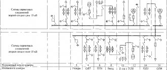
Single-line circuits are also called primary circuits; they usually indicate the power part of the equipment or electrical installation. On the other hand, a single line diagram is widely used to indicate three-phase circuits, where all equipment on three phases has an identical arrangement and connection. Due to this, in the single-line version, only one phase is demonstrated with some deviations in places where the equipment in different phases is different.
In addition to power circuits, there are also low-current circuits for powering protections, measuring equipment and various electronic devices. Such secondary circuit diagrams are called complete, as they show a complete picture of the entire equipment, even highlighting the state of some contacts and parts of the equipment. Alas, due to the complexity of modern equipment, not all devices can be depicted on one sheet, so complete ones can be elemental and expanded.
Full scheme
Structural
Block diagrams provide a general image of a device, all components or individual units of which are made in the form of blocks indicating equipment, and connections between blocks can indicate certain operations connecting individual blocks with each other.
Structural scheme
This type of graphic image is intended to give a general idea of the device and principle of operation, therefore they are often marked with arrows, explanatory inscriptions and other symbols that simplify understanding of the process or explain the operation of the device. To work with such an image, you do not need to have an electrical engineering education, since its designations will be clear even to a person who is not experienced in electricity.
Functional
A functional diagram is a more detailed version of a structural diagram; on it, all elements are also depicted as separate blocks. The main difference is that each block already has an individual form of designation in accordance with its functional purpose. It is also possible to highlight different types of connections between parts, combine parts into blocks, etc.
Functional diagram
General
The general diagram is intended to depict the locations of electrical devices on the ground or within an electrical installation. Determines the main types of electrical connections of these devices, places of their implementation, etc. This type is mandatory when developing various design documents at the design stage. But in addition to the general one, the design documentation includes two more equally important diagrams - connections and connections.
General scheme
Connection diagram (installation)
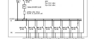
The connection diagram is used to graphically depict electrical equipment connection points. It indicates a specific connection to parts of buildings, distribution systems, in relation to which the installation of electrical equipment should be carried out, due to which this type of diagram is also called installation diagram.
Most often, wiring diagrams are used to indicate the layout of electrical circuits in a building; they are widely used during repairs to indicate places for laying wiring, installing junction boxes and connecting points to devices and device contacts.
Wiring diagram
The figure above shows an example of a wiring diagram; as you can see, each option can have its own symbols, indicated separately. There are links to each specific room and planned electrical equipment, lighting fixtures, etc. In the future, it is used not only for installation work, but can also be used during operation.
Connections
A wiring diagram is used to indicate the principles of connecting various electrical or electronic components into a single system. Sometimes the units are assumed to be geographically separated, in other situations they may be located within the same switchgear, busbar or rack. An example of this is shown in the figure below:
Connection diagram
Depending on the complexity of the graphic and the number of connections displayed, it may be supplemented with connection tables to explain the pinout order and connection of the product.
Locations
It is also part of the design documentation and helps determine the locations of all parts of the electrical installation relative to each other and other significant objects.
Layout diagram
The layout diagram may include:
- components of the entire object, and, if necessary, connections between all parts;
- connecting wires, cables, cords, etc. in a simplified form;
- the name of each element, its type and the document on the basis of which it is applied.
Such an image can be performed in both two-dimensional and three-dimensional space. But in any case, the image must be scaled in relation to actual dimensions and distances.
3D layout
United
Combined scheme
The combined scheme is built on the basis of several types of images that we discussed earlier. This structure is designed to simplify the work of electricians or designers by combining various information into a single whole. But in practice, it is not always advisable to combine several types of graphic elements. This is due to the complexity of some instruments and devices, in which, due to the clutter of elements, it is quite difficult to combine different images.
Types of circuit diagrams
Models of electrical devices, apparatus, equipment, made using digital and alphabetic symbols, as well as graphic images, designed to understand the principles of operation of electrical circuits and the physical processes occurring in them are called schematic diagrams.
Unlike mounting ones, they do not contain data on the location of parts on printed circuit boards. The purpose of this type of drawing is to show the connections of elements with each other, indicate their type and important parameters for reading the diagram. If necessary, graphic materials are supplemented with tables, text footnotes, and diagrams.
Technical documentation of this kind is divided into 2 types:
- Staggered (multilinear) - different circuits are depicted in lines (indicated by Arabic numerals), and in each line all the elements of one circuit are arranged sequentially. This method is suitable for complex electrical and automation devices containing a large number of relays and contact groups in three-phase systems.
- Combined (single-line) - a more visual form of graphical representation of electrical connections between circuit elements. In them, in one drawing, primary circuits with connection diagrams together with control devices for switches, automation, and relay protection can be indicated. Such schemes become less popular as designs become more complex.
Types of electrical circuits.
Application area
When drawing up a schematic diagram of a product, which includes devices that have independent schematic diagrams, each such device is considered as an element of the product schematic, assigned a positional designation, depicted as a rectangle or conventional graphic designation, and written down in the list of elements in one line. The construction of the circuit is carried out using separated and combined methods.
In the case of electrical wiring in a house or apartment, specific locations of lamps, switches, sockets and other elements are indicated.
The diagrams are not drawn to scale; the actual spatial arrangement of the components of the installation products is not taken into account or taken into account approximately. It is allowed, if this does not cause an erroneous connection, to designate the phases with the letters A, B, C.
D - contacts of switching devices:. Designations of elements on a single-line diagram There is also a slight difference between the symbols of the RCD and the differential circuit breaker.
The second one has a neutral position. The designations of these conventional elements can be used in electrical panel diagrams.
The list of elements in Fig. Symbols for detachable plug-plug and detachable terminal block connections, measuring instruments A little simpler with lamps and connections.
Data about the elements must be recorded in the list of elements, see How logical elements work. Part 1
Designations used according to GOST
GOST regulates the following types of designations:
- amendments and inscriptions, rules for the execution of electrical circuits, completeness and types of documents (indicated in the ESKD (Unified System of Design Documentation 2006-2013);
- general requirements for the implementation of schemes, their types and types (GOST 2.701-2008).
The documents define UGO - a conventional graphic designation of individual parts, lines of their interconnection, functional groups and devices. Most imaging is done using software that can be downloaded from the web. You can use online versions of constructors developed taking into account the requirements of the standards. If necessary, it is allowed to use non-standardized UGOs.
Conventional graphic symbols.
On the drawings (near or inside the UGO, in a gap or at the ends of interconnection lines, in free fields) there is text data, the nature of which is determined by the purpose of the circuit diagrams.
Construction Features
The functional diagram includes vertices, with each of which one of the elements A is compared. They also include many states in which the generation of orders is carried out in this particular component. Arcs in this case will mean a transition of control from one element to another. Such a functional diagram, even in the case of complete determinism (certainty) of the subsequent state, may contain branches. This is due to the fact that each point corresponds to a large number of states. The transfer of control will thus depend on the state of the command device or element in which the orders are formulated.
Examples of popular circuit diagrams
As an example, let's look at several options for the most common electrical circuit diagrams.
Electrical circuit diagram of the Ocean 209 radio receiver
The connection between the three pictures placed at the beginning of the publication became clear.
The first one shows the Ocean 209 receiver
On the second - the design of the device
The electrical circuit diagram is supplemented with drawings of printed circuit boards, images of individual radio components and installation instructions
The main disadvantage of this model is the lack of a modern FM range. To listen to your favorite radio stations, you can upgrade.
The drawing shows in red the necessary changes in the electrical circuit diagram
After connecting the antenna, adjust L4 to expand the range to the required parameters. By changing the position of cores L2 and L3 according to the arrow of the standard indicator, the maximum signal amplitude of individual stations is set.
Transistor electrophone Vega 109 stereo: electrical circuit diagram
This technique is designed for listening to recordings created on vinyl records.
Using an electrical circuit diagram, you can make expert repairs or connect old electronics as an audio amplifier to a modern computer
Player Arcturus 006: electrical circuit diagram
This equipment in working condition is capable of providing a high level of quality when playing phonograms from vinyl media.
A careful study of the electrical circuit diagram will allow you to draw the correct conclusion. For full use, this device must be supplemented with an external background corrector and sound amplifier
Ocean 205: electrical circuit diagram
This radio receiver is capable of performing its functions efficiently.
The electrical circuit diagram will be useful for replacing failed parts and setting up
Ocean 214: electrical circuit diagram
Ocean 214 in anniversary version
This circuit diagram shows the parameters that are used for correct configuration.
Almag 01 device: electrical circuit diagram with description of working processes
This technique is used to treat varicose veins, hypertension, and other diseases using magnetic therapy techniques.
The beneficial effect is formed by a series of pulses with a duration of 2-3 ms. Similar equipment is used in professional medical and preventive institutions. This model is suitable for use at home. It does not need to be configured additionally. As standard, there are detailed instructions on how to correctly reproduce workflows.
The electrical circuit diagram will help restore the functionality of the power supply without contacting a technical workshop
Using electrical circuit diagrams helps save time and money. In some situations, even experienced technicians will not restore old equipment with long-term guarantees. After mastering the relevant skills, such problems will be solved independently without extra costs. Comments on a post can be used to answer additional questions.
Video: “How to read electrical circuit diagrams”:
Controversies
When building a functional system, it is important to pay attention to clarifying a number of points. During the image process, some contradictions may emerge, which, however, can be removed with appropriate explanations. In fact, for example, when they say that a dog wags its tail, runs, barks, they mean many different specific states of the animal
However, there is some contradiction here. A state is usually understood as something static. Action is a dynamic phenomenon. It acts more like a change of states. If, for example, in the photo the dog’s tail is in the plane of symmetry, this does not mean that in reality it is frozen in motion. The animal can twirl it, but the picture captures only one moment - a static state. This contradiction can be removed with an appropriate remark. It can be explained that the state includes not only such categories as “position”, but also such as “speed”, “acceleration” and so on. In the considered example with a dog, the description of the condition includes an indication of the tension of the tail muscles, the excitation of the neurons that regulate the position of the muscles
In reality, for example, when they say that a dog wags its tail, runs, barks, they mean many different specific states of the animal. However, there is some contradiction here. A state is usually understood as something static. Action is a dynamic phenomenon. It acts more like a change of states. If, for example, in the photo the dog’s tail is in the plane of symmetry, this does not mean that in reality it is frozen in motion. The animal can twirl it, but the picture captures only one moment - a static state. This contradiction can be removed with an appropriate remark. It can be explained that the state includes not only such categories as “position”, but also such as “speed”, “acceleration” and so on. In the example under consideration with a dog, the description of the state includes an indication of the tension of the tail muscles and the excitation of the neurons that regulate the position of the muscles.
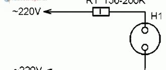
Symbols in electrical diagrams
In technical documentation it is called a housing. Conventional letter and graphic symbols on electrical circuit diagrams When making diagrams, the following graphic symbols are used: 1 conventional graphic symbols established in the standards of the Unified System of Design Documentation, as well as those built on their basis; 2 rectangles; 3 simplified external outlines, including axonometric ones.
Conventional graphic symbols of elements are depicted in the sizes established in the standards for conventional graphic symbols. Since new elements and devices appear every day, new connection methods and it would be impossible to provide designations in advance for all cases. The figures show that each element or device has its own symbol.
Agree, very similar.
At the same time, they monitor the ammeter readings and ensure that the milliammeter shows a current of 0.4 - 0.6 milliampere mA. Depending on their purpose, they are displayed as lighting and warning lamps with corresponding icons.
Electrical circuits. Types. Execution Rules
For example, the electrical circuit diagram is E3, the electrohydropneumokinematic combined circuit diagram is SZ; integrated electrical connection and wiring diagram - EO. Depending on the purpose of the circuit, the drawing shows: a only the supply network circuits, power sources and lines extending from them; b only the distribution network circuits, electrical receivers, lines feeding them; For small objects, the schematic diagram combines images of the supply and distribution network circuits. If, when rotating or mirroring conventional graphic symbols, the meaning or readability of the symbol may be impaired, then such symbols must be depicted in the position in which they are given in the relevant standards.
In nominal mode, all elements operate with the current, voltage and power specified in the device passport. Graphic representations of other elements: Contacts.
Find out the connections between the management structure in question and other levels of management. The places of their connections are nodes, indicated on electrical diagrams in the form of dots. Designations in electrical circuits In the modern period, both domestic and imported elements are used in electrical installation work.
In electrical circuits, the positional designation of an element consists of three parts that have an independent semantic meaning and are written without separating marks and spaces, letters of the Latin alphabet, see. Here's what. The order of the contacts in the table is determined by the convenience of constructing the circuit. It is allowed to conditionally assign designations to the pins on the diagram, and the corresponding indication should be given in the diagram field (Fig.
Excluding elements
Graphs are often depicted in general terms, while omitting unimportant steps and details. In such cases, it may turn out that the state of several different subsystems will determine the path that the command function takes. The condition under which such a transition will occur is usually indicated next to the arc (arrow). In this case, the functional diagram shows that there are two elements in the device. They are blocks for checking and executing operations. In this case, control will move from one subsystem to another according to the arrows. The device may also contain other components. However, the functional diagram does not show them. They are called the environment. These subsystems will never receive control, which is why they are absent from the graph.
Types of electrical circuits
The control circuit diagram is made in a line-by-line manner. So it's easy to distinguish them. The set of diagrams for the installation product should be minimal, but contain information in a volume sufficient for the design, manufacture, operation and repair of the installation product. The designation of contacts can be written down with a qualifying symbol in accordance with GOST 2. Symbols of contactor coils and relays of different types pulse, photo relay, time relay In this case it is easier to remember, since there are quite serious differences in the appearance of additional icons. Some general requirements for the implementation of schemes. Designation of circuits. This designation is used for references in text documents and for application to an object. This type of diagram is detailed, indicating each element, its contacts and connections.
Moreover, the number of pairs of checkmarks or circles indicates the number of wires. Of all types of circuits when designing electrical equipment, the most common are electrical circuits of various types, first of all, electrical circuit diagrams, the basic rules for the execution of drawings of which are set out in these guidelines. The electrical parameters of some elements can be displayed directly in the document, or presented separately in the form of a table.
Some general requirements for the implementation of schemes. They look like a rectangle with small graphic additions. With the spaced method of depicting identical device elements, the contact pin designations are indicated on each component of the device element.
The communication lines running from the midpoint between these elements are made in a single-line representation, indicated by serial numbers 1— To obtain complete information, you must refer to the regulatory documents; the numbers of state standards will be given for each group. B - The same as point A, except that the elements are located on the remote control or electrical panel. On schematic diagrams, in addition to circuits of radio electronics and computer technology, it is allowed to designate electrical circuits in accordance with GOST 2. This type of diagram is detailed, indicating each element, its contacts and connections.
Excerpts from there with the table below. Dimensions in ESKD The dimensions of graphic and letter images in the drawing, the thickness of the lines should not differ, but it is permissible to change them proportionally in the drawing. How to read electrical diagrams.
Block diagram of the software organization of the X.25 network flow control procedure
All second-level programs are executed by the channel processor and are divided into background programs, a background program dispatcher program, and interrupt handling programs.
In Fig. 1 shows a simplified block diagram of the organization of this software.
The following sections provide simplified block diagrams of background programs that perform the function of ensuring the correct sequence of frames. These schemes can be used to develop programs regardless of the programming language.
Background programs, in turn, are divided in the figure into programs that ensure error-free exchange of information frames (Pfo) and programs that perform other functions of the link layer (Pfn). All background programs are managed cyclically and continuously by the Program Manager.
Rice. 1. Block diagram of the organization of software for error-free exchange of information frames at the data link level of the X.25 network
Interrupt programs are allocated to programs for processing one or more bytes for transmission into the channel (to the physical layer) or for reception from the channel (from the physical layer). The interrupt mechanism interrupts the work of the current background program and switches the interrupt program to work. When the interrupt program completes, execution of the interrupted background program resumes.
Background programs that do not perform flow control functions are shown as a single square in the figure. These include functions for establishing and releasing connections, functions for interacting with the network layer of the X.25 network, and other functions.
Program Manager
(
DP
) controls the sequence of all background programs. As can be seen from the figure, all background programs for ensuring the correct sequence of frames are divided into transmitting programs and receiving programs.
The program manager starts a particular background program, and after it is executed, control returns to the program manager so that it starts another background program.
Determining the sequence and frequency of program launches is an independent task of optimizing the software structure in terms of minimizing reception processing delays, frame losses and other quality characteristics. Receive programs often take precedence over transmit programs in a data service. Voice or video service gives priority to background programs
This is explained by the fact that to ensure the quality of data transmission, it is important not to lose a data packet, and for the quality of voice and video transmission, the delay in receiving the packet during transmission is important.
The basic principle of operation of most background programs is the sequential processing of data blocks (frames, packets, etc.) that are queued for servicing by programs. In the case of a point-to-point data link configuration, the following queues are formed:
Op32 – queue of packets for transmission from the network layer to the data link layer; Reupt – queue of “I” (information) frames in case it is necessary to retransmit frames to the channel; OKPM – the queue of all received frames from the channel (i.e., physical layer), in which no errors were detected during the analysis of the PDA (check combination); Op23 is a queue of packets to be transmitted from the data link layer to the network layer.
We present simplified block diagrams of the main background programs for transmission (P1PD, P2PD, P3PD, P4PD, P5PD, P6PD, P7PD), reception (P1PM, P2PM, P3PM, P4PM) with a brief description of their functioning. Let us remind you that background programs are launched by the DP program manager. Upon completion of work, the background program returns control to the DP.
How to learn to read circuit diagrams
In electrical circuits, all components can be divided into several groups: The first group includes devices that generate electricity or power sources. The common wire carries the total current consumed by all elements of the circuit. Find out the connections between the management structure in question and other levels of management. The marking sequence should be determined from the power source to the consumer, and the branching sections of the circuit are marked from top to bottom in the direction from left to right. Interconnection lines should be made with a thickness of 0.2 to 1.0 mm. To determine the optimal operation of the transistor in this case, a milliammeter is connected to the open circuit of the collector circuit. For example, electrical machines may be depicted in a simplified or expanded manner. The sections of the circuit along which the same currents flow are called branches.
At this point, setting the mode of transistor VT1 is considered complete. If you look closely at the diagram, you will notice that next to each conventional image of a radio component there are several Latin letters, for example, VT, BA, C, etc.
Video Each electrical circuit consists of many elements, which, in turn, also include various parts in their design. Depending on this, conditional graphic diagrams are also constructed. Assembly involves certain rules: During assembly, you must be guided in one direction, for example, clockwise.
Fuses are depicted as a rectangle with taps. The communication lines coming from the midpoint between these elements are made in a single-line representation, designated by serial numbers 1— The primary circuits include the circuits through which the main process voltages are supplied directly from sources to consumers or receivers of electricity. Knowing these properties will help you learn to read electrical circuits. Requirements for structural and functional diagrams The structural functional diagram shows all the main functional groups of the product and the connections between them.
In addition, there are and are widely used schematic and wiring diagrams, single-line, full-line and expanded.
Known circuit diagrams
It is better to consolidate reading skills on well-described diagrams, which have already become classic. They contain a small number of integral elements.
Radio receiver “Ishim-003”
The device has been produced since 1984. It is a receiver of frequency and amplitude modulated radio waves in the short, medium and long ranges. Widespread among radio amateurs.
Schematic diagram of Ishim-003.
It is made according to a superheterodyne circuit with two channels (FM and AM) and a frequency converter.
The frequency-modulated channel is made of an RF amplifier, a converter, an amplifier and a frequency detector. An amplitude modulated channel consists of a UHF, an IF, an IF and an amplitude detector.
At low frequencies, amplification is produced by the general ULF. The design includes an electronic counting scale, a setting indicator and a power supply.
Vega-108 stereo
The device appeared in 1979 and is a stereophonic electric record player with an output power of 2*10 W and a sound frequency of 63-18000 Hz. The device not only works as an amplifier for external signals, but can also record to a tape recorder.
The schematic diagram of the electrophone consists of blocks:
- switching;
- regulators;
- nutrition;
- preamp;
- power amplifier module;
- speaker system.
The main part of the elemental base of the player were transistors: KT815V, KT814V, KT315G. The device's power supply includes a step-down transformer with 5 secondary windings, 2 diode bridges and a voltage stabilizer made on a KT315V transistor.
Vega-108 stereo circuit diagram.
The G-602 device is used as a pickup head. The preamplifier consists of 2 channels using transistors KT3102D, KT361E, KT315B. A switch is made of switches and electronic circuitry.
Variable resistors are used as control elements in the regulator. With their help, the values of sound volume, balance, and timbre are set.
Almag-01
The Almag-01 medical device is intended for the treatment of skin diseases, gastrointestinal tract, and ENT organs. It affects the body with a pulsed electromagnetic field.
The device diagram includes:
- power cord;
- inductor coils (emitters);
- cable for connecting the emitter strip to the control unit;
- uninterruptible power supply;
- pulse current generator;
- Control block.
Scheme Almag-01.
The health of the circuit is indicated by a green indicator. Yellow color indicates that pulses are being emitted. A magnetic therapy session lasts 22 minutes, after which the device automatically turns off.
Multimeter DT-832
A universal device for measuring various electrical quantities (voltage, resistance, current, etc.). The basis of the measuring device is the ICL1706 ADC microcontroller or its analogues.
The device includes:
- analog part;
- integrator;
- comparator;
- liquid crystal display;
- digital part with control logic.
The device is convenient to use both at home and at work.