Transformer no-load concept
When a transformer has a dedicated power supply to one winding, while the others are in an open state. This process leads to energy leakage, which is called no-load losses. Its development occurs under the influence of a number of external and internal factors.
The power of the transformer is not fully used, and part of the energy is lost due to some magnetic processes, features of the primary winding and insulating layer. The latter option affects when using devices operating at a higher frequency.
Standardization of energy efficiency of dry-type distribution transformers
To form a model on the basis of which it is possible to standardize energy efficiency (as noted by the author in a number of works [9, 11 12]), it is necessary to consider not one individual or several transformers, but the entire complex of power/distribution transformers that provide power supply over a vast territory, up to territory of a country or group of countries. And fundamental to all subsequent conclusions is the concept of “energy efficiency” .
- On the quantitative side, “ Energy efficiency is characteristics that reflect the ratio of the beneficial effect from the use of energy resources to the expenditure of energy resources incurred in order to obtain such an effect, in relation to products...”. This is the definition of energy efficiency according to 261-FZ.
- On the substantive side, energy efficiency is the controlled state of a large set of devices, organized for some purpose, which characterizes the ability of this set to change (reduce, reduce) the specific costs of operating a given set of devices. This is the author’s conceptual interpretation of energy efficiency, which forms the basis of the developed theory of energy efficiency of power and distribution transformers.
The normalization of short-circuit and short-circuit losses of dry energy-efficient power/distribution transformers is carried out according to the method described in [9].
For adequate comparison with the results of normalizing losses of oil-fired energy-efficient transformers, the following initial data and simplifications for modeling were adopted:
- In test calculations, to simplify the model, it is assumed that all installed transformers are dry. In the methodology outlined in [9], it is also assumed that all transformers are oil-based. You can complicate the model and consider the entire set of transformers, consisting of two groups: 80% oil-based and 20% dry. This will not significantly affect the calculation results.
- As in [9], the target reduction in GDP energy intensity is taken to be 0.08 t.e.f./million rubles.
A complete list of source data is given in Table 4.
| Table 4. Initial data for calculating the standard short-circuit and short-circuit losses of energy-efficient dry power/distribution transformers. | |
| Index | Meaning |
| Total number of distribution transformers in the Russian Federation, pieces, NΣ | 3 020 649 |
| Total transformer power, MVA, SΣ | 846 472 |
| Total losses (at load equal to 1), kW, PΣ | 10 737 243 |
| Target value for reducing GDP energy intensity, t.e./million rubles, ΔE | 0,08 |
| The value of the total share of losses subject to reduction, kW*hour, ΔWΣ | 21 375 000 000 |
| The value of the total power of losses subject to reduction, kW, ΔPΣ | 2 440 000 |
| Specific value of reduced losses, kW/kVA, ΔPud | 0,002882 |
| Share of losses Kхх in the total power losses, | 0,12726 |
| Share of losses Kkz in the total power losses, | 0,87274 |
The values of the obtained energy-efficient losses xx and short-circuit for each rated power of the entire line of dry-type transformers from 25 to 6300 kVA are given in Table 5.
| Table 5. Estimated energy-efficient standard losses for dry-type transformers with a capacity of 25-6300 kVA | |||||||
| Dry transformer power, kVA | Required reduction in specific power of total losses of dry tr-ditch, W | Estimated standard specific power loss xx, E-EF. dry tr-ditch, W | Specific power loss xx of conventional dry tanks, W | Estimated standard specific power of short-circuit losses, E-EFF. dry tr-ditch, W | Specific power of short-circuit losses of conventional dry tr-ditches, W | Energy intensity coefficient (efficiency) e-eff. dry tr-ditch | Energy efficiency coefficient (COP) of conventional dry-type transformers |
| 25 | 0,0721 | 173,2 | 195 | 399,7 | 450 | 0,9763 | 0,9742 |
| 40 | 0,1153 | 201,5 | 230 | 613,2 | 700 | 0,9799 | 0,9768 |
| 63 | 0,1816 | 257,9 | 290 | 1200,5 | 1350 | 0,9801 | 0,9740 |
| 100 | 0,2883 | 334,0 | 380 | 1757,8 | 2000 | 0,9826 | 0,9762 |
| 160 | 0,4612 | 436,7 | 510 | 2312,1 | 2700 | 0,9853 | 0,9799 |
| 250 | 0,7206 | 515,4 | 620 | 3034,0 | 3650 | 0,9880 | 0,9829 |
| 400 | 1,1530 | 916,2 | 1100 | 4830,8 | 5800 | 0,9874 | 0,9828 |
| 630 | 1,8160 | 1100,9 | 1240 | 5583,1 | 7100 | 0,9906 | 0,9868 |
| 1000 | 2,8826 | 1268,6 | 1600 | 6488,8 | 8900 | 0,9925 | 0,9895 |
| 1600 | 4,6121 | 1864,2 | 2100 | 7323,7 | 11000 | 0,9940 | 0,9918 |
| 2500 | 7,2064 | 2476,9 | 2750 | 13416,7 | 19500 | 0,9941 | 0,9911 |
| 4000 | 11,5302 | 2798,9 | 4000 | 24070,9 | 34400 | 0,9941 | 0,9904 |
| 6300 | 18,1601 | 3510,5 | 5400 | 30229,4 | 46500 | 0,9950 | 0,9918 |
To compare with current energy efficiency standards for transformers, Tables 6, 7, 8 show, respectively, the values of the xx and short-circuit losses of energy-efficient transformers in accordance with Government Decree No. 600 of June 17, 2015, STO standard 34.01-3.2-011-2017 and Council of Europe resolution No. 548/2014 dated May 21, 2014
As can be seen from a comparison of the calculation results using the new methodology for normalizing loss indicators of dry energy-efficient transformers, the data obtained, as expected, do not coincide with the loss indicators of regulatory documents. Thus, the obtained values of losses xx and short-circuit for a transformer with a power of 1000 kVA are, respectively, 1270 W and 6500 W; standard values are 1600 and 8900 W. The normative document “Resolution No. 600” requires for this transformer power values of xx losses 1100 W and short-circuit losses 10500 W. The requirements of the European standard are for xx losses 1550 W and for short-circuit losses 9000 W.
If we proceed from the requirements for reducing an intuitive and logically transparent indicator, the scientific criterion of GDP energy intensity, we will see that the requirements for energy efficiency of transformers are manageable and should be justified more flexibly than defined by current regulatory documents.
The author expresses sincere gratitude to the management and leading specialists of Transformer LLC for the numerous technical and other data provided on distribution transformers, as well as for the constructive discussion of the abstracts of the article.
What factors influence losses
Modern transformers reach 99% efficiency under full load conditions. But devices continue to be improved, trying to reduce energy loss, which is almost equal to the sum of idle losses arising under the influence of various factors.
Insulation
If the tie rods have poor or insufficient insulation, a short-circuit will occur. This is one of the main factors for this transformer problem. Therefore, more attention should be paid to the insulation process, using high-quality specialized materials for these purposes.
Eddy currents
The development of eddy currents is associated with the flow of magnetic flux along the magnetic circuit. Their feature is perpendicular to the flow. To reduce them, the magnetic circuit is made of separate elements, pre-insulated. The probability of the occurrence of eddy currents depends on the thickness of the sheet; the smaller it is, the lower the risk of their development, leading to lower power losses.
To reduce eddy currents and increase the electrical resistance of steel, various types of additives are added to the material.
They improve the properties of the material and reduce the risk of developing unfavorable processes that adversely affect the operation of the device.
Hysteresis
Like alternating current, magnetic flux also changes its direction. This indicates alternate magnetization and remagnetization of steel. When the current changes from maximum to zero, the steel demagnetizes and the magnetic induction decreases, but with a certain delay.
When the direction of the current changes, the magnetization curve forms a hysteresis loop. It differs in different grades of steel and depends on what maximum magnetic induction values the material can withstand. The loop covers power, which is gradually overspent on the magnetization process. In this case, the steel is heated, the energy conducted through the transformer is converted into heat and dissipated into the environment, that is, it is wasted, without bringing any benefit to all users.
Characteristics of electrical steel
For transformers, cold-rolled steel is mainly used. But the loss rate in it depends on how well the device was assembled and whether all rules were followed during the production process.
To reduce losses, you can also slightly increase the cross-section of the wires on the winding. But this is not profitable from a financial point of view, because you will have to use more magnetic circuit and other important materials. Therefore, the size of the winding wires is rarely changed. They are trying to find another, more economical way to solve this problem.
Overheat
During operation of the transformer, its elements may heat up. Under these conditions, the device is not able to perform its functions normally. It all depends on the speed of this process. The higher the heating, the faster the device will stop performing its direct functions and will require major repairs and replacement of certain parts.
In the primary winding
If the electric current through the conductor is short-circuited, then there is a high probability of electrical energy leakage. The size of the losses depends on the magnitude of the current in the conductor and its resistance, as well as on the loads placed on the device.
Causes of idle losses
Today, oil and dry transformer devices are used. Until recently, oil transformers were more common, but they have a number of serious disadvantages, for example, low fire safety and difficulty in placement, which is why today dry transformers are used much more often.
Among the main reasons for idle losses in various devices are the following factors:
- Corrosion processes on metal elements of transformers. Corrosion on metal occurs due to damage to the protective varnish layer, which causes eddy currents to increase on the equipment and significant heating of the metal plates.
- Turning short circuits on the windings, which can cause strong voltage surges.
- Low quality insulation.
- Magnetic gaps on metal elements.
- Too many or too few winding turns.
- Overheating of elements of transformer equipment.
These are just the most basic causes of idle losses that experts encounter most often. There are other factors due to which the amount of no-load losses may exceed acceptable limits, which will increase the cost of operating electrical systems. To determine the causes of losses on an individual transformer, the owner will need to order the services of professional electrical measurements.
Below you can use the online calculator to calculate the cost of electrical laboratory services.
Table of losses of power transformers according to reference data depending on the rating
Most often, the problem of electricity leakage is associated with the movement of eddy currents and magnetization reversal. Under the influence of these factors, the magnetic circuit heats up, which causes the bulk of no-load losses, regardless of the load current. The development of this process occurs regardless of the mode in which the device operates.
Gradually, under the influence of certain factors, these indicators may change towards a significant increase.
Loss table XX
| Power kVA | HV/LV voltage, kV | No-load losses W |
| 250 | 10/0,4 | 730 |
| 315 | 10/0,4 | 360 |
| 400 | 10/0,4 | 1000 |
| 500 | 10/0,4 | 1150 |
| 630 | 10/0,4 | 1400 |
| 800 | 10/0,4 | 1800 |
| 1000 | 10/0,4 | 1950 |
Calculation example
To make it easier to understand the presented methodology, you should consider the calculation using a specific example. For example, it is necessary to determine the increase in energy consumption in a 630 kVA power transformer. It is easier to present the source data in the form of a table.
| Designation | Decoding | Meaning |
| NN | Rated voltage, kV | 6 |
| Ea | Active electricity consumed per month, kWh | 37106 |
| NM | Rated power, kVA | 630 |
| PKZ | Transformer short circuit loss, kW | 7,6 |
| XX | No-load losses, kW | 1,31 |
| VERY | Number of hours worked under load, h | 720 |
| cos φ | Power factor | 0,9 |
Based on the data obtained, a calculation can be made. The measurement result will be as follows:
K² = 4.3338
P = 0.38 kW*h
The % loss is 0.001. Their total number is 0.492%.
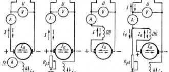
Checking the device in XX mode
To do this, perform the following actions:
- Using a voltmeter, check the voltage supplied to the coil.
- Use another voltmeter to examine the voltage at the remaining terminals. It is important to use a device with sufficient resistance so that the readings are of the required value.
- Connect the ammeter to the primary winding circuit. With its help, you can determine the strength of the no-load current. They also resort to using a wattmeter, with which they try to measure the power level.
After receiving readings from all instruments, calculations are performed that will help in the calculation. To obtain the necessary data, it is necessary to divide the indicators of the first winding by the second. Using the data from the XX experiment with the results of the short-circuit mode, it is determined how fully the device performs its actions.
Features of the XX mode in a three-phase transformer
The operation of a three-phase transformer in this mode is affected by differences in the connection of the windings: the primary coil is in the shape of a triangle and the secondary coil is in the shape of a star. The current helps create its own flow.
Three-phase current in the form of a group of single-phase ones has the following features: the closure of the TGS magnetic flux occurs in each phase due to the core. If the voltage gradually increases, a breakdown will occur in the insulation and the electrical installation will sooner or later fail.
If a transformer uses an armored rod magnetic system, then the development of similar processes can be observed in it.
Conclusion
Energy losses during no-load conditions of the transformer are associated with magnetic losses, losses in the primary winding and insulating layer. Work is still underway to reduce this indicator, despite the fact that the efficiency of modern transformers under high load conditions is 99%.
To reduce the rate of energy leakage, it is necessary to reduce the influence of provoking factors. To achieve this, they are constantly improving the technology for creating devices, using only durable materials, testing them experimentally.
The importance of high quality electrical steel
In order to be able to carry out correct calculations of indicators, data on the characteristic features of various types of steel should be used. In addition, an important factor is such an indicator as the configuration of the magnetic system. All factors can be divided into technological and conditional. The first type of factors include cutting steel into platinum, accuracy when removing burrs, quality of annealing, and varnishing. Factors of the second type include the methods and form of comparison of plates that were made of steel. Also quite an important reason why the number of losses in equipment that is already in use increases is the presence of unstable characteristics of the steel itself. Malfunctions are also possible due to careless assembly, which caused mechanical damage.
Despite the above information, when using equipment that was assembled in full compliance with all standards, there are still deviations from ideal indicators, which amount to approximately five percent. Therefore, this feature must be taken into account when monitoring limit values. Therefore, to the parameters specified in the general GOST standard, you should still add the probability of transformer no-load loss. This figure can be approximately fifteen percent. It is important to control half of this value.