The experience of no-load operation of a transformer, generator, or asynchronous motor is recommended for study by electricians for the reason that the data obtained as a result of such research make it possible to characterize the operation of the device under load. Often this experiment is carried out in conjunction with a short circuit test. Such a program provides data for calculating the efficiency of the device.
Transformer types
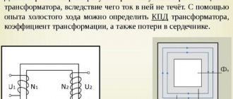
Transformer no-load mode
This mode is characterized by the supply of alternating voltage, changing according to the sinusoid principle, to the primary winding of the device, while in the secondary winding, which is in an open state, there is no electric current at all. In this case, the transformer device resembles an inductor with a closed ferromagnetic magnetic circuit. To conduct experiments with a transformer in this state, you will need to study the circuit diagram corresponding to the device used (single-phase or three-phase).
Transformer diagram at idle
Experiment methodology
The no-load losses of the transformer are determined when creating a certain mode. To do this, the current supply to all windings is stopped. They remain open. After this, the circuits are supplied with electricity. It is determined only on the first circuit. The equipment must operate under the voltage that is set by the manufacturer during its production.
Currents flow through the primary circuit of a power, welding or other installation, which are called XX. Their value is no more than 3-9% of the indicator specified by the manufacturer. In this case, there is no electricity on the secondary circuit winding. In the primary circuit, current produces magnetic flux. It crosses the turns of both windings. In this case, an EMF of self-induction occurs on the primary circuit and mutual induction on the secondary winding.
For example, the open-circuit voltage of a low- and medium-power welding transformer represents the mutual induction emf.
Measurement approach
Measuring no-load losses can be done in two aspects. They are called steel and copper losses. The second indicator indicates heat dissipation in the windings (they begin to heat up). During the experiment this figure is very small. Therefore they are neglected.
About the idle experience
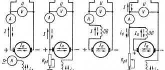
Carrying out an idle test allows you to find out the main indicators of the functioning of the device: the lost percentage of power, the transformation ratio, the value of the electric current during idle operation. The experiment is carried out using measuring instruments: a wattmeter, an ammeter and a pair of voltmeters, one of which (higher in internal resistance) is connected to the terminals of the secondary winding. The primary is supplied with rated voltage.
Transformer calculation
During the experiment you can find:
- no-load electric current (measured with an ammeter) - usually its value is small, no more than 0.1 of the rated current of the first winding;
- power lost in the magnetic circuit of the device;
- voltage transformation indicator - approximately equal to the value in the primary circuit divided by that for the secondary (both values are data from voltmeters);
- Based on the results of measurements of current, power and voltage of the primary electrical circuit, the power factor can be calculated: the power is divided by the product of two other quantities.
The procedure looks like this: the primary coil (or HV) is connected to the power source through three traditional measuring instruments (ampere, watt, and voltmeter). The secondary (LV) leads are short-circuited. The electrical current consumed will be very high, especially considering the low winding resistance. For rated current, voltage and power are measured. The primary coil requires low voltage. It, like the current for XX, has a very low value compared to the nominal value - around 0.05. However, this technical characteristic is of great practical importance - it is used to calculate the secondary voltage and find out whether it is permissible to connect devices in parallel.
Important! Power losses in the core can be ignored due to the negligible voltage. The readings on the wattmeter are therefore taken as copper losses.
The operating resistance of the winding R can be found as follows:
R=P/I2,
Where:
- P – voltmeter data,
- I – current strength.
The general resistance indicator is Z=U/I, the reactive indicator is X = √ (Z² - R²).
Conducting a short circuit experiment
Short circuit voltage characteristic
The parameter under consideration is one of the main characteristics of transformer devices. Its indicators should be minimal to avoid excessive limitations of short-circuit currents. The tests carried out establish their compliance with the standards and requirements determined by the PUE. At the same time, the condition of the wire insulation is checked.
In transformers with two voltage windings, the short circuit is the value, normalized to a given temperature and rated frequency, applied to one of the windings while the other is short-circuited. After this, the rated current is set in each winding, and the switch is positioned to supply the rated voltage.
Using the short-circuit voltage, you can set the voltage drop, external characteristics and short-circuit currents of the converter. These data are taken into account when further connecting the transformer to parallel operation. The short circuit voltage includes active and reactive components.
The value of the active component is determined as a percentage and is calculated by the following formula: Ua = (Pob1 + Pob2)/10Sн = Rob/10Sн, in which Rob is the total loss in the transformer windings, Sn is the rated power of the device (kVA).
The principle of operation of a transformer in idle mode
When a sinusoidal voltage is applied to the winding of the device, a weak current appears in it, usually not exceeding 0.05-0.1 of the rated value (this is the no-load current). It is created by a winding magnetomotive force; it is because of its action that a leading magnetic flux (denoted F) and a scattering flux F1, closed around the winding body, arise in a closed magnetic conductor element. The value of the magnetomotive force is equal to the product of the no-load current and the number of winding turns.
Transformation ratio
The leading flow creates two electromotive forces in the device: self-induction in the first winding and mutual induction in the second. F1 produces a leakage emf at the first coil. It has a very small value, because the flow that creates it is closed, for the most part, through air masses, the leading flow F is through the magnetic circuit. Since the main flow has a much larger scale, the electromotive force it generates for the primary coil is also much larger.
Important! Since the supplied voltage has the form of a sinusoid, the main flow and the winding electromotive forces it creates have the same characteristics. But due to magnetic saturation, the flux present in the device is disproportionate to the electric current that creates magnetization, so the latter will not be sinusoidal. It is practiced to replace its real curve with a corresponding sinusoid with the same value. Current distortion is associated with the third harmonic component (a value determined by eddy flows and magnetic saturation).
What does the magnetic flux of mutual induction in XX mode depend on?
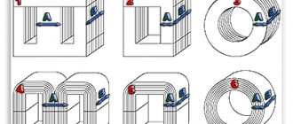
The magnetic flux of mutual induction in a transformer depends on the method of placing the windings on the core and their design.
An important role is played by the fill factor of the magnetic circuit window, which shows the ratio of the total space to the space occupied by the winding.
The closer this coefficient is to unity, the higher the mutual inductance of the windings will be and the lower the losses in the transformer.
Loss table
Features of operation and application of the Tesla resonant transformer
When the second coil circuit is open, it does not use any operating power. The power that the first one consumes has a certain active percentage (this represents the losses of the device), but the reactive one, responsible for magnetization and given to the generator, dominates. As for the lost power, most of it is spent on magnetization reversal processes and the generation of magnetic circuit current eddies. Because of this, the latter begins to overheat. Since the leakage flux does not depend on the load electric current, there are power losses not only at idle, but also when applying loads. Another part of the losses (very small) is spent on heating the coil wire. Its low value is due to the wiring resistance and no-load current.
At a voltage of 10/0.4 kV, the amount of losses will increase as the power increases. For a rated power of 250 kVA, the losses will be 730 W, for 400 kVA - 1000 W, for 2500 kVA - 4200 W. After years of operation, processes occur in the magnetic circuit that increase the amount of losses: the insulation wears out, the structural characteristics of the metal change. Because of this, up to 50% of power can be lost.
Loss measurement
Losses in the magnetic drive are measured exclusively when using a powerful installation. In this case, you can take for calculations a reduced voltage, which is connected to the primary circuit through a wattmeter. This is a direct measurement method.
When taking into account the readings of a voltmeter or ammeter, you will need to multiply their powers by each other. This is an indirect method. However, the result has a certain error. The distortion occurs due to the inability to take into account the power factor in such a calculation. This is the cone angle that is formed in a vector circuit between voltage and current. In idle mode, an angle of 90º appears between them.
Application of a wattmeter
The wattmeter allows you to measure taking into account the power factor. This makes it possible to obtain a more accurate result. The calculation is performed using the following formula:
Next, you need to create a vector diagram based on the obtained result. For each phase, established losses are taken into account. For this purpose, a table is most often built. In this case, the scheme that was originally used by the manufacturer when creating the equipment is used.
The obtained result cannot be compared with the standards. The indicators are compared only with the characteristics of previous inspections. If losses only increase over time, this indicates a violation of the insulation of the magnetic drive plates or the appearance of other violations. It is impossible to reverse this process.
Carrying out idle speed measurements allows you to assess the condition of the equipment, as well as determine the need for scheduled or emergency repairs. Therefore, regular tests allow you to correctly plan the operation of the installation and prevent its unexpected shutdown.
Interesting video: Description of the basics of a transformer.
Checking work
The main purpose of this experiment in combination with the short-circuited state experiment is to find the efficiency of the transforming device. After setting the transformer in the proper mode, the following measurements are carried out:
- Voltage data sent to the first winding, and then to the terminals of the second. You can do this not only with a pair of voltmeters, but also with a multimeter, setting the appropriate operating mode. If voltmeters are used for measurements, a device with a high resistance value is placed on the second coil to maintain zero current. Having measured both indicators, you can find the transformation ratio by dividing the value of the primary coil by that of the secondary.
- A wattmeter is placed in the primary electrical circuit to record power consumption. An ammeter is connected to it; it shows the current strength of the device operating at idle speed.
Measuring transformer voltage with a multimeter
General design and operating principle of the transformer
Structurally, the transformer consists of the following main parts:
- Closed core made of ferromagnetic material.
- Windings
The windings can be wound on a rigid frame or have a frameless design. Specially treated steel is used as the cores of industrial frequency voltage transformers. In some cases, there are devices without a core, but they are used only in the field of high-frequency circuitry and will not be considered within the framework of this topic.
The operating principle of the design in question is as follows:
- When the primary winding is connected to an alternating voltage source, it generates an alternating electromagnetic field.
- Under the influence of this field, a magnetic field is formed in the core.
- The magnetic field of the core, due to electromagnetic induction, creates an induced emf in all windings.
No-load three-phase transformer
The functioning of such a device in the considered mode depends on the design of its magnetic system. If a device similar to a group of single-phase transformers or an armored rod system is used, the third harmonic component for each phase will be closed in a separate core, gaining a value of up to 20% of the active magnetic flux. An additional electromotive force is created that can reach a very high value - 0.5-0.6 of the main EMF. Such processes can cause a violation of the integrity of the insulation, followed by breakdown of the electrical installation. The best option is a system with three rods, then the third component will not go along the magnetic circuit, but will be closed in air or another medium with a low magnetic permeability (for example, oil). In this case, a massive additional EMF, introducing serious distortions, will not develop.
Scheme of no-load experiment of a three-phase two-winding transformer
Transformer parameters based on no-load experiments
The device passport indicates a number of quantities that can help in calculating such operational indicators as the maximum short-circuit current value obtained in practice, energy losses, and the amplitude of receiver voltage variability with a changing current. These quantities are divided into two groups. The first belongs to operation in idle mode: this includes the current strength as a percentage of the nominal and the power losses of the magnetic circuit. The second is winding losses during a short circuit and the voltage (also indicated relative to the nominal) in this state.
Transformer efficiency calculation
Energy losses in the device, occurring in copper and steel components, cause a discrepancy between the output and consumer power parameters. You can find out how efficient a device is by calculating its efficiency: it is equal to the quotient of the output and consumed values. The latter is equal to the sum of the first, losses for the steel core (they are determined during the no-load experiment) and for copper elements (calculated from measurements of the short-circuited device).
Conducting short-circuit and short-circuit tests is a reliable way to calculate the efficiency of a transformer. It also allows you to determine the volume of energy losses and find out which component accounts for most of them.
Video
Coffee capsule Nescafe Dolce Gusto Cappuccino, 3 packs of 16 capsules
1305 ₽ More details
Coffee capsules Nescafe Dolce Gusto Cappuccino, 8 servings (16 capsules)
435 ₽ More details
Apple iPhone 11 Pro 256GB