What is a diode bridge and what elements does it consist of?
A diode bridge in circuits used in networks with single-phase voltage consists of four diodes, which are a semiconductor element with one pn junction. The current in such a semiconductor passes only in one direction when the anode is connected to the plus of the source, and the cathode to the minus. If the connection is reversed, the current is closed. A diode bridge for three-phase electric current is distinguished by the presence of six diodes rather than four. There are no significant differences in the operating principle between bridge circuits for single-phase and three-phase networks.
Diode device
A Schottky diode is another type of semiconductor element used in diode bridges. Its main difference is the metal-semiconductor junction called the "Schottky barrier". Like the pn junction, it provides one-way conduction. For the manufacture of Schottky devices, gallium arsenide, silicon and metals are used: gold, platinum, tungsten, palladium. When applying small voltages - up to 60 V - the Schottky diode is characterized by a low voltage drop across the junction (no more than 0.4 V) and high speed. At a household voltage of 220 V, it behaves like a conventional silicon rectifier semiconductor. Assemblies of such semiconductor devices are often installed in switching power supplies.
History of invention
In 1873, the English scientist Frederick Guthrie developed the operating principle of directly heated vacuum tube diodes. A year later, in Germany, physicist Karl Ferdinand Braun suggested similar properties in solid-state materials and invented a point rectifier.
In early 1904, John Fleming created the first complete tube diode. He used copper oxide as the material for its manufacture. Diodes have begun to be widely used in radio frequency detectors. The study of semiconductors led to the invention of the crystal detector in 1906 by Greenleaf Witter Pickard.
In the mid-30s of the 20th century, the main research of physicists was aimed at studying the phenomena occurring at the metal-semiconductor contact boundary. Their result was the production of a silicon ingot with two types of conductivity. While studying it, in 1939, the American scientist Russell Ohl discovered a phenomenon later called the pn transition. He found that depending on the impurities existing at the interface of two semiconductors, the reducibility changes. In the early 50s, Bell Telephone Labs engineers developed planar diodes, and five years later, germanium-based diodes with a transition of less than 3 cm appeared in the USSR.
The inventor of the rectifier bridge circuit is considered to be an electrical engineer from Poland, Karol Pollak. Later, the results of Leo Graetz’s research were published in the journal Elektronische Zeitung, so in the literature one can also find another name for a diode bridge - circuit or Graetz bridge.
How a diode bridge works: for dummies, simple and short
An alternating current is supplied to the input of the diode bridge, the polarity of which in a household electrical network changes with a frequency of 50 Hz. The diode assembly “cuts off” part of the sinusoid, which for the device “is” reverse, and changes its sign to the opposite one. As a result, a pulsating current of one polarity is supplied to the load at the output.
Designation of the diode bridge in the diagram
The frequency of these pulsations is 2 times higher than the frequency of alternating current oscillations and is equal in this case to 100 Hz.
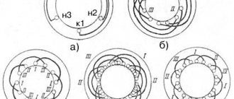
Diode bridge operation
Figure a) shows a conventional sinusoidal AC voltage. Figure b) shows cut-off positive half-waves obtained by using a rectifying diode, which passes the positive half-wave through itself and is blocked when the negative half-wave passes through. As can be seen from the diagram, one diode is not enough for efficient operation, since the “cut off” negative part of the half-waves is lost and the alternating current power is reduced by 2 times. A diode bridge is needed not only to cut off the negative half-wave, but to change its sign to the opposite one. Thanks to this circuit design, alternating current completely retains power. In Figure c) there is a pulsating voltage after current passes through the diode assembly.
A pulsating current cannot strictly be called constant. Ripple interferes with the operation of electronics, so to smooth it out after passing through the diode bridge, filters must be included in the circuit. The simplest type of filter is electrolytic capacitors of significant capacity.
On printed circuit boards and circuit diagrams, a diode bridge, depending on how it is constructed (individual elements or assembly), may be designated differently. If it consists of separately soldered diodes, then they are designated by the letters VD, next to which a serial number is indicated - 1-4. The letters VDS denote assemblies, otherwise -VD.
Selecting a build type
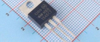
Using a rectifier bridge instead of four diodes not only greatly simplifies the assembly, but also makes the design more compact. The principle of choosing the type of assembly is the same - according to voltage, current and frequency. To determine whether, for example, the KTs402G assembly, the photo and diagram of which are given above, is suitable, you need to consult the reference book. It contains the following characteristics of the bridge:
- maximum reverse voltage of diodes - 300 V;
- direct current of the entire assembly - 1 A;
- cutoff frequency is 5 kHz.
The bridge is suitable, but the microassembly will operate at the limit of its current capabilities. To ensure the reliability of the circuit, it is better to use a more powerful device. For example, bridge KTs409A for a current of 3 A or KTs409I for 6 A.
How can I replace the diode bridge assembly?
Instead of a diode bridge assembled in one package, you can solder 4 silicon rectifier diodes or 4 Schottky semiconductors into the circuit. However, the diode assembly option is more efficient, thanks to:
- smaller area occupied by the assembly on the diagram;
- simplifying the work of the circuit assembler;
- uniform thermal conditions for all four semiconductor devices.
Various diode bridge assembly options
This circuit solution also has a disadvantage - if at least one semiconductor fails, the entire assembly will have to be replaced.
Rectifier device and connection diagram
The disadvantage of diode assemblies is that if at least one diode fails, then it will have to be completely replaced. This is the output of rectified, pulsating voltage. It transmits the overall power of the transformer as much as possible.
Its value increases and depends only on the resistance of the p- and n-regions. Theoretically, it is possible to convert an alternating voltage into a constant one using a single diode, but for practice such rectification is not desirable.
Thus creating a potential difference at the terminals of the same name. You can see how the diode cut off the lower, negative part of the voltage graph.
When a reverse potential is applied, the barrier value increases, since electrons leave the n-region and holes leave the p-region. But for the operation of devices with a constant power source, such a revolution is unacceptable. If one diode fails, the entire part must be replaced, excluding the possibility of removing one element.
The result will be a square, in the corners of which the following connections have been formed: anode, cathode - the input of one alternating voltage wire; anode, anode - negative potential output; cathode, anode - input of the second AC voltage wire; cathode, cathode - positive potential output. Composition of the rectifier module For anyone who would like to become more familiar with what a rectifier is, we advise you to take a short historical excursion.
So we have the famous NP junction, which passes current in one direction and the other in different ways. How to check a KBPC type diode assembly.
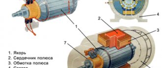
Why is a diode bridge needed in a vehicle generator?
Diode bridge in the generator
This circuit design is used in electrical circuits of cars and motorcycles. A diode bridge installed on an alternator is needed to convert the alternating voltage it produces into direct voltage. Direct current serves to recharge the battery and power all electrical consumers found in modern transport. The required power of the semiconductors in the bridge circuit is determined by the rated current produced by the generator. Depending on this indicator, semiconductor devices are divided into the following power groups:
- low-power – up to 300 mA;
- average power – from 300 mA to 10 A;
- high-power – above 10 A.
For automotive vehicles, bridges made of silicon diodes are usually used, which can meet operational requirements over a wide temperature range - from -60°C to +150°C.
Designation and marking
The conventional graphic designation of a semiconductor bridge on electrical circuit diagrams looks like a rhombus, from the tops of which straight short lines emerge, symbolizing the conclusions. Each pin is signed with a sign corresponding to the type of signal. Thus, a plus signifies a positive output, a minus signifies a negative output, and a tilde signifies inputs for supplying an alternating signal. In the middle of the diamond, a rectifying diode may or may not be depicted.
In the literature, various specifications and on diagrams, the device is signed with the Latin symbols VDS, followed by an Arabic numeral indicating the serial number. In foreign literature you can also find the designation BDS. There is no standard for bridge markings. Each manufacturer labels its products as it wishes, according to its own system.
If you carefully study the various symbols, you can trace a trend in the markings applied to the body of the device. It almost always contains data about its main characteristics. That is, the maximum current or operating voltage is indicated. For example, DB151S - the first two digits indicate the current 1.5 A, and the second voltage according to the table, in this case 50 V.
Domestic products are classified differently. The bridge itself is designated by the letter “C”, the number behind it indicates the material, and the subsequent numbers are the development number. For example, a popular bridge among radio amateurs that can withstand reverse voltages of up to 400 V is labeled as KTs407A.
How to replace a diode bridge in a generator
In most models of automobile and motorcycle equipment, bridge assemblies are soldered into an aluminum radiator, so if they fail, they will have to be desoldered and pressed out of the radiator plate and replaced with a new one. Since this is a rather complex procedure, it is better to avoid the occurrence of factors that cause the diode bridge to burn out. The most common causes of this problem are:
- liquid got on the board;
- dirt along with oil penetrated the semiconductors and caused a short circuit;
- changing the position of the contact poles on the battery.
Self-production
Single-phase rectifier bridges are usually not scarce radio components, so they can be purchased and selected according to the required parameters in almost any radio store. But you don’t always have time for this, so you can assemble the required bridge with your own hands. To do this you will need to prepare:
- Four diodes with identical characteristics. In principle, you can take any, but you should understand that the general parameters of the bridge will be determined by the weakest element.
- Installation wire.
- Soldering iron.
- Tweezers.
- Flux and solder.
- Side cutters.
- Electrical circuit of a rectifier diode bridge.
After everything is prepared, at the first stage the diode leads are tinned. To do this, the legs of the radioelements are lubricated with flux, and tin is transferred to them using a heated soldering iron, forming a thin layer. At the next stage, the diodes are connected according to the diagram.
To do this, you need to know where the element’s cathode is and where the anode is. In the diagram, the anode corresponds to the top of the triangle, and the cathode corresponds to the base. On the element itself, only the anode is indicated. This can be a stripe, a dot, or a conventional graphic designation shifted to one of the terminals.
Then two elements are taken and the anode of one is connected to the cathode of the other. A similar action is repeated for the remaining elements. The result is a pair, each of which consists of two diodes. Next, the cathodes are soldered together, and the anodes are soldered together. After the diodes are connected to the solder points, the conductors are connected to form the terminals of the device. At the last stage, the design is checked using a multimeter.
Using Op Amps
As is known, the current-voltage characteristic of diodes is nonlinear; by creating a single-phase precision (high-precision) full-wave rectifier on an op-amp chip, the error can be significantly reduced. In addition, it is possible to create a converter that allows you to stabilize the current on the load. An example diagram of such a device is shown below.
Circuit: a simple op-amp stabilizer
The figure shows a simple current stabilizer. The op amp used in it is a voltage controlled source. This implementation makes it possible to ensure that the current at the output of the converter does not depend on the voltage loss across the load Rн and the diode bridge D1-D4.
If voltage stabilization is required, the converter circuit can be slightly complicated by adding a zener diode to it. It is connected in parallel to the smoothing capacitance.
Briefly about controlled converters
It is often necessary to control the voltage at the output of the converter without changing the input. For this purpose, the most optimal would be to use controlled valves; an example of such an implementation is shown below.
Simple thyristor converter (on controlled valves)
How to organize bipolar power supply
By combining a balanced circuit and a bridge circuit, you can get a converter that will provide bipolar power at the output with a common (zero) point. Moreover, for one it will be negative, and for the other it will be positive. Such devices are widely used in power supplies for digital radio technology.
Diagram: example of a converter with bipolar output
Bridge rectifier or Graetz circuit
This drawback can be corrected by using a rectifying device in the form of a so-called bridge (Graetz circuit):
In this case, the first half-cycles will work, for example, diodes D2 and D4, and the second half-cycles - D1 and D3. At the load each time there will be a full half-wave of the secondary voltage:
The bridge circuit also has a less complex, lighter and cheaper transformer. As we will see later, it has several other advantages.
It is interesting that this circuit appeared historically earlier than the zero circuit, but was not widespread because, firstly, it had four diodes instead of two. However, the main thing was not their number, but the fact that during operation, every half cycle, the current passes through two series-connected diodes, onto which double voltage drops. At that time, there were no semiconductor diodes yet, and vacuum or mercury diodes had a significant voltage drop when direct current passed, which significantly reduced the efficiency. It turned out that a more complex neutral circuit transformer, but with one diode in the current rectification circle, is more economically profitable than a bridge circuit with double the number of diodes and double the energy consumption for them. And only the advent of relatively cheap semiconductor diodes with a very small forward voltage drop made it possible to turn to bridge circuits, which have now practically replaced the zero circuit (in this, if desired, one can see a manifestation of one of the dialectical laws - development in a spiral).
Checking the radio device
To check the bridge, you will need to take a digital device and switch it to diode testing mode. On a multimeter, this mode corresponds to the diode symbol. A black probe is connected to the tester into the COM socket, and a red one into the V/Ω socket. The essence of the test is to test the transitions. If pin No. 1 is the positive electrode of the device, No. 2 and 3 are the inputs for the alternating signal, and No. 4 is the negative output, then testing can be performed in the following order:
- Use the black probe to touch the first terminal, and the red probe to the third. A three-digit number indicating the transition resistance should light up on the tester screen. When changing the polarity, one (infinity) should appear on the display.
- The red probe touches the third terminal, and the black probe touches the fourth. The tester should show infinity, and when the polarity changes, a three-digit number should appear.
- The black wire is connected to the first leg, and the red wire to the second. The device should show a transition resistance; if the polarity changes, it should show a break.
- The red wire is connected to the third pin, and the black wire to the fourth. The transition should not ring. When changing the position of the wires, the tester should show resistance.
You may be interested in Calculation of ground loop resistance in private homes
If all four points are met, then we can assume that the rectifier is assembled correctly and is in working condition. In this case, any semiconductor bridge can be tested in this way.
Rectifier
The voltage obtained after the diode bridge has the shape of a sinusoid, in which the negative component is reflected relative to the time axis. In simple terms, it is shaped like hills and is called pulsating. This voltage is positive. Does not contain moments when current does not flow. But it is still unstable. For example, at point “a” it is early 0 volts, and at “b” it has a maximum value. This rectifier cannot be considered complete.
To solve this problem, a smoothing electrolytic capacitor is required. On the board it is usually located in the same place as the diode assembly. The capacitance accumulates energy at those moments when it has peak values (point b), and releases it at moments of dips (a). The output is a straight line - full-fledged direct current, suitable for powering subsequent electronic components, processors, microcircuits, etc.
The simplest rectifier
Figure 2. Current characteristics in various circuits.
The current flowing in a conventional lighting network is variable. Its magnitude and direction change 50 times within one second. A graph of its voltage versus time is shown in Fig. 2a. Positive half-cycles are shown in red, ? negative.
Since the current value varies from zero to the maximum (amplitude) value, the concept of the effective value of current and voltage is introduced. For example, in a lighting network the effective voltage value is 220 V? in a heating device connected to this network, the same amount of heat is generated over equal periods of time as in the same device in a 220 V DC circuit.
But in fact, the network voltage changes in 0.02 s as follows:
- the first quarter of this time (period)? increases from 0 to 311 V,
- second quarter of the period? decreases from 311 V to 0,
- third quarter of the period? decreases from 0 to 311 V,
- last quarter of the period? increases from 311 V to 0.
In this case, 311 V? voltage amplitude Uо. The amplitude and effective (U) voltages are related to each other by the formula:
When a series-connected diode (VD) and load are connected to an alternating current circuit (Fig. 2b), current flows through it only during positive half-cycles (Fig. 2c). This happens due to the one-way conductivity of the diode. Is such a rectifier called half-wave? During one half of the period there is current in the circuit, during the second? absent.
The current flowing through the load in such a rectifier is not constant, but pulsating. You can turn it almost constant by connecting a filter capacitor Cf of a sufficiently large capacity in parallel with the load. During the first quarter of the period, the capacitor is charged to the amplitude value, and in the intervals between pulsations it is discharged to the load. The tension becomes almost constant. The greater the capacitor capacity, the stronger the smoothing effect.
Operating principle of a full-wave circuit
Let's consider two options for implementing a full-wave converter (rectifier): balanced and bridge. The diagram of the first is shown in the figure below.
The simplest uncontrolled balanced converter using two diodes using a transformer with a middle output
Elements used:
- Tr is a transformer that has two identical secondary windings (or one with a tap in the middle);
- DV1 and DV2 – valves (diodes);
- Cf – capacitive filter;
- Rn – load resistance.
For clarity, let us immediately present an oscillogram at control points.
Diagram of a balanced type device
- U1 – input oscillogram;
- U2 – graph in front of the capacitive filter;
- Un – diagram at the device output.
This circuit is two combined half-wave converters, that is, two separate sources account for one common load. The result of the operation of such a device is clearly demonstrated by graph U2. It shows that both half-cycles are used in the process, which gives these converters their name.
The oscillogram clearly demonstrates the advantages of such a device, namely the following facts:
- the ripple frequency at the device output doubles;
- reducing the “dips” between pulses allows the use of a smaller filter capacitance;
- A push-pull converter has greater efficiency than a half-wave converter.
Now let's look at the bridge type, it is shown in the figure below.
Diagram: Example of using a diode bridge
The oscillogram of a bridge type device is practically no different from a balanced one, so there is no point in presenting it. The main advantage of this scheme is that there is no need to use a more complex transformer.
Video: Full-wave rectifier bridge
Converters that use a semiconductor diode bridge are widely used both in electrical engineering (for example, in welding machines, where the rated current can reach up to 500 amperes) and in radio electronics, as a source for low-current circuits.
Note that in addition to semiconductor diodes, you can also use vacuum diodes - kenotrons (an example of a circuit diagram of such a device is shown below).
Scheme: converter based on a 6Ts4P two-anode kenotron
Actually, the presented circuit is a classic implementation of a full-wave balanced converter. Today, vacuum diodes are practically not used; they have been replaced by semiconductor analogues.
Half wave converter
Below is a typical diagram of such a device with a minimum of elements.
Read also: Adjusting the oil supply on a calm chainsaw
Scheme: the simplest converter
Designations:
- Tr – transformer;
- DV valve (diode);
- Cf – capacitance (plays the role of a smoothing filter);
- Rn – connected load.
Now let's look at the oscillogram at control points U1, U2 and Un.
Oscillogram taken at control points U1, U2 and Un
Explanation:
- control point U1 displays a diagram taken at the device input;
- U2 – diagram in front of the capacitive smoothing filter;
- Un – oscillogram at the load.
The timing diagram clearly shows that after the valve (diode), the rectified voltage is represented in the form of characteristic pulses consisting of positive half-cycles. When such a pulse occurs, the charge of the capacitive filter accumulates, which is discharged during the negative half-cycle, this allows the pulsations to be somewhat smoothed out.
The disadvantages of such a scheme are obvious - it is low efficiency, due to the high level of ripple. But despite this, devices of this type find their use in circuits with low current consumption.
How to implement voltage doubling
Below is a circuit that allows you to obtain a voltage at the output of the device that is twice as high as the original one.
Voltage doubling circuit
It is typical for such a device that two capacitors are charged in different half-cycles, and since they are located in series, then, as a result, the total voltage at “Rn” will be twice as high as at the input.
In a converter with such a multiplier, transformers with a lower secondary winding voltage can be used.