How much does it cost to install a doorbell?
Prices
| Type of work | Unit | Price |
| Doorbell Installation | PC. | 400 rub. |
| Removing the doorbell | PC. | 100 rub. |
| Installing a doorbell away from the entrance | PC. | from 1500 rub. |
| Minimum visit of a technician | 1500 rub. |
Interesting materials:
How long should you keep the curlers on your hair? How long should Hexicon candles be kept on? How long should you keep the toner on? How long does it take to ferment Ivan tea? How long does it take to cook squid? How long does it take to cook French fries? How long does it take to go to driving school? How long does it take to smoke cold smoked fish? How long does it take to smoke salted lard? How long does it take to dye the roots?
Electric bell
Details Category:
ELECTRICAL BELL
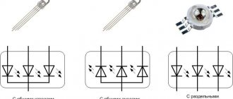
, a device for producing bell signals using electric current. Electric bells are divided into two classes: direct current bells (galvanic) and alternating current bells (polarized).
DC bells are used for signaling purposes over short distances and in home telephone sets with battery-operated calling. The basic, most common call scheme (Fig. 1) operates as follows. When button K is pressed, the current from the battery passes through the winding of the electromagnet E and the contact of the breaker P. The armature I is attracted and breaks the contact, as a result of which the magnetization stops and the armature returns to its original position, closing the contact, the electromagnet E is excited again, and the process is repeated until Pressing the K button will not stop.
For more reliable operation, the contacts are made of silver or platinum. The design of electric bells varies greatly, depending on the desired sound strength and installation location. The most common is an electric bell with a cup d = 70mm, R = 20 Ohm and I = 100 mA. Two elements of the Leclanche type, or dry ones, are used as a current source. In connection with the spread of alternating current (50 periods) for lighting, the power supply of galvanic bells from the lighting network through step-down transformers (120 x 4V) is increasingly coming into use.
Polarized electric bells of alternating current (15-50 per.) are used for signaling over long distances and in all telephone sets of the local battery (MB), central battery (CB) and automatic telephone exchange (ATS). The principle of their design is as follows (Fig. 2).
C and C1 are soft iron cores, K and K1 are coils whose turns are directed in opposite directions; I am an anchor made of soft iron, rotating on centers and having a hammer M; N and S are the ends of the permanent magnet. When passing alternating current through the windings, the polarity of C and C1, caused by a permanent magnet, will change, weakening at one pole and strengthening at the other. Thus, the anchor will be pulled from one pole to the other, alternately hitting the cups. The cups are made of different thicknesses, adjustable to thirds, and the mounting holes are made eccentrically to facilitate adjustment. Polarized electric bells are very sensitive, give a loud, clear signal and are stable in operation, due to the absence of a breaker. Their sizes vary, as do their designs. The table shows some data on polarized electric calls.
Source: Martens. Technical encyclopedia. Volume 8 - 1929
- < Back
- Forward >
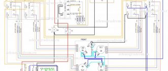
Connection diagram
To install a wired electric bell yourself, you will need:
- electric drill or hammer drill;
- indicator screwdriver;
- pliers;
- screwdrivers with a thin tip;
- wire cutters
In addition to the above, you should have:
- the electric bell itself;
- button to turn it on;
- a pair of two-wire wires.
This is what brief instructions for connecting a call look like.
To carry out installation, prepare an electrical wire that includes two wires with a cross-section of 0.5 to 0.7 square meters. mm. Since the electric bell has little power, using wiring with a large cross-section will be irrational.
In addition, take into account that the material from which the cores are made can be copper or aluminum. Select a wire that contains the same cores as all residential electrical wiring.
All wiring that enters the junction box above the front door must be disconnected from the electrical supply.
Wiring:
- one is stretched from the box to the electric bell, the other is also from the box, only to the button, the far ends of each wire are connected to the button and the bell;
- wires are connected in the box according to the diagram.
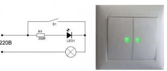
As you can see, the diagram exactly reproduces a typical electrical circuit for connecting a switch. Specifically, “0” is connected to the bell, and the phase wire goes to the button, which is similarly connected to the electric doorbell. In other words, there is a phase break in the button, at the same time, by pressing the button, you close the electrical circuit, and the bell makes a sound. If this wired electric bell is connected to a simple 220 V socket, it will ring until the power supply is available.
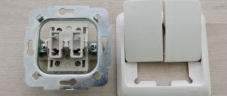
Sometimes a consumer discovers not two, but four terminals in a purchased device. Most people do not understand exactly how to connect the wires. The manufacturer, for its part, decided that it would be simpler (in fact, it’s completely the opposite). In this situation, you should refer to the connection diagram.
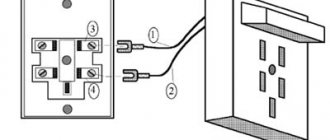
Here the bell itself is designated as a junction box. Wires from the button and two wires powered by a voltage of 220 V are connected to it.
Another scheme is practiced - when the bell is fed through a transformer. As a rule, this method occurs when the button is made of metal. For the sake of electrical safety, it is powered with low voltage - 8 V, 12 V or 24 V. In order to implement this scheme, a bell with low voltage control is required (it is better to ask the seller about this in advance).
A transformer for an electric bell is placed in the electrical panel, the dimensions of which are similar to a circuit breaker. A low-voltage wire is pulled from it to the junction box, after which it is connected to the wiring of the button and the bell.
A video review of wired doorbells is presented below.
Mechanical bell
To notify owners of the arrival of someone, a mechanical type of door signal is extremely rare today. It is used by those who like to decorate the exterior of their home in English, colonial, country genres, or in retro style.
It is often used for decorative purposes when decorating the front door. Such calls represent the simplest design and are quite easy to install. Mechanical products last much longer than their innovative counterparts.
Musical call
This device is the simplest and most economical of all those published in the literature. Basically, such a bell is intended for use as an apartment bell, although it can also find other applications, for example in toys or as an alarm clock bell.
The circuit is based on the BT66T-2L music synthesizer microcircuit (Fig. 1). Inside it has an RC oscillator and a melody generator, which consists of 127 notes and repeats periodically. Elements C1, R2, VT1, VT2 set the sound operating time, and VT3 is the power amplifier. The last transistor is installed only if you need to increase the volume of the sound emitter (BA1 can be connected directly to the output of the synthesizer, as shown by the dotted line).
Rice. 1. Electrical circuit of a musical bell
After pressing the SB1 button, the signal sound time depends on the capacitance C1 and the resistance R2 (with the values indicated in the diagram, it is approximately 2.3 s). If desired, you can increase the playing time by increasing C1.
Power is supplied from two 1.5 V galvanic elements. In standby mode, power consumption is almost zero, since all transistors are in the off state (will be equal to the leakage current of capacitor C2), so a switch is not required.
Rice. 2. PCB topology and arrangement of elements
To install the elements, you can use the printed circuit board shown in Fig. 2. Any details will do.
Malyshev S.Yu. Mariupol
Setting up a call
Any doorbell model is not difficult to install yourself - no adjustment is required, except for selecting the desired melody.
Wires for electrical wiring
The easiest way is to install a wireless bell on your front door. Most often, such structures are attached with double tape, so all the work comes down to choosing the installation location. It may be necessary to remove the factory protection from the installed battery. New batteries and accumulators must be installed strictly observing polarity.
Important! Although the design of the button, according to manufacturers, is sealed, it is worth taking care that water does not get on the block. This applies not only to wireless calls, but to all others.
A wired bell requires provision for laying connecting wires between the push-button and bell parts. Usually there are no restrictions on the length of the wires, but you should not use very thin ones, as this may adversely affect their reliability. Before installing the wired structure, you should carefully read the installation instructions and the labels on the connection terminals on the bell.
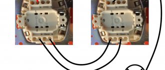
Connecting a simple call
When a wired bell is installed near the front door of an apartment, it is possible to install parts of the bell opposite each other on opposite sides of the wall. This option is the simplest, since the wires from the button pass through a hole in the wall directly to the signaling device. Additionally, wiring to the junction box or power outlet is required. During repair work, it is necessary to provide grooves for laying wires, otherwise you need to use a plastic cable channel. Before connecting wires to the network, it must be de-energized by turning off the automatic power switch on the power panel.
Important! If you are repairing or installing a doorbell on an older direct AC power system, care must be taken when routing and securing the wires. Insulation should not be violated anywhere. It is also important to ensure that the neutral and phase conductors of the installed bell are connected correctly.
The most practical design is wireless residential calls. Firstly, they have the simplest connection, and secondly, they do not require a separate power supply. The radio call is so easy to install and adjust that even a completely untrained person can handle it. Installing and configuring more complex designs, such as video calls, especially those running over GPRS or Wi-Fi, requires some experience and practice.
Types of calls
Based on the principle of ring signal formation, a wired bell can have the following designs:
- electromechanical calling devices;
- electronic calls.
Electronic devices may have a volume control located on the front panel, which allows you to change the level of the signal entering the built-in speaker.
Electronic call
Differences in the operation of electronic and electromechanical samples are manifested in various mechanisms for converting and delivering a ringing signal. In addition, according to the method of transmitting the information package, electronic calls are divided into wired devices and their wireless analogues (radio-controlled models). Depending on the type of signal that provides the user with information about the call, they can be audio or visual (the latter category refers to video recorders). Based on their location, all existing models of electric calling devices are divided into street and indoor calls.
Installation features
Indicator screwdriver
The procedure for installing the elements of the calling device depends on its modification and configuration, which are considered for each option separately. In any case, before starting work you will need to prepare the following tool:
- indicator screwdriver;
- an ordinary screwdriver;
- side cutters - necessary for cutting off the conductor to the required length.
From the materials you need to prepare miniature adapter blocks with slots for a screwdriver and two pieces of wiring of the required length.
Wired Device Installation
Installation of the electric doorbell housing Zamel bim Bam
Wired doorbells are installed at their place of work in the following sequence:
- It is necessary to de-energize the apartment by turning off the input circuit breaker.
- A box with an electronic circuit is taken, from which two white conductors come out, and hung on screws screwed into the wall.
- It is necessary to connect one end of the wire using a miniature adapter block to a brown conductor supplied from the phase terminal of the input panel or distribution box.
- The second end, using the same block, is connected to a long piece of wire laid along the wall to the calling button and connected to one of its terminals.
- After this, from the second push-button contact, the same conductor is laid next to the first one to the zero terminal of the distribution box or switchboard.
At the final stage of work, all that remains is to turn on the introductory machine and check the call for functionality
When checking the signal chain, you need to act carefully, constantly remembering that when the button is not pressed, one of its terminals is under voltage of 220 Volts. You can check its absence or presence using the indicator screwdriver prepared earlier.
Wireless device
Wireless call with two buttons
In the case of a wireless device, the installation operations look like this:
- At a selected location in the apartment, a box with a receiver is mounted on the wall, powered by a battery previously installed in it.
- A signal transmitter, designed in the form of a panel with a button, is fixed on the jamb of the front door, which also requires a built-in battery.
- To test the call device, press the call button and listen to the sound signal.
- If there is a volume control, you need to make sure that it works properly.
If the receiving device is powered from the mains, you should connect its terminals according to the color marking: the red or brown wire to the phase contact in the distribution box, and the blue wire to the neutral terminal.
If the receiver does not function for some reason, you need to replace the batteries again in case there is a bad contact at the place where they are connected.
There is no need to turn off the electricity when connecting the battery-powered wireless bell, since it is not in use.
Electric doorbell design
In order to understand the structure of this simple device, you need to familiarize yourself with the main components of its design.
The doorbell consists of:
- module responsible for supplying electricity;
- buttons;
- contact group;
- springs;
- anchors;
- hammer;
- electromagnet.
The latter is the main element, without which signal transmission will not take place. To close the power circuit, you need to press the doorbell button located outside, next to the front door. The load passes through the wires to the block with the speaker - a sound signal is heard. An electromagnet is involved in closing and opening.
Video call
Innovative technologies make doorbells equipped with a video camera popular today. The mechanism consists of several elements - a communication channel, a power supply, an electronic device for visual display, which is displayed on a TV or computer screen.
The reasons for setting the video signal are factors such as:
- Wide installation access;
- The ability to communicate with an interlocutor at a distance;
- Ease and convenience of operation;
- Remote use;
- Possibility of battery operation;
- Availability of various remote functions;
- The presence of a volume control.
In addition to calls made via video communication, the electronic equipment market offers such a model as a smart doorbell.
Power supplies[edit]
Electric bells are typically designed to operate at low voltages ranging from 5 to 24 V AC or DC. Before the widespread use of electricity, bells were necessarily powered by batteries, either wet or dry cells. [2] The bells used in early telephone systems received current from a magnetic generator started by the subscriber. In residential settings, a small bell transformer is usually used to power the doorbell circuit. To allow bell circuits to be created using inexpensive wiring methods, bell signal circuits have limited voltage and power ratings. [3] Bells for industrial purposes may be operated at other, higher AC or DC voltages to match plant voltages or available battery backup systems. [4]