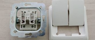
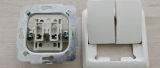
What does a pass-through switch with 2 or more places look like?
This is the minimum number of devices that can be connected to the system so that the user can turn one lamp on or off. In practice, such devices are used to turn on the lighting at one point, walk a certain area in comfort, and turn off the light at another point without going back. An example of a wiring device for a residential premises from the category of standard projects.
However, projects at control points are used quite actively. When you subsequently switch any of the switches, in any order, the lamp will turn off and on. As mentioned above, in the absence of a diagram, it is better to call the contacts at different positions of the key.
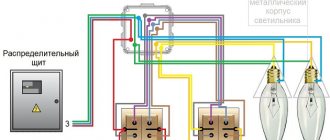
That is why the question arises, how to make it possible to turn on a light bulb from two or more places at once? Share with friends: You may also be interested. Let's consider the principle of operation of these devices according to the following photo: In this circuit, the following is mounted: power supply B phase and zero; distribution box in which switching is performed; 2 groups of lighting circuits, for example, this could be a chandelier and LED lighting in a hall or room. Control circuit for two separate lamps from four points As we have already noted, the lighting control circuit can be expanded endlessly. Of course, an additional wire can be laid in a cable channel or using a cavity in a plastic baseboard. As for cheap Chinese switches, basically there is no such circuit, so you have to connect the ends with a device. Automatic turning off of the light when leaving a certain area can be organized using timers or sensors that record movement.
Connecting a pass-through switch
The differences are in the number of contacts. The switch works as follows: when switching with a key, the input is connected to one of the outputs.
All neutral and all protective wires are connected to two separate connectors. Multi-element schemes, of course, are of little use for the private residential sector, since projects of this kind rarely have long corridors or large rooms with several doors. Review of pass-through switch manufacturers: popular models Before you buy a pass-through switch, you should get acquainted with the leading manufacturers who produce the highest quality products. Let us next consider what the connection diagram for a pass-through switch from 2 places should be, since this is considered the most common option for implementing lighting systems in houses, apartments or offices. In such situations, it becomes necessary to control lighting from two places; it is for solving such problems that the so-called pass-through switches are designed. The solution is made taking into account the wiring of the cable with the PE grounding conductor. In this case, we are talking about including a cross switch in the circuit, acting as an additional link. In this case, you can use the 4-point connection diagram for pass-through switches. After pressing the first button, the light will go out.
In the junction box we connect the corresponding wires of both switches. With this solution, it is already possible to walk through a long corridor halfway, turn off the lights on the completed half and turn on the lights on the remaining half. Review of pass-through switch manufacturers: popular models Before you buy a pass-through switch, you should get acquainted with the leading manufacturers who produce the highest quality products. There is no provision for an intermediate position in this case. A parallel switch, unlike a pass-through switch, contains as many as 5 contacts, which provide a more complex lighting control circuit, which has a much larger number of options. How to connect a pass-through switch
https://youtube.com/watch?v=3yLQJbjN8Eo
Connection diagram for two switches
Installing such a circuit on one light bulb is not difficult. At the stage of creating the wiring at the points where the installation of changeover structures is planned, it is necessary to lay a three-core cable in advance before the first two. If you need more light switches, then you will have to use a four-core cable, which must be stretched to the next ones.
To be able to control the lighting from two places simultaneously, you need to purchase pass-through switches, which are equipped with two switching positions and three contacts. In this case, the switching must be of a reversible nature, with the first node being common to the other two.
Components and devices
When considering the “two switches for one light bulb” circuit, which has two changeover switching structures, we can distinguish the components:
- connection (branch) box, which is used to protect electrical connecting cables - present in every room; in large rooms several of them are installed;
- connecting wires (two-, three- and four-wire);
- the lamp itself;
- two pass-through switching devices.
Principle of operation
Installation of a pass-through lamp switch:
- The “zero” wire is laid from the source to the branch box, then goes to the lamp.
- The “phase” wire is drawn from exactly the same source to the same box, and then laid to the common contact of the first switch.
- Using a junction box, the two changeover contacts of the first switch are connected to exactly the same parts of the second switch.
- The phase from the common contact of the second switch is connected to another electrical unit of the lamp.
The installation work of a control system for one lighting fixture operating from two places simultaneously is not complicated.
Installation is carried out as follows:
- Install reversible switching structures in the required places.
- Do not remove three-core cables from them.
- Install one or, if necessary, several electric lamps connected in parallel to each other.
- Remove a two-core cable from one or several lighting fixtures.
- Install the junction box, the location of which corresponds to convenient access to it and the shortest distance of the cable length.
- Connect the wires from the changeover structures, power supply and the lighting fixtures to the box.
- Connect them as described in the above paragraphs.
Two-key switch and its connection, diagram and photo
In a room with several lighting fixtures or a chandelier with several bulbs, you simply cannot do without a two-key switch, which allows you to regulate the lighting level in a certain way: one or more light bulbs can be connected to each key. We will look at connection diagrams for two-key switches for two or more light bulbs.
In addition, this is a more compact solution than installing several conventional switches. By pressing one key, we turn on one light bulb (lamp) or a specified group of light bulbs (lamp); the second key is “responsible” for other lamps or lamps; Pressing both keys turns on all lighting. As you can see, everything is simple.
However, installing a double switch can be understandably confusing. More precisely, its connection to the network. Therefore, now we will analyze the whole process in more detail.
The principle of operation of a switch with two keys is simple: the live phase wire is connected alternately or simultaneously to both wires leading to electricity consumers by closing the terminals, providing the result described above. The prepared ends of the wires (exposed to a sufficient length) are connected to the terminals using screws or special clamps.
Let's get started installing a switch with 2 keys
Connecting electrical appliances, including switches, must be done in conditions of good daylight and always with a previously de-energized network.
Please note: first, be sure to turn off the power supply!
In addition, the necessary tools - Phillips and flathead screwdrivers, pliers - must have insulated handles. You will also need a sharp knife and high-quality electrical tape.
First you need to draw a wiring and connection diagram and lay out the wiring, after which you can start working on the switches themselves.
The wiring is laid openly (on top of the wall) in special corrugated pipes or in a closed way (internal wiring) in grooves specially made in the wall, which are then plastered. Wire connections are made in special junction boxes.
Three wires should go directly to the switch:
- one incoming, phase wire, to which voltage is applied - it is determined using a special probe screwdriver, for which you need to turn on the electricity, and after the phase wire has been identified and marked in a convenient way, the network must be de-energized again;
- two outgoing ones, leading to consumers (light bulb sockets in lamps).
Connection
Thoroughly strip the ends of the wires of insulation, about 1 cm. If the wires are multi-core, press off the exposed part with a special crimper.
Carefully inspect the terminal block: the input terminal near the hole where the wire is inserted is marked with either an arrow or the Latin letter “L”. If the input terminal is marked with a letter, then the output terminals, in turn, are marked with arrows.
Connect the output wires to the appropriate terminals - as a rule, the end of the wire inserted into the hole is pressed with a screw using a screwdriver. At this stage, you can decide which lamps (light bulbs) will be turned on/off with which key by connecting the corresponding wires to the right and left terminals.
Next, in the same way, we connect the phase wire into the input hole and insert the switch into place in a special socket box, evenly pressing the right and left screws of the side stops. Then we replace the keys and check the operation of the assembled circuit.
Two-gang switch with backlight
Two-button switches with dimmers (backlight) are very convenient for searching in a dark room, especially if the switch is not located right next to the door, but in another place in the room. In order for the backlight to turn off, it is enough to connect one of the two wires leading from the indicators mounted in the keys at the top to the phase contact, and connecting the one coming from the bottom to one of the contacts going out to consumers. As you can see, there is nothing complicated in this question either.
By following our instructions and being extremely careful, you can connect several lighting fixtures and other electrical devices via a two-key switch.
Features of a double switch for two light bulbs
Models with multiple keys are used to optimize electrical equipment that comes from a single circuit. Usually a double switch is installed for the bath and toilet, which are separated by a wall. A device is placed on the hallway side and another one is placed inside the bathtub. Thanks to this, one element performs several actions at once: it turns on the lamps in one room and turns it off in another.
A common device with 2 light bulbs is installed only in rooms that are located closely. If they are separated, then it is much more convenient to take several elements. Installing a double switch is advisable when using a sconce or chandelier with two bulbs. This makes it possible to regulate: the first button turns on the weak light, and the next one increases its intensity.
If you plan to connect a double switch to several rooms, then this will not only save electricity, but also reduce the amount of installation and building materials.
General information
Before connecting two light bulbs to one switch, it is necessary to consider in detail its structure, operating principle, as well as the main advantages and disadvantages. This information will help you choose the most effective installation scheme that is ideal for a specific room.
Device and principle of operation
A double switch is considered the most universal, as it allows you to control the operation of 2 light bulbs or lighting fixtures. Despite this efficiency, the device consists of a minimal number of parts. Among them the following stand out:
- Two removable keys. They can only move in one plane, due to which the light source is turned on and off.
- Collapsible body. It consists of a main part and a facing panel, which performs a decorative function and also hides all errors made during installation.
- Terminal blocks. These important structural elements are used to connect the switch to the supply wires.
The operating principle of a two-key switch is as simple as possible. It can be easily understood not only by a qualified electrician, but also by a beginner who connects this structure for the first time. The principle of operation is the ability to control the degree of illumination.
Possible options:
- Enables only the right key. It illuminates the part of the room in which the connected light source is located.
- Enables only the left button. In this case, half of the room will be illuminated.
- Simultaneous pressing of two keys. All connected lighting fixtures will immediately begin their work.
Advantages and disadvantages
A double switch, like any other similar device, has several advantages. Thanks to them, it is popular among consumers and is often installed in various rooms.
The advantages of such a device are:
- Ability to control multiple lighting fixtures. Thanks to the presence of two keys, the switch can simultaneously control two light bulbs and turn them on when necessary.
- The ability to adjust the brightness of the lighting in the room. This opportunity appears when you connect the device to different lamps or chandeliers. By pressing one of the keys, not the entire lighting fixture will be turned on, but only a few of its light sources.
- Controlling the presence of light in two separate rooms. If you connect correctly, you can turn on and off the lights in different rooms with one device.
- Economical. In some cases there is a need for a minimum of light, so you can use only one key. This will help eliminate unnecessary energy consumption, which will significantly reduce financial costs.
- Rational use of wires. With proper connection, you can reduce the amount of cable used and place it in the most convenient place.
- Easy to install. The product is easy to install using a minimum number of tools and consumables.
- Cheapness. A two-key switch costs about the same as a single-key switch. Consequently, additional financial costs will be minimal.
The disadvantages of such switches are:
- Impossibility of installation outdoors. The standard design does not have sufficient insulation from rain and other natural disasters.
- More frequent light bulb burnouts. This only happens in cases where the owner of the premises constantly selects the desired lighting by alternately turning on and off the light sources.
- Lack of ability to upgrade the device. The switch cannot be equipped with additional functions that help regulate the light.
https://youtube.com/watch?v=RWI_-tMXtDA
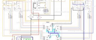
Connecting a chandelier with additional equipment
Now about connecting the chandelier in which the fan is mounted. This lighting device does not require anything special to connect, since the fan is the same consumer as a regular light bulb (that is, the circuit is the same as that of a two-arm chandelier).
It should be connected to a two-key switch so that you can turn off the light or fan if necessary.
Also, when connecting such a chandelier, you should read the instructions, which should indicate which of the wires going to power the fan is phase and which is neutral, and use this information when connecting.
The same applies to chandeliers that have remote control using a remote control.
Inside such a device there will be a special executive unit with a controller that receives signals from the remote control.
So, this unit requires power, and it works on the same principle as a light bulb.
But in chandeliers with LED lamps, the lighting elements operate from a 12V network with direct current. And for this purpose, the design of the lighting device contains a step-down transformer, which has phase and neutral terminals.
Connecting this chandelier is as easy as connecting a regular light bulb.
Sometimes there is a need to install a combination switch to power the chandelier, combined with an outlet.
NShVI lugs for crimping wires: sizes, types, how to crimp, other types of TML, NVI and NKI
And here the whole peculiarity lies precisely in connecting the switch itself, and not the lighting device.
Since there is an outlet, in order for it to function, both phase and zero must be supplied to it.
And if only a phase conductor was routed to a conventional switch, then a neutral conductor will also have to be routed to the combined switch. The connection diagram for such a switch is presented below.
There are times when the part of the supply wiring protruding from the ceiling is not enough to connect the chandelier. In this case, you can simply increase them.
To do this, you can take two pieces of copper wire with a cross-section of at least 1.5 mm. sq. and connect them to the line terminals using twisting. Then the connection points should be properly insulated.
Popular with readers: Criteria for choosing a cordless screwdriver, disadvantages and advantages of the device.
Two-gang switch
The principle of operation is the same as in the case of the single-key model. When can it be connected:
- on lighting fixtures with multiple arms to control lighting modes;
- installation next to separate entrances to the bathroom and toilet;
- when you need to save space on the wall.
The neutral and phase wires are supplied to the installation box. If they are not color coded accordingly, you can determine their purpose by using an indicator screwdriver. To complete this procedure, it is enough to touch each of the cores with the tool. Touching zero will not cause a reaction from the indicator on the screwdriver. The appearance of a glow indicates contact with the phase. Mark the phase by carefully placing a piece of insulating tape on top.
Separate lighting
The switch is installed in the place where the phase is broken. Each device has three contacts for two keys: 1 input, and two more are assigned to the output. The phase needs to be connected to the switch, from there it is output to the light bulbs, passing through the desired key.
Since each light is connected to a specific key, the lighting is called "split". The conductor with “zero” will be common. From the mounting box it goes to each light bulb individually.
Connecting a chandelier with multiple arms
To organize this type of connection, you will need a conductor with 3 cores. One of them needs to be made short enough so that it fits into the mounting box. The other two need to be connected to the switch. These 3 wire strands located in the socket box should be stripped using a knife. Use a knife to scrape off the insulation on each side of the core by 1 centimeter. Further:
- Connect one of the wires to the input pin on the switch. The other end must be connected to the phase coming from the power supply.
- Connect the remaining two wires to the output contacts on the switch. Their other ends should go to the phases on the lamps.
- After this, the working frame of the switch can be installed in the socket box. Tighten the screws and install the protective part: frame and buttons.
- Look inside the mounting box again. Connect the neutral coming from the light bulbs to the neutral on the power supply.
- In the sockets on lighting devices you can find 2 contacts. Zero goes to the side. The central one is needed to connect the sockets on the chandelier to the phase.
- Make sure the contacts are reliable and the assembled circuit is correct. To do this, release voltage through the apartment by activating the machine. The switches must be set to the “disabled” position before doing this.
- Turn the switches on. Check whether the light bulbs respond to the control key.
- Turn off the power to the circuit breaker.
- Take some insulation tape. Wrap the twisted wires in the wiring box in insulation. For greater reliability, special thin PVC tubes can be installed on top.
There are also variants of similar devices with three keys. They are usually connected in shopping centers. The connection diagram looks a little more complicated, but the process follows the same principles.
Connection diagram to a switch with socket
You can connect the switch to an already installed outlet. To do this, you will need 3 wires - zero and 2 phases.
If the light source is located next to the outlet, then “zero” can be output directly from it:
- Determine the purpose of the cables.
- Disconnect the network.
- Take the vein. Connect one end of it to the phase on the socket. Attach the other one to the input of the switch.
- Connect the other wire as follows. Bring one end to zero. The other is to the output on the lighting device.
- Lay out the wires, insulate them and apply voltage.
If the lighting device is located far enough, then it is more advisable to draw a “zero” from the distribution box. This will allow you to better manage the length of the wire and will ultimately look better. In this case, only the phase will be taken from the outlet:
- Turn off the voltage.
- Open the outlet and make sure there is no current in the system.
- Attach a wire to the outlet phase of the socket. Let it be connected to the input on the switch. In this case, lead the wire from the output directly to the light bulb.
- Find the "zero" in the wiring box. In its place you can find a whole tire.
- Connect one end of the wire to it, and the other to the side contacts of the lighting devices.
- If there is a ground on the lamps, connect it in the same way to the corresponding contacts in the junction box.
- At the end of the process, check the quality and success of your work.
Connection from an outlet
But there are times when it is necessary to connect an additional lamp with a separate switch. Then it is possible to install wiring from an existing outlet. It makes no sense to discuss the choice of method of management (external or internal) now; this is not relevant to this topic. It is more logical to consider connection options. When installing a single-key switch, no difficulties arise; you only need a two-wire wire and the switching device itself.
If the voltage breaker is installed above the socket, then the neutral and phase wires are removed from it. The phase is interrupted inside the switch, while the zero remains intact. The rest of the lighting equipment connected to the circuit is powered according to the above circuits.
Connection diagram from the socket
With a similar installation of a two-key switch, three wire strands are required (output - zero, phase, phase), and if the breaker has three keys, then 4 wires are needed (zero and 3 phases).
Connection diagram for a simple lamp
Using the example of the simplest single lamp, the “Ilyich bulb,” we will consider the main elements of the electrical circuit.
In any apartment, wiring is usually laid in the wall along the perimeter at a distance of about 10-15 cm from the ceiling. This is a highway. Branch boxes are installed on it. They are needed in order to “crash” into the main cable and power a socket or switch with a lamp.
Let's look at the wiring diagram in the junction box. The cable goes down from it to the switch, up to the lamp, and to the left and right - the main cable. In fact, this is, of course, a convention; the order in which the wires are inserted into the box is determined only on the basis of considerations of expediency.
Neutral wire, easy to use. It branches directly from the main line and goes straight to the lamp. The situation with the phase wire is not much more complicated; it also goes to the lighting fixture, but only through the switch. That's all the wisdom.
A regular single-key switch has two contacts on the back for connecting wires. In this case, polarity does not matter. How to connect a chandelier to two switches? Will the task become much more difficult?
Main conclusions
Now you know how to connect two working light bulbs to one switch. The exact connection method depends on additional nuances. However, the general principle of action is the same: it is necessary to follow safety rules and connect wires of the same type.
Situations where one switch controls two lighting fixtures at once occur quite often. The only difference is that sometimes it is necessary to operate both lamps simultaneously with one switch, while in other cases it is necessary for each lamp to light up separately. This means that in the first case we will need a single-key switch, and in the second we will have to install a device with two keys. Let's talk about each of them separately and consider in detail how to connect two light bulbs to one switch.
The ability to connect two light bulbs to one switching device at once allows you to save materials, time and effort, because you don’t have to install a second switch, lay extra wires, or drill additional holes and grooves in the walls.
Connecting one lamp to a single-key model
Let us describe a method for connecting a light bulb to a switch with one control button. Some types of symbols indicated on the device:
- if number 1 is marked, this is an input phase contact, number three is marked as an outgoing phase contact;
- letter designation L – incoming phase contact, number 1 – outgoing phase;
- L – input, arrow – exit.
The following tools will be useful during the work process:
- knife to scrape insulation from wires;
- screwdrivers with insulated handles: indicator and Phillips;
- marker;
- insulating tape.
- Turn off the electricity at the machine or panel.
- The switch is mounted where the phase break was provided. The “zero” wire goes to the light bulb.
- Strip the insulation from the wires. The ends should be trimmed 8-10 mm on each side.
- We connect the phase to the input contact of the switch. With the standard location of the switch, the input terminal should be located at the bottom.
- We conduct the phase from the lighting fixtures to the outgoing contact terminals.
- Press the wire to the contact, tighten the screws. The core should move 1-2 mm away from the contact.
- The phase from the distribution box is connected to the phase contact of the switch.
- We run wires from the switch to the lamp. We take the zero directly from the switchboard to the rim of the base. The phase passes through the switch and is connected to the central contact of the light bulb.
- Insulation of twisted wires.
- Starting the machine.
- Checking the system's functionality.
Under no circumstances should the switch be connected to zero. The load on the device will increase too much. This will lead to rapid burnout of contacts.
By installing the switch on a phase, the supply of current to the end user can be quickly interrupted. This is relevant in case of emergencies. Setting the switch to “zero” will not give the desired result in emergency conditions. Disabling in this case will only open the circuit, but will not lead to de-energization of the entire system.
Serial connection
You can connect spotlights in series, although this is not the best solution. Despite the fact that this type of connection requires a minimum number of wires, it is practically not used in everyday life. This is because it has two significant drawbacks:
- The lamps do not glow at full strength because they are supplied with reduced voltage. How much reduced depends on the number of connected light bulbs. For example, if three lamps are connected to 220 V, you need to divide by 3. This means that each lamp receives 73 V. If 5 lamps are connected, divide by 5, etc.
Series connection principle
It is for these reasons that this type of connection is used exclusively in Christmas tree garlands, where a large number of low-power light sources are collected. You can, of course, use the first disadvantage: connect 18 or 19 12 V light bulbs in series to a 220 V network. In total they will give 220 V (with 18 pieces 216 V, with 19 - 228 V). In this case, you don’t need a transformer, which is a plus. But if one of them burns out (or even the contact deteriorates), it will take a long time to find the cause. And this is a big minus that negates all the positive aspects.
Diagram of serial connection of light bulbs (spotlights)
If you decide to connect spotlights in series, this is easy to do: the phase bypasses all the lamps one after another, zero is supplied to the second contact of the last bulb in the chain.
If we talk about the actual implementation, then the phase from the distribution box is supplied to the switch, from there to the first spotlight, from its second contact to the next... and so on until the end of the chain. The neutral wire is connected to the second contact of the last lamp.
Diagram of sequential connection of spotlights via a single-key switch
This scheme has one practical application - in the entrances of houses. You can connect two incandescent light bulbs in parallel to a regular 220 V network. They will glow incandescently, but will burn out extremely rarely.