Electrical Safety Measures
Previously, before starting the installation of switches, lighting fixtures, connecting them to each other and the network, it is necessary to de-energize the 220V power supply to that part of the home wiring where electrical installation work is expected to be carried out.
This is done at the input electrical panel by disconnecting the general or corresponding group switch.
To avoid injury at home, do work at height not from a stepladder, but from a table or other spacious, stable surface
If during the installation process the panel can be accessed by unauthorized persons (for example, located on the staircase of an apartment building), a poster with the warning message “Do not turn on!” must be placed.
You need to make sure that there is no voltage on the exposed contacts of operating electrical appliances and wiring immediately before work. The easiest way to do this at home is with an indicator screwdriver, the serviceability of which is checked from the working network shortly before testing.
It is recommended that before handling contacts and wires with bare hands, once again make sure that there is no voltage by touching all of them alternately with the back of your hand and the fingers of your right hand. Dry, intact skin on the back of the hand has increased resistance to electrical current.
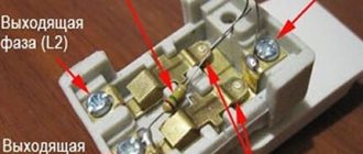
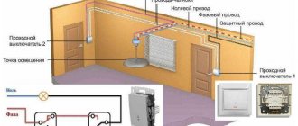
The essence of connecting a lamp through a switch can be visualized on the demonstration stand:
Series and parallel connection formulas
Separate formulas are used to calculate serial and parallel connections.
All calculations are based on Ohm's law and are valid for any electrical circuit
If it is necessary to calculate the resistance value ®, then count one by one: R = R1 + R2 + R3 (the number is not limited, it is important to add up the indicators of all sections).
Note! If the electrical circuit is connected by a mixed type, the values are calculated separately for each section - parallel and serial. The results are then added up and the final value is obtained.
To calculate the voltage drop for different connections, use the following formulas (series and parallel, respectively):
- U = I * Rtotal;
- U = U1 = U2 and so on (the voltage value is equal in all sections).
In this formula, U is the final voltage value, Rtotal is the total resistance of the circuit elements, I is the level of current supplied to the section of the electrical circuit.
The current calculation is calculated as follows (the same correspondence is one after the other and parallel):
- I = I1 = I2 and so on (the level is the same regardless of the connected elements and the area);
- I = I1 + I2 + I3 (the values of all connections are added).
From the above formulas it follows that when connected one after another, the same voltage level is created, and when connected in parallel, the same level of current is created.
Tool for getting the job done
In the process of performing electrical work, a home handyman will need a set of the following installation tools:
- Sharp knife.
- Pliers (pliers).
- Side cutters.
- Slotted screwdrivers, thin and medium, possibly Phillips medium.
Electrical tape may be required to insulate the wire connections inside the junction box or light housing. In these cases, it is recommended to use CB tape. Over time, it does not melt or stick to the constantly heating contacts it insulates, but only dries out. If necessary, crumble well with pliers.
Before you begin the simplest installation, draw a diagram for connecting electrical appliances in a way that will be clear to you, and think over the procedure
It’s great if you have a special wire stripping tool - a stripper or wire cutters with slots for stripping insulation. In the absence of such devices and a large amount of work, you can get by with a folk remedy by modifying the side cutters.
To do this, use a file to make opposite cuts in the cutting edges closer to the hinge, which together should form a hole slightly larger than the diameter of the exposed wire strand.
The simplest scheme
A 220 V LED lamp is one of the types of lighting lamps in which the luminous flux is created by converting electrical energy into luminous flux using an LED crystal. To operate LEDs from a stationary household 220 V network, you need to assemble the simplest circuit shown in the figure below.
The circuit of a 220-volt LED lamp consists of an alternating voltage source of 220–240 V, a rectifier bridge for converting alternating current into direct current, a limiting capacitor C1, a capacitor for smoothing ripples C2 and LEDs connected in series from 1 to 80 pieces.
Principle of operation
When an alternating voltage of 220 V of variable frequency (50 Hz) is supplied to the LED lamp driver, it passes through the current-limiting capacitor C1 to a rectifier bridge assembled from 4 diodes.
After this, at the output of the bridge we receive a constant rectified voltage required for the operation of the LEDs. However, to obtain a continuous light output, it is necessary to add an electrolytic capacitor C2 to the driver to smooth out the ripples that occur when rectifying the alternating voltage.
Looking at the design of a 220-volt LED lamp, we see that there are resistances R1 and R2. Resistor R2 is used to discharge the capacitor to protect against breakdown when the power is turned off, and R1 is used to limit the current supplied to the LED bridge when turned on.
Recommended Cables and Wires
For new installations of home electrical lighting networks, it is recommended to use VVGng cables with single-wire copper, 1.5 sq. mm cross-section, in non-flammable insulation with conductors of different colors:
When installing, it is advisable to maintain a combination of color uniformity and their functional purpose. This requirement will protect and also simplify further maintenance of the electrical wiring.
When making new wiring, wherever provided by the design of electrical appliances, be sure to connect the neutral protective (grounding) conductor and do not use it for other purposes
In houses where the wiring is still made of aluminum, replacement of individual sections of lighting lines embedded under plaster must be done with APPV-1.5 wire having aluminum cores or a similar cable when laid open. The same material is used due to oxidation of the aluminum and copper contacts inside the junction boxes.
If it is possible to replace twists with terminal connections, the use of copper wiring is allowed. It is strongly NOT recommended to use any cables or wires with stranded (soft) cores.
About connecting the ground wire in the chandelier
In modern chandeliers with metal fittings, a yellow-green
colors.
The grounding wire is designated by the Latin letters PE
.
If the apartment's electrical wiring is made with a grounding wire (it should be yellow-green
, but can be of any color), then it also needs to be connected to the terminal to which
the yellow-green
wire of the chandelier is connected.
In old houses, apartment electrical wiring is usually made without a grounding conductor. Old chandeliers or those with plastic fittings also do not have a grounding conductor. In such cases, the grounding conductor is not connected; it will not affect the performance of the chandelier, since it only performs a protective function.
In the photographs, the wires coming out of the ceiling and chandelier are shown in white, and this is no coincidence. There is no single international standard for the color marking of wires in the electrical network, and even more so in chandeliers. And in Russia, the color marking of electrical wires has changed since January 1, 2011. Only the PE ground wire is marked yellow-green in the specifications of all countries
color.
Attention! Before connecting the chandelier, to prevent electric shock, it is necessary to de-energize the electrical wiring. To do this, turn off the corresponding circuit breaker in the distribution panel and check the reliability of the shutdown using the phase indicator.
Application of junction box
Cables and wires do not go directly from the panel to electrical appliances, from switches to light bulbs. All outgoing and incoming lines of electrical equipment are found in specific installation units called branch boxes. There they communicate in a certain way.
Most often, boxes have empty space inside. The wires of different lines are then connected to each other using twists. To ensure reliability, it is recommended to treat the tails of the connections with special welding. Copper conductors can simply be soldered.
Before laying inside, open contacts are insulated from each other with cotton tape. You can screw special insulating clamps onto the twisted wires. Here, insulating tape is no longer needed.
Do not use PVC-type electrical tape to insulate twists - over time it will stick to the contacts so that it will be difficult to remove if necessary.
If the box is equipped with screw terminals, the contacts are then made using them. Such devices allow you to connect aluminum and copper conductors. Clamp terminals can be used, but this is only if there is sufficient space for laying the ends of the wires connected by them.
Removing insulation from wiring
To remove part of the external insulation of the VVGng cable, a knife is required. It should be so sharp that even an inexperienced DIYer can make confident cuts.
The first cut is made from the end along the shell by 3-4 cm. After this, with one hand they grasp the bundle of freed ends of the wires, and with the other they pull the cut shirt. Then she breaks down herself.
The depth of the tear is such that the freed tails of the wires are of the maximum length that the junction box, socket box or lighting fixture housing allows for installation. The reserve will serve you well in the future when loose contacts burn out.
The torn cable jacket is turned inside out and carefully, so as not to damage the insulation of the wires, cut off in a circle.
The easiest way to strip the conductors is, of course, with a tool for removing insulation - a stripper or at least side cutters with slots. In the absence of these, a knife is used in the same way as before. The use of simple side cutters is allowed. As a last resort, use the biting edges of pliers.
Removing a section of the outer sheath from the cable. It is important not to cut the wire insulation, and when stripping the wire insulation, do not damage the metal surface of the wires
With light movements of the tool in a circle, they cut shallowly into the insulation and tighten it. The main thing is not to cut through the metal of the conductor, otherwise where there is damage, it will definitely break off. It would be good if it happened immediately, and not after installation.
The size of the exposed area is determined by the connection method. When these are screw terminals of a box, switch, chandelier or sconce, 0.5-1 cm may be sufficient. For twisting with the wiring of the lamp, 2-3 cm will be required.
If the strands are located in a junction box, the rule is that the bigger the better, especially without soldering or welding. Usually 3-5 cm.
When using screw-on insulating clamps, the clamping terminals are adjusted to the stripping length individually.
How to choose the right one
In order not to miss the choice, it is important to determine the required level of lighting. There are accepted standards established by SanPin. They directly depend on the area of the room and its purpose.
How to choose the right lamp
Important! For a bedroom, 150 lux is required, for a children's room - 200 lux, and the living room will need the same 150 lux of illumination.
After establishing the required brightness, you should calculate the exact number of lamps and light bulbs. Luminous output varies from manufacturer to manufacturer, so wattage is not the only thing you need to pay attention to when purchasing.
It is important to determine the exact number of lighting fixtures
Already at the stage of creating a room design, the idea regarding lighting sources and their installation locations becomes clear. Manufacturers offer a huge range of different lamps - from ceiling and sconces, to wall and floor lamps, so buyers will be able to bring to life even the most daring projects.
If the ceilings of the room are low, it is better to choose a large flat ceiling lamp. It will significantly increase the space and become an important component of the chosen interior.
A flat ceiling lamp will fit well into the interior of a room with low ceilings.
Massive lamps look better against the background of small ones. Small ones look lonely and uncomfortable. At the same time, it is important not to “overload” the space with a voluminous chandelier, which will not look aesthetically pleasing.
The interior of a room with high ceilings will be ideally decorated with a large ceiling chandelier.
Majestic crystal chandeliers are perfect for rooms with high ceilings.
There are several types of lamps.
Hanging
The chandelier is probably the most recognizable design of this type. Thanks to the wide variety of shades, it is capable of producing both directional and diffused light.
Fastening is done to the ceiling using a spring, chain or rod.
You may be interested in: Reasons for blinking light bulbs and their elimination
Pendant lamps are not recommended for installation in rooms with low ceilings. Thanks to the adjustable suspension function, some chandeliers look very advantageous above the dining table.
Successful placement of a tall chandelier above the dining table
Built-in
Often used in combination with suspended or stretch ceilings. The main advantage is its small size. Recessed lamps do not require much space and are not at all inferior in the amount of light to their more massive competitors.
Invoices
A real find for a room with low ceilings. Such lamps have a huge number of variations and are suitable for any interior. Their advantage is compactness.
Flexible
Such lighting devices are most often used as illumination. LED strips look good on the ceiling plinth.
Spots
They are often called soffits. Perfect for those who for some reason are forced to abandon a stretch ceiling with built-in light. The spots are capable of producing rotating, narrowly focused light, creating a cozy atmosphere.
Nuances of twist formation
When twisting two wires, their exposed ends are folded in an “X” shape so that the intersection is at the beginning of the insulation. Then the ends of the veins are pinched with your fingers and twisted as much as possible. Next, the process is helped with pliers.
Three or more wires are connected in the same way. If the connection comes out both long and flexible, fold it in half, pressing it with pliers. A shorter twist requires less electrical tape.
The longer the cleaned tails of the wires are, the easier it will be to make twists, and the more reliable the contact will be - and the excess can always be trimmed
The insulating tape begins to be applied from the factory insulation of the twisted wires to the width of the tape. After passing in one layer until the end of the bare tails, a couple more turns are made, as if wrapping up the air. This “void” is bent back into a twist - a protected end is obtained, and the second row is wound up with the obligatory approach to the main insulation of the cores.
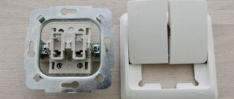
Correct installation of the switch
By design, switches are available for indoor and outdoor installation. Modern outdoor switches are suitable for mounting on any surface without additional insulating supports. Internal switches are hidden in round sockets in the wall, equipped with special cups called socket boxes.
Socket boxes are a standard electrical installation unit. They are also used to equip sockets, which is why they are called that. "Subswitches" wouldn't sound very good.
The correct location of the switch is considered to be one in which turning on occurs by pressing the upper part of the key, and turning off occurs by pressing the lower part. This gives even a short person the opportunity to react in an emergency situation and quickly turn off the power to an electrical device by hitting the key from top to bottom with his fingers.
Place switches on the walls so that you don’t have to “search for them by fumbling in the dark,” and all family members can easily use them
With proper connection, a phase wire comes to the switch from the junction box. Interrupting the phase wire circuit so that when the lamp is turned off there is no voltage - the main task of the switch.
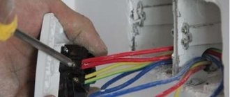
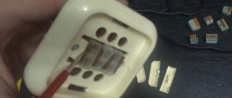
The following photo selection illustrates the connection process clearly:
If the design of the device allows, inside the switch itself, the phase wire is connected to the upper terminals, and all outgoing conductors are connected to the lower contacts. This rule applies to the arrangement of any electrical installation.
Due to design features, exceptions to the general rules are pass-through and crossover switches, which are discussed below.
Neutral or phase on the switch?
At first glance, the connection diagram for a chandelier when there is a zero break is the same as when installing a switch in a phase. However, in the first case, the lamp is always energized. Therefore, there is a possibility that a person will get an electric shock while performing work. This can happen when replacing a burnt-out lamp or while connecting a lighting fixture. In addition, if the insulation or electrical connections inside the chandelier are damaged, there is a possibility that the conductor will short out to the housing. In this case, during contact with the lamp, a person will feel a strong electrical discharge. Its consequences can even be fatal under certain conditions. Therefore, we advise you to check in advance which wire the switch breaks and if it is zero, then change it to a phase in the junction box.
Types of household switches
There are a wide variety of switches used in modern home interiors. One of the popular articles posted on our website introduces in detail the classification of light control devices.
When choosing a home switch, pay more attention not to its design, but to functionality, strength of fastenings and reliability of electrical contacts
Based on the differences in their functionality, the following most common varieties are distinguished:
A motion sensor switch turns on the lamp automatically, reacting to a person passing by.
Laws of mixed compounds
The mixed inclusion of illuminators is described as follows:
- It is based on the parallel connection of several electrical branches.
- In some of the branches, the loads are switched on in series in the form of a row of light bulbs located one after the other.
It is possible to connect various types of consumers to separate parallel branches, including incandescent lamps, as well as halogen or LED sources.
When considering the characteristics of a mixed compound, the following patterns must be taken into account:
- The same current flows through each of the series-connected sections of the circuit.
- When passing through a link with parallel-connected consumers, it branches out, and at the output it again becomes single-line.
- As the number of elements in the operating circuit increases, the absolute value of the current in it decreases.
- The voltage on one link is equal to the product of the current component and the total resistance of the branch (Ohm's law).
- As the number of elements in the circuit increases, the voltage on each of them decreases accordingly.
It is recommended, when using a mixed circuit, to group lamps of the same power into serial circuits, and to place illuminators with different energy consumption in parallel branches.
Types of lamps for home use
Tube progress keeps pace with switches. Their diversity is also impressive.
When purchasing an energy-saving light bulb, you should focus on well-known brands - after all, it should not only be efficient, but also last as long as possible
But here, too, some more popular types are defined:
Energy-saving fluorescent light bulbs are increasingly replacing the usual ones. The operating principle is similar to fluorescent lamps. They are screwed in like incandescent lamps (hereinafter simply “energy-saving lamps”).
Schemes of serial and parallel connections of light bulbs
For parallel and serial connections of light bulbs, special circuits are used. To make it easier to understand, similar images of elements are used. For example, inputs and outputs are indicated by a vertical bar and a "+" or "-". Electrical elements (light bulbs, lamps) - a crossed out circle, resistors - an empty rectangle.
Symbolic images on electrical diagrams are of the same type, so it is more familiar and convenient to read the order in which the elements are connected
Connecting a light bulb is one of the easiest tasks for an electrician. Another question is organizing a common circuit in a living room or assembling a chandelier with several incandescent lamps. To avoid difficulties during operation, to prevent breakdowns as much as possible and to simplify future network repairs, it is necessary to familiarize yourself in advance with possible connection diagrams and take into account their advantages and disadvantages.
Ways to power a light bulb through a switch
Perhaps some of the schemes under consideration for the mutual connection of a household switch to a wall or ceiling light bulb will omit the details of supplying the neutral protective (grounding) wire. It seems that connecting it will not cause any difficulties.
In a standard electrical cable, this is a core with yellow insulation and a green stripe along it. The place where it is connected to the electrical appliance is indicated by a sign
.
#1: The simplest connection of the lamp
The most basic thing is to connect the “on/off” lighting device to a single-key switch with two wires. Most of all it is suitable for a single single-lamp lamp.
When developing new switches, manufacturers adhere to standards - replacing a conventional “one-key switch” with an electronic device will be without problems
When the old wiring has only two wires coming out of the ceiling or wall feeding the light electrical device, and the alteration is complicated, you can connect a lamp with more lamps. But with this connection, all the light bulbs of the lighting device will turn on simultaneously.
A classic single-key switch without upgrading the wiring can be easily replaced with a light dimmer switch (dimmer) made in a single unit. It is possible to purchase a device with a regulator like a key, or you can purchase it in the form of a round knob.
The characteristics of the dimmer must correspond to the power of the connected lamp. The only thing is that it cannot be used in conjunction with lighting fixtures equipped with energy-saving, LED or fluorescent lamps.
For standard installation in ordinary socket boxes, the industry has mastered the production of touch switches that have only “on/off” functions. They are also connected with two wires and can replace simple single-key ones.
#2: Separate switching on of chandelier lamps
Typically, three- and five-arm chandeliers are designed so that the lamps can be connected separately or together in groups (1+2/2+1; 2+3/3+2). This allows you to regulate the illumination of the space by the number of simultaneously working light bulbs.
If possible, it is better to attach the grounding wire to the chandelier directly, rather than through the terminal block - this will increase the safety of the lamp
In this case, you will need a two-key switch and an electrical wiring with at least three wires. By turning on one of the two or both keys at once, the brightness of the lighting fixture will be adjusted.
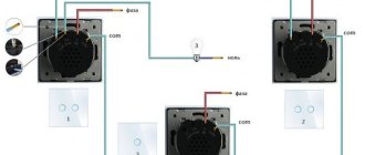
Another switch with two keys is used to control from one point the lighting of two, most often adjacent, rooms independently, for example, a toilet and a bathroom, a hallway and a storage room.
If, instead of the usual two-key switch, you use a two- or even three-key switch for a chandelier with separate controls built into the keys, then all its lamps will light at the same time, and their intensity can be controlled in stages by switching the keys.
#3: Controlling a five-arm chandelier
Where separate and simultaneous control of three independent lighting devices is necessary, a three-key switch is installed.
When connecting the switch to the circuit, make sure that it is the phase wire that comes from the box - always try to place it on the top terminal
To surprise guests, you can connect a five-arm chandelier via a switch with three keys. True, a small alteration will be required on the terminals of the lamp itself. From a group of three linear wiring, one needs to be disconnected and used independently.
Then, using various combinations of pressing the keys of a three-key switch, it will be possible to turn on from one to five lamps at a time (1+2+2/2+2+1/2+1+2).
#4: Lamp – one, switches – two
What to do when the corridor is long and dark? This situation can be resolved by installing a lamp with two pass-through single switches at different ends of the passage. The inconvenience of this method is the indefinite position of the “on/off” keys.
This lighting control technique is also applicable when moving up the stairs, in an attached garage (entrance from the house, exit through the gate and vice versa). An additional switch near the sleeping area will not be superfluous if the room is long enough.
When using non-standard lamp connection diagrams in practice, you should make sure of their feasibility, as this increases the length of the wires and the complexity of installation (+)
Is it possible to illuminate flights of stairs independently of each other, going up or down the steps? Additionally, you will need a single pass-through switch on the interfloor platform. By pressing just one key, it will simultaneously turn on the next lamp and turn off the previous one.
#5: Turning on a light bulb from different places
To control the luminaire from more than two centers, crossover single switches will be required in addition to the pass-through ones. Each new point - one at a time.
A lot of switches are convenient if living rooms open into a spacious hall at home. The occupants of any room will be able to independently turn on the lights at their doors and turn them off in all other places equipped with auxiliary switches.
With proper organization of installation locations for additional switches, in addition to ease of use of lighting, significant energy savings can be achieved
This method is also appropriate in rooms with a hotel-type layout - many doors opening into a long corridor.
#6: Connecting a chandelier with a fan
It is inconvenient to pull the pendant on a chandelier equipped with a fan to turn it on. This is also problematic when the ceiling is high.
It is easier to use the studied methods of separately connecting chandelier lamps. The fan is connected through one of the keys of a two- or three-key switch.
In the first option, the lamp can only burn completely. In the second, the light bulbs will light up in two groups.
#7: Built-in motion sensors
The motion sensor itself is already a switch device. But we are interested in it precisely when it has a standard case and can be mounted in a socket box.
It turns out that it is connected to the gap in the phase conductor going to the lamp like a regular switch. But the problem is that the internal electronic circuit of such a device requires a full 220V power supply, which means one more wire, blue, zero.
In accordance with the principles of connecting the lamp, motion sensors (1) are connected through the switch. If there is a need for periodic constant operation of the lamp, a switch (2) is included in the circuit. If one sensor cannot cover a large room, then several are connected to the lamp. In this case, it is the sensors that play the role of a switch (3)
If you want to install a switch with a built-in motion sensor instead of a single-key one, you cannot do without replacing the two-wire wire stretching to it from the junction box with a three-wire one.
Manufacturers do not mark time in one place. They come up with all the new, more ingenious lighting devices. But no matter how cosmic the lamp may seem, there is always a simple way to connect it. Basic diagrams, rules for connecting light bulbs with switches, conditions for safe electrical work will remain standard for a long time.
What is a serial connection
A serial connection is often installed to systematize luminaires and several consumers. The basic principle is to solder the parts one by one, sequentially, without interlacing. That is, the output of the first contact is connected to the input of the next one, the rest are soldered in exactly the same way.
Connecting a light bulb is the first thing an electrician should know how to do.
Note! A special feature of this connection technique is that all connected devices are powered by a single cable from one initial point (for example, a distribution box).
Differences between serial connection and other connection schemes:
- the current level is the same on all elements and sections of the connection;
- the final voltage value is calculated as the sum of the indicators in each of the available sections;
- the maximum resistance is equal to the sum of the resistances of each cable.
Such a connection is rarely used in its pure form, more often as an element of a mixed connection.
The level of total resistance and voltage is always higher than on individual elements (in sections). The indicated patterns are valid for any network with sequential connection, regardless of the number of connected parts.
Important! The disadvantage of the connection is that if one of the units fails, the power to the entire system will be cut off. On the other hand, it is easier to find out the area where the failure occurred.