It has become the norm for all of us that in the distribution boards of residential buildings, it is mandatory to install incoming circuit breakers, modular circuit breakers for outgoing circuits, RCDs or differential circuit breakers in rooms and equipment where possible current leaks are critical (bathrooms, hob, washing machine, boiler ).
In addition to these mandatory switching devices, almost no one needs to explain why a voltage control relay is needed.
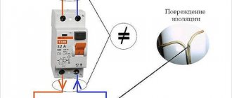
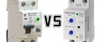
SPD or voltage relay
Everyone started installing them everywhere. Roughly speaking, it protects you from 380V instead of 220V going into the house. At the same time, you don’t need to think that increased voltage gets into the wiring due to an unscrupulous electrician.
Natural phenomena that do not depend on the qualifications of electricians are quite possible. A tree simply fell and broke the neutral wire.
Also, do not forget that any overhead line becomes obsolete. And even the fact that a new line has been connected to your house using a self-supporting insulated insulation system, and everything in your house is installed according to the rules, does not guarantee that everything is fine at the supply transformer substation itself - the transformer substation.
There, the zero on the busbar may also oxidize or the contact on the transformer pin may burn out. No one is immune from this.
That is why all new electrical panels are no longer assembled without UZM or RN of various modifications.
As for surge voltage protection devices, or SPDs for short, most here have doubts about the need to purchase them. Are they really that necessary, and is it possible to do without them?
Such devices appeared quite a long time ago, but still no one is in a hurry to install them en masse. Few ordinary consumers understand why they are needed at all.
The first question that arises in their minds is: “I installed a surge voltage relay, why do I need another SPD?”
Remember that the SPD primarily protects against impulses caused by thunderstorms. Here we are not talking about a banal increase in voltage to 380V, but about an instantaneous impulse of several kilovolts!
No voltage relay will save you from this, but will most likely burn out along with all other equipment. At the same time, the SPD does not protect against small differences of tens of volts or even hundreds.
For example, devices for installation in home panels, assembled on varistors, can only operate when the change reaches values above 430 volts.
Therefore, both LV and SPD devices complement each other.
Classification
Surge protection devices differ in functionality, which is determined by the model class. There are three types of SPDs in total:
1 class
In this category, devices that are the first to take the blow in the event of a direct lightning strike on a building, mast or power line. They are used in switchboard input switchgears, at facilities located in open areas with lightning rods installed nearby. SPDs of class 1 are designed to operate with pulsed discharges, the current strength of which can reach 30-60 kA. For example, SPD OPS-10V-1R-R class 1.
2nd grade
Designed to directly protect consumer networks from residual effects of lightning or communication overvoltages. As a rule, they are installed in switchboards at the entrance to apartments. Since these protection devices belong to the “second line of defense”, the nominal value of the discharge current for which they are designed is lower than that of class 1 and ranges from 20 to 40 kA. An example of such devices is SPD OPS-10S-1R Class 2.
3rd grade
SPDs used to prevent the impact of surge voltage directly on the equipment used. Depending on the design, they can be connected directly to an outlet or a separate group when distributing electrical wiring. The presented protection devices are designed to operate with pulse currents in the range of 5-10 kA. For example, SPD OPS-10D-2R class 3.
It is worth paying attention to the following: all presented SPDs can be installed either partially or completely at one site. However, everything depends on the configuration of the existing power supply circuit.
Protecting your home from thunderstorms
A thunderstorm is a spontaneous phenomenon and it is still not very easy to calculate it. In this case, lightning does not have to hit the power line directly. It is enough to hit next to her.
Even such a lightning discharge causes an increase in the voltage in the network to several kilovolts. In addition to equipment failure, this is also fraught with the development of a fire.
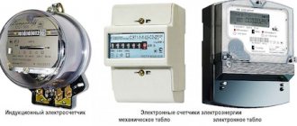
Even when lightning strikes relatively far from overhead lines, pulse surges occur in the networks, which damage the electronic components of home appliances. A modern electronic meter with its filling may also suffer from this impulse.
The total length of wires and cables in a private house or cottage reaches several kilometers.
This includes both power circuits and low current:
- Internet
- TV
- CCTV
- security alarm
All these wires take on the consequences of a lightning strike. That is, all your kilometers of wiring receive a gigantic interference, from which no voltage relay can save you.
The only thing that will help and protect all the equipment, costing several hundred thousand, is a small box called an SPD.
They are installed mainly in cottages, and not in high-rise apartments, where the supply to the house is made with an underground cable. However, do not forget that if your transformer substation is not powered by a 6-10 kV cable line, but by an overhead overhead line or overhead line (SIP-3), then the effect of a thunderstorm on medium voltage can also be reflected on the 0.4 kV side.
Therefore, do not be surprised when, during a thunderstorm in your high-rise building, many neighbors’ WiFi routers, cordless phones, televisions and other electronic equipment simultaneously fail.
Lightning can strike a power line several kilometers from your home, but the impulse will still arrive at your outlet. Therefore, despite their cost, all electricity consumers should think about purchasing an SPD.
The price of high-quality models from Schneider Electric or ABB is approximately 2-5% of the total cost of rough electrics and an average switchboard. In total, this is not such a huge amount of money.
Main types
The type of network interference includes both overvoltage associated with a phase imbalance of a longer duration, and overvoltage caused by a lightning discharge.
Important! When a pulse overvoltage occurs, this indicates the occurrence of a short-term high voltage between phases or phase and ground with a duration, usually up to 1 ms.
A lightning discharge is a powerful impulse overvoltage. It occurs when lightning strikes an electrical system. If the distance from a lightning strike reaches up to 1 km, then such a pulse overvoltage can cause failure of electrical equipment. A direct impact produces an instantaneous pulse current of up to 100 kA/s. Typically, the discharge duration is up to 1 mS.
What types of voltage limiter are divided into?
If there is a lightning rod system, the discharge pulse can be evenly distributed between the lightning rod, power supply, communication line, and household communications. This process depends on the design of the structure itself, the communication system, and the laying of the line.
Switching in the power grid causes pulsed power overvoltage. For example, if you disconnect an isolation transformer that has a power of 1 kVA 220/220 V from the network, then all the energy is released into the load in the form of a high-voltage pulse with a voltage of up to 2 kV.
The power of any transformer in the power grid is much greater, and accordingly, the emissions will be more powerful. In addition, switching occurs against the background of an arc, which becomes a source of radio frequency interference.
Note! The electrostatic charge that accumulates during the operation of technological equipment, although it has little energy, is discharged at an unpredictable moment.
The amplitude and type of overvoltage pulse vary not so much from the source of interference, but from the parameters of the network itself. No two cases of surge overvoltage are the same, but for the production and testing of protection devices there is a standard for the parameters of current, shape and voltage, overvoltage in different cases.
For example, for the expected current from a lightning discharge, a current pulse of 10/350 μs is taken, and for the indirect effects of lightning and various switching overvoltages, a current pulse with characteristics of 8/20 μs is taken. When comparing two devices with a high pulse discharge current of 20 kA at 10/350 μs and 20 kA at a pulse of 8/20 μs, the real power of the first will be 20 times greater.
Switching protective devices
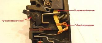
Such limiters have other names, for example, spark gap. The operating principle of this device is based on the use of the spark gap phenomenon. The design has an air gap in the jumper, which serves to connect power lines to the ground loop. The circuit in the jumper is open at rated voltage.
Switching protective devices are also called spark gaps
If a lightning discharge occurs due to overvoltage in the power line, an air gap breakdown will occur, the circuit between the phase and the ground will be closed, and the high voltage pulse will be directly grounded. The design of the valve arrester in a circuit with a spark gap is like a resistor on which high voltage pulses are suppressed. As a rule, arresters are used in high-voltage networks.
Limiters (SPD)
Thanks to new devices, it was possible to replace the more outdated huge models. To determine the performance of the limiter, you should carefully familiarize yourself with the characteristics of the nonlinear resistor, since the arrester operates on the basis of the current-voltage function.
In the production of varistors, zinc oxide material is usually used. The formation of the component occurs due to the combination of the solution with other substances. The result is a pn junction with current-voltage characteristics. If the voltage in the network corresponds to the nominal parameters, then the current in the varistor circuit is zero. When an overvoltage occurs in a pn junction, the current conductivity increases. Because of this, the voltage value drops to the nominal value.
You might be interested in Grounding an electrical panel
Characteristics of the network surge suppressor
Note! After standardizing the network parameters, the varistor returns to non-conducting mode without affecting the operation of the device.
Combined
Combined devices operate under normal operating conditions with unfavorable voltages from 0.94 to 1.96 values. These models are equipped with a resistor. In action, the combined device not only grounds the voltage, but also simultaneously stabilizes the value in the structure itself.
Combined surge arrester
Classes
Such devices are divided into several categories:
- I prevents direct exposure to lightning strikes. As a rule, such devices have input distribution equipment (ADS). It is usually used for administrative and industrial buildings and residential apartment buildings;
- II helps to protect the distribution network from overvoltages that may be caused by switching or secondary protection functions. This is done to prevent exposure to a strong lightning strike. As a rule, they are installed and connected directly to the network in the panel;
- III carefully protects equipment from voltage surges that may result from residual surges and asymmetrical voltage distribution between phase and neutral lines. The operating principle of such a device is to operate in high-frequency interference filter mode. They are connected and installed in private houses or apartments. Particularly popular is the product made in the form of a module. This device can be easily installed on a DIN rail.
What classes are SPDs divided into?
SPD classes
Today, all surge voltage devices are divided into three classes. And each of them plays its role.
The first class module dampens the main impulse; it is installed on the main input panel.
After the largest overvoltage has been extinguished, the residual impulse is taken over by a class 2 SPD. It is mounted in the distribution panel of the house.
If you do not have a Class I device, there is a high probability that the entire impact will be taken by the II module. And this could end very sadly for him.
Therefore, some electricians even discourage customers from installing impulse protection. Motivating this is that since you cannot provide the first level, then you should not spend money on it at all. There will be no point.
However, let's see what not a familiar electrician says about this, but the leading company for lightning protection systems, Citel:
That is, the text directly states that class II is mounted either after class 1, or AS AN INDEPENDENT DEVICE .
The third module directly protects a specific consumer.
If you do not want to build all this three-stage protection, purchase SPDs that are initially designed to work in three zones 1+2+3 or 2+3.
Such models are also produced. And they will be the most universal solution for use in private homes. However, their cost will certainly scare off many.
How to determine the type of grounding system
To determine the type of grounding system, you need to consider the PEN conductors, that is, how they are separated. If everything is ready, the wiring is similar to the TN-CS system. In this case, for a three-phase circuit, five main wires come from the main distribution panel of the house, but for a single-phase circuit, only three wires are used. PEN conductors are divided into two components: PE and N.
Note! If it is not split, the wiring will work according to the TN-C system, with 4 wires from the three-phase system and 2 wires from the single-phase system coming from the distribution panel.
Based on the principles described, the type of grounding system can be easily determined. In all cases when the TN-C system is used in private homes, it is recommended to transfer it to the TN-CS scheme, which is more promising and safer.
You may be interested in this Features of a single-phase electric meter
How to calculate a grounding system
Electrical panel diagram with SPD
The circuit diagram of a distribution board that is well-equipped from the point of view of protection against all voltage surges and surges should look something like this.
At the input in front of the meter there is an input circuit breaker that protects the metering device and the circuits inside the panel itself. Next is the counter.
Between the meter and the input machine there is an SPD with its own protection. The electricity supply organization can, of course, prohibit such installation. But you can justify this by the need for surge protection for the meter itself.
In this case, it will be necessary to mount the entire circuit with the devices in a separate box under a seal in order to prevent free access to exposed live parts up to the meter.
However, here the issue of replacing the triggered module and breaking the seals will arise. Therefore, agree on all these points in advance.
After the metering device there are:
- voltage relay UZM-51 or equivalent
- RCD 100-300mA – fire protection
- RCDs or differential circuit breakers 10-30mA - protecting people from leakage currents
- simple modular machines
If there are no questions with the usual components when assembling such a shield, then what should you pay attention to when choosing an SPD?
For operating temperature. Most electronic types are designed to operate at ambient temperatures down to -25C. Therefore, it is not recommended to install them in street shields.
The second important point is the connection diagrams. Manufacturers may produce different models to suit different grounding systems.
For example, it will no longer be possible to use the same SPDs for TN-C or TT and TN-S systems. You will not achieve correct operation from such devices.
Connection diagrams
Here are the basic SPD connection diagrams depending on the design of the grounding systems using the example of models from Schneider Electric. Connection diagram for a single-phase SPD in a TT or TN-S system:
The most important thing here is not to confuse the connection location of the N-PE insert cartridge. If you plug it into a phase, you will create a short circuit.
Diagram of a three-phase SPD in a TT or TN-S system:
Connection diagram for a 3-phase device in the TN-C system:
What should you pay attention to? In addition to the correct connection of the neutral and phase conductors, the length of these same wires plays an important role.
From the connection point in the device terminal to the grounding busbar, the total length of the conductors should be no more than 50cm!
And here are similar diagrams for surge protectors from ABB OVR. Single-phase option:
Three-phase circuit:
Let's go through some of the schemes separately. In the TN-C circuit, where we have combined protective and neutral conductors, the most common protection solution is to install an SPD between the phase and the ground.
Each phase is connected through an independent device and operates independently of the others.
In the TN-S network version, where the neutral and protective conductors have already been separated, the circuit is similar, but here an additional module is mounted between zero and ground. In fact, the entire brunt of the blow falls on him.
That is why, when selecting and connecting the N-PE SPD option, individual characteristics for the pulse current are indicated. And they are usually greater than the phase values. In addition, do not forget that thunderstorm protection is not only a properly selected surge protector. This is a whole complex of events.
They can be used both with and without lightning protection on the roof of the house.
Particular attention should be paid to a high-quality grounding loop. One corner or pin driven into the ground to a depth of 2 meters will clearly not be enough here. A good ground resistance should be 4 ohms.
Operating principle
The operating principle of the SPD is based on attenuating the voltage surge to a value that the devices connected to the network can withstand. In other words, this device, even at the entrance to the house, dumps excess voltage onto the ground loop, thereby saving expensive equipment from a destructive impulse.
Determining the status of the protection device is quite simple:
- green indicator – module working
- red – module needs to be replaced
However, do not enable the module with the red flag. If there is no spare one, then it is better to dismantle it altogether.
An SPD is not always a disposable device, as some people think. In some cases, class 2 and 3 models can fire up to 20 times!
Operating principle of the device
The operating principle of the protective device is quite simple. Typically, a surge protector can eliminate an overvoltage instantly. This is a simple voltage tapping circuit. For example, if the voltage is normal, then the resistance of the varistor will be determined by megaohms. If an overvoltage appears on the line, then the varistor moves to the cable category. An electric current passes through the conductor and flows to ground.
How does a voltage limiter work?
For your information! The operating principle of SPDs is classified into two categories: valve/spark arresters. They are usually used for high voltage networks, like protective devices with varistors.
When the action of a lightning discharge during overvoltage is detected in the arresters, then this can break through the air passage in the jumper that connects the phases to the ground loop. A high voltage pulse hits the ground. In the case of valve-type arresters, the reduction of the high-voltage pulse in the circuit with the spark gap occurs through a resistor.
SPDs in gas-filled arresters are suitable for buildings where an external lightning protection system or electricity supply occurs through the air due to special lines.
Equipment with a varistor is connected in parallel with the protected device. In the absence of pulse voltage, the current flowing through the varistor is almost zero. However, when an overvoltage occurs, the resistance of the equipment drops sharply, it allows current to pass, dissipating the absorbed energy, causing the voltage to drop to its nominal value. Thus the varistor returns to non-conducting mode.
The SPD has built-in thermal protection, which prevents burnout at the end of its service life. However, over time, the device breaks down and the voltage limiter needs to be replaced. The indicator itself informs about problems.
You might be interested in How RCD works and what it is
Circuit breakers or fuses in front of the SPD
To maintain uninterrupted power supply in the house, it is also necessary to install a circuit breaker that will turn off the surge protector. The installation of this machine is also due to the fact that at the moment the pulse is removed, a so-called accompanying current arises.
It does not always allow the varistor module to return to the closed position. In fact, it does not recover after being triggered, as in theory it should.
As a result, the arc inside the device is maintained and leads to a short circuit and destruction. Including the device itself.
In the event of such a breakdown, the machine is triggered and de-energizes the protective module. Uninterrupted power supply to the house continues.
Remember that this machine does not primarily protect the arrester, but your network.
At the same time, many experts recommend installing not even a machine, but modular fuses as such protection.
This is explained by the fact that the machine itself during a breakdown is exposed to a pulsed current. And its electromagnetic releases will also be under increased voltage.
This can lead to breakdown of the trip coil, burning of contacts and even failure of the entire protection. In fact, you will find yourself unarmed in the face of a short circuit.
Therefore, installing an SPD after a machine is much worse than after fuses.
There are, of course, special automatic switches without inductors, which have only thermal releases in their design. For example Tmax XT or Formula A.
However, considering this option for cottages is not entirely rational. It is much easier to find and buy modular fuses. In this case, you can choose the GG type.
They are capable of protecting over the entire range of overcurrents relative to the rated ones. That is, if the current has increased slightly, GG will still turn it off at a given time interval.
There is, of course, a minus to the circuit with a machine or PC directly in front of the SPD. We all know that thunderstorms and lightning are long-term, not one-time phenomena. And all subsequent impacts may be unsafe for your home.
The protection had already worked the first time and the machine gun was knocked out. And you won’t even guess about it, because your power supply was not interrupted.
Therefore, some people prefer to install an SPD immediately after the input circuit breaker. So that when triggered, the voltage in the entire house is turned off.
However, there are pitfalls and rules here too. The protective circuit breaker cannot be of any rating, but is selected according to the brand of the SPD used. Here is a table of recommendations for choosing circuit breakers mounted in front of surge protection devices:
If you think that the lower the nominal value of the machine is installed, the more reliable the protection will be, you are mistaken. The pulse current and voltage surge can be of such magnitude that they will lead to the circuit breaker tripping even before the SPD operates.
And accordingly, you will again be left without protection. Therefore, choose all protective equipment wisely and according to the rules. SPD is a quiet, but very timely protection against dangerous electricity, which comes into operation instantly.
SPD - surge protection device
To bookmarks
Purpose of SPD
Surge protection device (SPD) is a device designed to protect the electrical network and electrical equipment from overvoltages that can be caused by direct or indirect lightning effects, as well as transient processes in the electrical network itself.
In other words, SPDs perform the following functions :
— Protection against lightning strikes of the electrical network and equipment, i.e. protection against overvoltage caused by direct or indirect lightning effects
— Protection against surge voltages caused by switching transients in the network associated with turning on or off electrical equipment with a large inductive load, such as power or welding transformers, powerful electric motors, etc.
— Protection against remote short circuit (i.e. against overvoltage resulting from an existing short circuit)
[Advertising] The Priborenergo company produces high-quality surge protectors with an emphasis on reliability.
SPDs have different names: network surge suppressor - OPS (OSN) , surge voltage limiter - OIN , but they all have the same functions and operating principle.
[Advertising] You can buy surge protectors of high reliability and quality on the website etirussia.ru
Appearance of the SPD:
Operating principle and protection device of SPD
The operating principle of the SPD is based on the use of nonlinear elements, which, as a rule, are varistors.
A varistor is a semiconductor resistor whose resistance has a nonlinear dependence on the applied voltage.
Below is a graph of the dependence of the varistor resistance on the voltage applied to it:
The graph shows that when the voltage increases above a certain value, the resistance of the varistor decreases sharply.
Let's look at how this works in practice using the following diagram as an example:
The diagram shows a simplified representation of a single-phase electrical circuit, in which a load in the form of a light bulb is connected through a circuit breaker, an SPD is also included in the circuit, on one side it is connected to the phase wire after the circuit breaker, on the other - to ground.
In normal operating mode, the circuit voltage is 220 Volts, at this voltage the SPD varistor has a high resistance measured in thousands of MegaOhms, such a high resistance of the varistor prevents the flow of current through the SPD.
What happens when a high voltage pulse occurs in a circuit, for example, as a result of a lightning strike (thunderstorm).
The diagram shows that when a pulse occurs in the circuit, the voltage increases sharply, which in turn causes an instantaneous, multiple decrease in the resistance of the SPD (the resistance of the varistor of the SPD tends to zero), the decrease in resistance leads to the fact that the SPD begins to conduct electrical current, short-circuiting the electrical circuit by land, i.e. creating a short circuit that causes the circuit breaker to trip and shut down the circuit. Thus, the surge suppressor protects electrical equipment from the flow of a high voltage pulse through it.
SPD classification
According to GOST R 51992-2011, developed on the basis of the international standard IEC 61643-1-2005, there are the following classes of SPDs:
SPD class 1 - (also designated as class B ) are used for protection against direct lightning effects (lightning strike into the system), atmospheric and switching overvoltages. They are installed at the entrance to the building in the input distribution device (IDU) or the main distribution board (MSB). Must be installed for free-standing buildings in open areas, buildings connected to an overhead line, as well as buildings with a lightning rod or located next to tall trees, i.e. buildings with a high risk of being directly or indirectly affected by lightning. Normalized pulse with a waveform of 10/350 μs. The rated discharge current is 30-60 kA.
SPD class 2 - (also designated as class C ) are used to protect the network from residual atmospheric and switching overvoltages passing through a class 1 SPD. They are installed in local distribution panels, for example in the input panel of an apartment or office. They are normalized by pulse current with a waveform of 8/20 μs. The rated discharge current is 20-40 kA.
SPD class 3 - (also designated as class D ) are used to protect electronic equipment from residual atmospheric and switching overvoltages, as well as high-frequency interference passing through a class 2 SPD. They are installed in branch boxes, sockets, or built directly into the equipment itself. An example of the use of SPDs of the 3rd class are network filters used to connect personal computers. They are normalized by pulse current with a waveform of 8/20 µs. The rated discharge current is 5-10 kA.
SPD marking - characteristics
SPD characteristics:
- Rated and maximum voltage - the maximum operating voltage of the network for operation under which the SPD is designed.
- Current frequency - operating frequency of the network current for the operation at which the SPD is designed.
- Rated discharge current (the current waveform is indicated in parentheses) is a current pulse with a waveform of 8/20 microseconds in kiloamperes (kA), which the SPD is capable of transmitting many times.
- The maximum discharge current (the current waveform is indicated in parentheses) is the maximum current pulse with a waveform of 8/20 microseconds in kiloamperes (kA) that the SPD is capable of transmitting once without breaking down.
- Protection voltage level is the maximum value of the voltage drop in kiloVolts (kV) across the SPD when a current pulse flows through it. This parameter characterizes the ability of the SPD to limit overvoltage.
SPD connection diagram
A general condition when connecting an SPD is the presence of a fuse or circuit breaker corresponding to the network load on the supply network side, therefore all the diagrams presented below will include circuit breakers (see the SPD connection diagram in the electrical panel here):
Schemes for connecting SPDs (OPS, OIN) to a single-phase 220V network (two-wire and three-wire):
Schemes for connecting SPDs (OPS, OIN) to a three-phase 3800V network
Schematic diagrams for connecting an SPD are as follows:
When installing multi-stage overvoltage protection , i.e. installation of 1st class SPDs in the building's ASU together with 2nd class SPDs in the distribution boards of the building and with 3rd class SPDs, for example, in sockets, it is necessary to maintain a distance between the SPDs along the cable of at least 10 meters:
Was this article useful to you? Or maybe you still have questions ? Write in the comments!
Didn’t find an article on the website on a topic that interests you regarding electrical engineering? Write to us here. We will definitely answer you.
↑ Up
10
https://elektroshkola.ru/apparaty-zashhity/uzip/