Do-it-yourself inverter welding is very simple
Inverter welding is a modern device that is widely popular due to the light weight of the device and its dimensions. The inverter mechanism is based on the use of field-effect transistors and power switches. To become the owner of a welding machine, you can visit any tool store and acquire such a useful thing. But there is a much more economical way, which is due to the creation of inverter welding with your own hands. It is the second method that we will pay attention to in this material and consider how to do welding at home, what is needed for this and what the diagrams look like.
Technological process of argon welding
The main difference between the argon welding process and MMA is the absence of mandatory forming movements and the use of a minimum arc size (only 2 mm). The burner moves slowly and smoothly along one line. This ensures constant flow of argon at the joint, prevents oxidation of the metal, and the welding seam is very thin.
The second most important thing is the need to connect an oscillator. It is needed to ignite an electric arc when using a tungsten electrode. In addition, you need to light it on a coal plate and extinguish it away from the parts being welded.
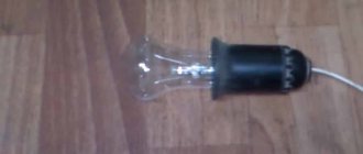
Oscillator for welding
Oscillator circuit
In MMA welding, the arc is ignited by touch. The tungsten in this method can burn, melt the metal, catch a sticky piece, or damage the electrode in other ways. To avoid trouble, you need a special unit that generates high-frequency current for pulsed ignition. It not only gives the initial discharge, but also supports it with stabilizing impulses. This allows the welder to work equally easily with direct and alternating current.
You can buy the device in a store (UVK7) or assemble it yourself using one of the many diagrams provided on the Internet.
Examples of schemes:
Based on UC3842-5 flyback circuit and TV transformer.
Based on NE555 timer.
Do-it-yourself production requires a certain skill in creating printed circuit boards, parts and time, so it is often easier to buy a ready-made one. It is already assembled, configured and often more reliable than self-assemblies.
Another advantage of the factory device is the connection to almost any welding machine through the welding cable attachment. It does not affect the device, it works in parallel only with the arc. When purchasing, you need to take into account the open circuit voltage; if it is higher than planned for argon welding, then the oscillator will not work.
Features of the inverter operation
An inverter-type welding machine is nothing more than a power supply, the one that is now used in modern computers. What is the operation of the inverter based on? The following picture of electrical energy conversion is observed in the inverter:
1) The voltage consumed from the network is converted to DC.
2) Current with a constant sinusoid is converted into alternating current with a high frequency.
3) The voltage value decreases.
4) The current is rectified while maintaining the required frequency.
A list of such electrical circuit transformations is necessary in order to be able to reduce the weight of the device and its overall dimensions. After all, as you know, old welding machines, the principle of which is based on reducing the voltage and increasing the current on the secondary winding of the transformer. As a result, due to the high current value, the possibility of arc welding of metals is observed. In order for the current to increase and the voltage to decrease, the number of turns on the secondary winding decreases, but the cross-section of the conductor increases. As a result, you can notice that a transformer-type welding machine not only has significant dimensions, but also a decent weight.
To solve the problem, an option was proposed for implementing a welding machine using an inverter circuit. The principle of the inverter is based on increasing the frequency of the current to 60 or even 80 kHz, thereby reducing the weight and dimensions of the device itself. All that was required to implement an inverter welding machine was to increase the frequency thousands of times, which became possible thanks to the use of field-effect transistors.
Transistors provide communication with each other at a frequency of about 60-80 kHz. The transistor power supply circuit receives a constant current value, which is ensured by the use of a rectifier. A diode bridge is used as a rectifier, and capacitors provide voltage equalization.
Alternating current that is transferred after passing through transistors to a step-down transformer. But at the same time, a coil that is hundreds of times smaller is used as a transformer. Why a coil is used, because the frequency of the current that is supplied to the transformer is already increased 1000 times thanks to field-effect transistors. As a result, we obtain similar data as with transformer welding, only with a large difference in weight and dimensions.
Car inverter, or how to make a 220 volt outlet in a car?
Almost all modern car power converters are equipped with two USB ports and an AC outlet. Dual USB ports can charge most phones and tablets simultaneously, and AC outlets are great for lights, laptops, breast pumps, ventilators, inhalers, game consoles, TVs, refrigerators, DVD players, grinders, drills , microwaves, flashlights, iPads and many other electronic devices.
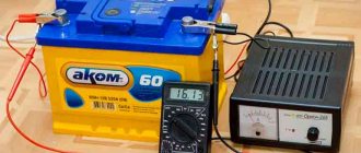
The inverter can be powered through the cigarette lighter in the car using the appropriate cable or directly from the battery.
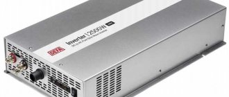
A car inverter is ideal for travel: it is often a small device, about 20 cm long and about 10 cm wide, compact and convenient. Extremely portable and lightweight. Weight – about 1 kg.
A good inverter always has a protection system - a built-in fuse to protect your device. Safe charging design provides protection against overheating, surges, short circuits and overloads.
The durable metal casing provides improved protection against moisture and shock. Built-in ultra-quiet cooling fan helps prevent overheating.
Depending on the planned tasks, when purchasing, be sure to pay attention to the value of the output power that the converter has.
♥ BY TOPIC: How to choose the right external battery (power bank).
What is needed to assemble an inverter
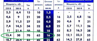
To assemble inverter welding yourself, you need to know that the circuit is designed, first of all, for a consuming voltage of 220 Volts and a current of 32 Amps. After energy conversion, the output current will increase almost 8 times and reach 250 Amperes. This current is sufficient to create a strong seam with an electrode at a distance of up to 1 cm. To implement an inverter-type power supply, you will need to use the following components:
1) A transformer consisting of a ferrite core.
2) Winding of the primary transformer with 100 turns of wire with a diameter of 0.3 mm.
3) Three secondary windings:
— internal: 15 turns and wire diameter 1 mm;
- medium: 15 turns and diameter 0.2 mm;
— external: 20 turns and diameter 0.35 mm.
In addition, to assemble the transformer, you will need the following elements:
- copper wires;
- fiberglass;
— textolite;
— electrical steel;
- cotton material.
Inverter fault detection
The circuits described above often have two specific defects:
- No voltage at the transformer output.
- Low voltage at the transformer output.
Let's look at ways to diagnose these faults:
- Failure of all arms of the converter or failure of the PWM generator. You can check the breakdown using a diode. A working PWM will show ripple on the diode when it is connected to the gates of the transistors. It is also worth checking the integrity of the transformer winding “for an open” in the presence of a control signal.
- A strong drop in voltage is the main sign that one power arm has stopped working. Finding a breakdown is not difficult. A failed transistor will have a cold heatsink. To repair, you will need to replace the inverter key.
What does an inverter welding circuit look like?
In order to understand what an inverter welding machine is, it is necessary to consider the diagram presented below.
Electrical circuit of inverter welding
All these components must be combined and thereby obtain a welding machine, which will be an indispensable assistant when performing plumbing work. Below is a schematic diagram of inverter welding.
Inverter welding power supply diagram
The board on which the device's power supply is located is mounted separately from the power section. The separator between the power part and the power supply is a metal sheet connected electrically to the unit body.
To control the gates, conductors are used, which must be soldered close to the transistors. These conductors are connected to each other in pairs, and the cross-section of these conductors does not play a special role. The only thing that is important to consider is the length of the conductors, which should not exceed 15 cm.
For a person who is not familiar with the basics of electronics, reading this kind of circuit is problematic, not to mention the purpose of each element. Therefore, if you do not have skills in working with electronics, then it is better to ask a familiar specialist to help you figure it out. For example, below is a diagram of the power part of an inverter welding machine.
Diagram of the power part of inverter welding
How do expensive inverters differ from cheap ones?
Unlike most devices and gadgets, the cost of a converter does not depend on the popularity of the brand, but on its power and other functions. Experts divide inverters into three categories:
Up to 300 W – the least powerful models, which are most often connected through the cigarette lighter. Some devices in this category can be connected directly to the car's electrical network, but this will require a lot of effort. Motorists mainly buy such devices to charge mobile devices and some laptop models, although most often it is easier to simply connect the charger to the cigarette lighter.
300 W - 1500 W - standard inverters that are connected to the machine's electrical network. They can be used to connect a TV, microwave oven, laptops and other devices.
Over 1500 W – especially powerful converters that are connected only to the car’s battery. They can be used for work in wild areas (for example, when it comes to construction).
When choosing an inverter, make sure that it exceeds the power of your gadgets by about 20-30%. Connecting a device that is too powerful can result in failure of the inverter and damage to the wiring in the car (at least in theory).
If you intend to use appliances that require at least 220V, choose inverters with a capacity of more than 1500 W, since 300 W models are unlikely to provide voltage above 200V.
Buy an advanced 2000 W inverter with free shipping
Buy an advanced 3000 W high power inverter with free shipping
♥ ON TOPIC: Which TV is better to choose for your home in 2022: 11 practical tips.
How to assemble inverter welding: step-by-step description + (Video)
To assemble an inverter welding machine, you must complete the following work steps:
1) Housing . It is recommended to use an old computer system unit as a housing for welding. It is best suited as it has the required number of holes for ventilation. You can use an old 10-liter canister in which you can cut holes and place the cooler. To increase the strength of the structure, it is necessary to place metal corners from the system housing, which are secured using bolted connections.
2) Assembling the power supply. An important element of the power supply is the transformer. It is recommended to use 7x7 or 8x8 ferrite as the base of the transformer. For the primary winding of the transformer, it is necessary to wind the wire across the entire width of the core. This important feature entails improved operation of the device when voltage surges occur. It is imperative to use PEV-2 copper wires as wire, and if there is no busbar, the wires are connected into one bundle. Fiberglass is used to insulate the primary winding. On top, after the layer of fiberglass, it is necessary to wind turns of shielding wires.
Transformer with primary and secondary windings for creating inverter welding
3) Power part . A step-down transformer acts as a power unit. Two types of cores are used as a core for a step-down transformer: Ш20х208 2000 nm. It is important to provide a gap between both elements, which is solved by placing newsprint. The secondary winding of a transformer is characterized by winding turns in several layers. It is necessary to lay three layers of wires on the secondary winding of the transformer, and fluoroplastic gaskets are installed between them. It is important to place a reinforced insulating layer between the windings, which will avoid voltage breakdown on the secondary winding. It is necessary to install a capacitor with a voltage of at least 1000 Volts.
Transformers for the secondary winding from old TVs
To ensure air circulation between the windings, it is necessary to leave an air gap. A current transformer is assembled on a ferrite core, which is connected to the circuit to the positive line. The core must be wrapped with thermal paper, so it is best to use cash register tape as this paper. Rectifier diodes are attached to the aluminum radiator plate. The outputs of these diodes should be connected with bare wires with a cross-section of 4 mm.
3) Inverter block . The main purpose of an inverter system is to convert direct current into high-frequency alternating current. To ensure an increase in frequency, special field-effect transistors are used. After all, it is the transistors that work to open and close at high frequencies.
It is recommended to use more than one powerful transistor, but it is best to implement a circuit based on 2 less powerful ones. This is necessary in order to be able to stabilize the current frequency. The circuit cannot do without capacitors, which are connected in series and make it possible to solve the following problems:
Aluminum plate inverter
4) Cooling system . Cooling fans should be installed on the case wall, and for this you can use computer coolers. They are necessary to ensure cooling of the working elements. The more fans you use, the better. In particular, it is imperative to install two fans to blow over the secondary transformer. One cooler will blow on the radiator, thereby preventing overheating of the working elements - rectifier diodes. The diodes are mounted on the radiator as follows, as shown in the photo below.
Rectifier bridge on the cooling radiator
It is recommended to use an auxiliary element such as a temperature sensor.
Photo of the thermostat
It is recommended to install it on the heating element itself. This sensor will be triggered when the critical heating temperature of the working element is reached. When it is triggered, the power to the inverter device will be turned off.
Powerful fan for cooling the inverter device
During operation, inverter welding heats up very quickly, so the presence of two powerful coolers is a prerequisite. These coolers or fans are located on the device body so that they work to extract air.
Fresh air will enter the system thanks to the holes in the device body. The system unit already has these holes, and if you use any other material, do not forget to provide a flow of fresh air.
5) Soldering the board is a key factor since the entire circuit is based on the board. It is important to install diodes and transistors on the board in opposite directions to each other. The board is mounted directly between the cooling radiators, with the help of which the entire circuit of electrical appliances is connected. The supply circuit is designed for a voltage of 300 V. The additional arrangement of capacitors with a capacity of 0.15 μF makes it possible to dump excess power back into the circuit. At the output of the transformer there are capacitors and snubbers, with the help of which the overvoltages at the output of the secondary winding are suppressed.
6) Setting up and debugging work . After the inverter welding has been assembled, several more procedures will need to be carried out, in particular, setting up the operation of the unit. To do this, connect a voltage of 15 volts to the PWM (pulse width modulator) and power the cooler. Additionally connected to the relay circuit through resistor R11. The relay is included in the circuit in order to avoid voltage surges in the 220 V network. It is imperative to monitor the relay’s activation, and then apply power to the PWM. As a result, a picture should be observed in which rectangular areas in the PWM diagram should disappear.
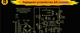
The device of a homemade inverter with a description of the elements
You can judge whether the circuit is connected correctly if the relay outputs 150 mA during setup. If a weak signal is observed, this indicates that the board connection is incorrect. There may be a breakdown in one of the windings, so to eliminate interference you will need to shorten all power supply wires.
Inverter welding in a computer system case
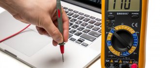
Checking the device's functionality
After all the assembly and debugging work has been completed, all that remains is to check the functionality of the resulting welding machine. To do this, the device is powered from a 220 V power supply, then high current values are set and the readings are verified using an oscilloscope. In the lower loop, the voltage should be within 500 V, but not more than 550 V. If everything is done correctly with a strict selection of electronics, then the voltage indicator will not exceed 350 V.
So, now you can check the welding in action, for which we use the necessary electrodes and cut the seam until the electrode burns out completely. After this, it is important to monitor the temperature of the transformer. If the transformer simply boils, then the circuit has its shortcomings and it is better not to continue the work process.
After cutting 2-3 seams, the radiators will heat up to a high temperature, so after this it is important to allow them to cool down. To do this, a 2-3 minute pause is enough, as a result of which the temperature will drop to the optimal value.
Checking the welding machine
Common Schemes
To convert voltage from one level to another, pulse converters with installed inductive energy storage devices are used. Based on this, three types of conversion schemes are distinguished:
- Inverting.
- Raising.
- Downgrades.
All of the following circuits use electrical components:
- Main switching component.
- Power supply.
- A filter capacitor that is connected in parallel with the load resistance.
- Inductive energy storage (choke, inductor).
- Diode for blocking.
Combining these elements in a certain sequence allows you to build any of the above schemes.
Simple pulse converter
The most basic converter can be assembled from unnecessary parts from an old computer system unit. A significant drawback of this circuit is that the 220V output voltage is far from ideal in its sine wave shape and has a frequency exceeding the standard 50 Hz. It is not recommended to connect sensitive electronics to such a device.
This scheme uses an interesting technical solution. To connect equipment with switching power supplies (for example, a laptop) to the converter, rectifiers with smoothing capacitors are used at the output of the device. The only negative is that the adapter will only work if the polarity of the output voltage of the socket matches the voltage of the rectifier built into the adapter.
For simple energy consumers, the connection can be made directly to the output of transformer TR1. Let's consider the main components of this scheme:
- Resistor R1 and capacitor C2 - set the operating frequency of the converter.
- PWM controller TL494. The basis of the whole scheme.
- Power field effect transistors Q1 and Q2 are used for greater efficiency. Placed on aluminum radiators.
- IRFZ44 transistors can be replaced with IRFZ46 or IRFZ48 with similar characteristics.
- Diodes D1 and D2 can also be replaced with FR107, FR207.
If the circuit involves the use of one common radiator, it is necessary to install transistors through insulating spacers. According to the scheme, the output choke is wound onto a ferrite ring from the choke, which is also removed from the computer power supply. The primary winding is made of 0.6 mm wire. It should have 10 turns with a tap from the middle. A secondary winding consisting of 80 turns is wound on top of it. The output transformer can also be removed from an unnecessary UPS.
The scheme is very simple. When assembled correctly, it starts working immediately and does not require fine tuning. It will be able to supply a current of up to 2.5 A to the load, but the optimal operating mode will be a current of no more than 1.5 A - and this is more than 300 W of power.
INTERESTING: In a store, a similar converter costs around 3-4 thousand rubles.
Converter circuit with AC output
This scheme is also known to radio amateurs of the USSR. However, this does not make it ineffective. On the contrary, it has proven itself very well, and its main advantage is the receipt of stable alternating current with a voltage of 220V and a frequency of 50 Hz.
The K561TM2 microcircuit, which is a dual-type D-trigger, acts as an oscillation generator. This element can be replaced with a foreign analogue CD4013.
The converter itself has two power arms built on KT827A bipolar transistors. They have one significant drawback compared to new field-effect transistors - these components become very hot when open, which is due to high resistance values. The converter operates at low frequency, so a powerful steel core is used in the transformer.
This circuit uses an old TC-180 network transformer. It, like other inverters based on simple PWM circuits, produces a significantly different sinusoidal voltage waveform. However, this drawback is slightly mitigated by the high inductance of the transformer windings and the output capacitor C7.
IMPORTANT: Sometimes the transformer may produce a noticeable hum during operation. This indicates a problem with the circuit.
How to use a homemade device
After connecting a homemade device to the circuit, the controller will automatically set a certain current strength. If the wire voltage is less than 100 Volts, this indicates a malfunction of the device. You will have to disassemble the device and recheck the correct assembly again.
Using this type of welding machine, you can solder not only ferrous, but also non-ferrous metals. In order to assemble a welding machine, you will need not only knowledge of the basics of electrical engineering, but also free time to implement the idea.
Inverter welding is an indispensable thing in any owner’s garage, so if you have not yet acquired such a tool, then you can make it yourself.
How to choose the right car inverter
When choosing a converter, you should consider what devices will be connected to it, as well as a number of other aspects:
1. Car generator power . When buying an inverter, it is worth remembering that its power should not exceed 50% of the generator’s power so that the converter does not drain the battery (at least if household appliances are connected to it). Approximately half of its power will be spent on meeting the needs of the machine's systems, and the rest will go to connected devices. If you do not follow this rule, you risk being left with a dead battery.
2. Devices . The converter should be selected based on the expected power of the equipment used, including data on how much power the gadgets require at startup, in normal mode, and at peak. As mentioned above, only the most powerful converters can provide a voltage of 220 V.
3. Inverter usage model . As a rule, the cigarette lighter in a car produces no more than 100 W, so it is worth considering this aspect if you are looking at an inverter that connects through the cigarette lighter socket. The choice of device can also be influenced by the location where the outlet should be located (inside the cabin or not), as well as the desired power.
4. Brand . High-quality inverters from well-known brands are protected against short circuits and fire, which cannot be said about Chinese devices of dubious origin. When purchasing inverters, it is better to contact large chain stores so as not to end up with a frankly low-quality model.
5. Socket type . When purchasing an inverter, you need to check the type of socket, since not all of them are universal and suitable for all types of plugs.
6. Additional features . High-priced inverters offer a wide range of additional features, such as information screens, voltage changes or USB support. If the functionality is useless to you, it is better not to spend extra money and turn your attention to something simpler.
♥ BY TOPIC: Charging case for iPhone: a selection of the best options in terms of price/quality ratio.