In this article I will talk about how to test a capacitor using a multimeter if you do not have a device for testing the capacitance of capacitors and inductors - an LC - meter.
Polar and non-polar capacitors
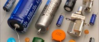
Basically, according to their design, capacitors are divided into two types: polar and non-polar.
Polar capacitors include capacitors that have a polarity, roughly speaking, plus and minus. These most often include electrolytic capacitors, but there are also electrolytic non-polar capacitors. Polar capacitors must be soldered into circuits only in a certain way: the positive contact of the capacitor to the positive circuit, the negative contact to the negative circuit.
If the polarity of such a capacitor is violated, it can be seriously damaged and even explode. Believe me, a capacitor exploding is quite a sight, but the electrolyte contained there can seriously harm you and your surroundings. Basically, this only applies to Soviet capacitors.
Imported capacitors have a small indentation on top in the form of a cross or some other figure. Their thickness is less than the rest of the capacitor cap thickness. As you and I know, where it’s thin, it breaks. This is provided for safety reasons. Therefore, if an imported capacitor nevertheless wants to explode, then its upper part will simply turn into a rosette.
The photo below shows a swollen capacitor on a computer motherboard. The gap goes exactly along the line.
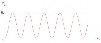
In order to check a capacitor, you need to remember the general property of all capacitors: a capacitor only allows alternating current to pass through, it only allows direct current to pass at the very beginning for a few fractions of a second (this time depends on its capacitance), and then it does not pass through. You can read more about this property in this article. In order to check a capacitor using a multimeter, the condition must be met that its capacitance must be from 0.25 μF.
How to check a polar capacitor
Well, let's check our ward. Here it is, a real imported electrolytic polar capacitor:
In order to figure out where it is minus and where it is plus, the manufacturers applied markings. The minus of the capacitor is indicated by a tick on the body itself. See that black tick on the gold thick capacitor line? It points to the negative terminal.
Let's find out if our patient is alive or dead? First, you need to discharge it with a metal object. I used tweezers.
The next step is to take a multimeter and set its knob to test for continuity or to measure resistance, and use the probes to touch the terminals of the capacitor. Since our multimeter produces a constant current when testing and measuring resistance, it means that at some point in time the current will flow, therefore, at this moment the resistance of the capacitor will be minimal. Next, we continue to hold the probes on the terminals of the capacitor and, without realizing it, we charge it. And while we are charging it, its resistance also begins to increase until it is very high. Let's see in practice what this all looks like.
At this moment we have just touched the capacitor terminals with the probes.
We hold on and see that our resistance is growing
and until it gets very big
An analog multimeter is very convenient for checking capacitors, because you can easily track the smooth movement of a needle than the flickering of numbers on a digital cartoon.
If, when we touch the probes to the capacitor, the multimeter begins to beep and show zero resistance, it means that a short circuit has occurred in the capacitor. And if a 1 is immediately displayed on the multimeter, it means there is a break inside the capacitor. Capacitors with such defects are considered non-functional and can be safely thrown away.
How to test a non-polar capacitor
Non-polar capacitors are even easier to test. We set the measurement limit on the multimeter to Megaohms and touch the leads of the capacitor with the probes. If the resistance is less than 2 Megaohms, then the capacitor is most likely faulty.
Polar and non-polar capacitors with a nominal value of less than 0.25 μF can only be checked for short circuit using a multimeter. To check their functionality, you need a special device - an LC meter or a universal R/L/C/Transistor-meter, but some multimeters can also measure the capacitance of capacitors, having such a function inside them. For example, my multimeter can easily determine the capacitance of a capacitor up to 200 µF. Please note that there is a fuse inside the multimeter. If it burns out, then some functions of the multimeter are lost. On my multimeter, when the internal fuse blew, the current measurement function and capacitance measurement function did not work.
Basic parameters of capacitors
The capacitance of a capacitor characterizes the energy that the capacitor is capable of accumulating, as well as the current that it is capable of passing through itself. Measured in Farads with a multiplying prefix (nano, micro, etc.).
The most commonly used values for run and start capacitors range from 1 μF to 100 μF.
The rated voltage of a capacitor is the voltage at which the capacitor is able to operate reliably and for a long time, maintaining its parameters.
Well-known capacitor manufacturers indicate on its body the voltage and the corresponding guaranteed operating time in hours, for example:
- 400 V – 10000 hours
- 450 V – 5000 hours
- 500 V – 1000 hours
Calculation of required capacity
When choosing a capacitor, it is necessary to prevent a situation in which the phase current exceeds its rated value. Therefore, the calculations must be approached very carefully - incorrect results can lead not only to capacitor failure, but also to burnout of the motor windings. In practice, to start small-power motors, a simplified selection is used based on the considerations that for every 100 W of motor power, 7 μF of capacitance is required when connected in a triangle. When connecting the winding in a star, this value is halved. If a three-phase motor with a power of 1 kW is connected to a single-phase network, then a capacitor with a charge of 70-72 μF is required when the windings are connected in a triangle, and 36 μF in the case of a star connection.
It will be interesting➡ What is the polarity of a capacitor and how to determine it?
The required capacity value for operation is calculated using formulas.
With a star connection:
Wed=2800 I/U
If the windings form a triangle:
Wed=4800 I/U
I is the rated current of the motor. If for some reason its value is unknown, you must use the formula for calculation:
I = P / (3 U).
In this case, U = 220 V when connected by a star, U = 380 V when connected by a triangle.
P is power, measured in watts.
When starting an engine with a significant load on the shaft, it is necessary to turn on the starting gear in parallel with the working tank.
Its value is calculated using the formula:
Sp=(2.5÷3.0) Avg
The starting capacity should exceed the operating capacity by 2.5 - 3 times.
Material on the topic: all about the variable capacitor.
The correct choice of voltage value for the capacitor is very important. This parameter, as well as capacity, affects the price and dimensions of the device. If the mains voltage is greater than the rated value of the capacitor, the starting device will fail. But you shouldn’t use equipment with too much voltage either. After all, this will lead to an ineffective increase in the dimensions of the capacitor bank. The optimal capacitor voltage value is 1.15 times higher than the network voltage: Uk = 1.15 U s.
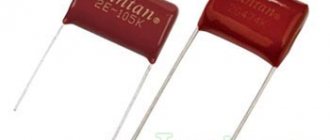
Very often, when connecting a motor with three windings to a single-phase network, capacitors of the KGB-MN or BGT type (heat-resistant) are used. They are made of paper. The metal case is completely sealed. Has a rectangular appearance. It must be taken into account that the permissible voltage and capacitance values indicated on the device are indicated for direct current. Therefore, when operating on alternating current, it is necessary to reduce the capacitor voltage by 2 times.
Calculation of the required capacity.
Checking the starting and running capacitors
You can check the capacitor using a capacitor capacitance meter; such devices are produced both separately and as part of a multimeter, a universal device that can measure many parameters. Let's consider checking with a multimeter.
- de-energize the air conditioner
- discharge the capacitor by short-circuiting its terminals
- remove one of the terminals (any)
- We set the device to measure the capacitance of capacitors
- We lean the probes against the terminals of the capacitor
- read the capacity value from the screen
All devices have different designations for the capacitor measurement mode; the main types are shown below in the pictures.
In this multimeter, the mode is selected by a switch; it must be set to Fcx mode. The probes must be inserted into the sockets marked Cx.
Switching the capacitance measurement limit is manual. Maximum value 100 µF.
This measuring device has an automatic mode, you just need to select it, as shown in the picture.
The Mastech measuring tweezers also automatically measure capacitance, you just need to select the mode with the FUNC button, pressing it until the F indication appears.
To check the capacitance, we read its value on the capacitor body and set a deliberately larger measurement limit on the device. (If it's not automatic)
For example, the nominal value is 2.5 μF (μF), on the device we set 20 μF (μF).
After connecting the probes to the terminals of the capacitor, we wait for the readings on the screen, for example, the time to measure a capacitance of 40 μF with the first device is less than one second, with the second one – more than one minute, so you should wait.
If the rating does not correspond to that indicated on the capacitor body, then it must be replaced and, if necessary, an analogue must be selected.
Capacitor Capacitance Measurement
Capacitance measurement
Capacitance is the main characteristic of a capacitor. It is indicated on the outer shell of the device, and if you have a tester, you can measure the real value and compare it with the nominal value.
The multimeter switch is switched to the measurement range. The value is set equal to or close to the value indicated on the component. The capacitor itself is installed in special holes –CX+ (if they are on the multimeter) or using probes. The probes are connected in the same way as when measuring in resistance mode.
When connecting the probes, the resistance value should appear on the monitor. If it is close to the nominal characteristic, the capacitor is working. When the discrepancy between the received and nominal values differs by more than 20%, the device is broken and needs to be replaced.
Replacement and selection of starting/running capacitor
If you have an original capacitor, then it is clear that you simply need to put it in place of the old one and that’s it. Polarity does not matter, that is, the terminals of the capacitor do not have the designations plus “+” and minus “-” and they can be connected in any way.
It is strictly forbidden to use electrolytic capacitors (you can recognize them by their smaller sizes, with the same capacity, and the plus and minus markings on the case). As a consequence of application - thermal destruction. For these purposes, manufacturers specially produce non-polar capacitors for operation in an alternating current circuit, which have convenient mounting and flat terminals for quick installation.
If the required value is not available, then it can be obtained by connecting capacitors in parallel . The total capacitance will be equal to the sum of the two capacitors:
That is, if we connect two 35 μF capacitors, we get a total capacity of 70 μF, the voltage at which they can operate will correspond to their rated voltage.
Features of a three-phase motor
Asynchronous electric motors with three stator windings predominate in various agricultural sectors. They are used to drive ventilation devices, remove manure, prepare feed, and supply water. The popularity of such motors is due to a number of advantages:
- simplicity of structure;
- reliability in operation;
- when connected in normal mode, expensive and scarce devices are not used;
- the number of technical services is small.
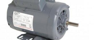
You can try to connect a three-phase motor to 220, knowing the differences in winding connection diagrams. The number of phases for which the motor is designed can be determined by the number of terminals in its terminal box: a three-phase motor will have 6 terminals, and a single-phase motor will have two or four. The three-phase motor windings are connected according to a set pattern called “star” or “delta”. Each of them has its own advantages and disadvantages. In a star connection, the ends of the windings are connected. In the terminal box, this connection diagram will be displayed using two jumpers between the terminals labeled “C6”, “C4”, “C5”.
If the motor windings are connected in a triangle, then a beginning is attached to each end. The terminal box will use three jumpers that will connect the terminals “C1” and “C6”, “C2” and “C4”, “C3” and “C5”. Three-phase motors are designed for an operating voltage of 380 V. But such voltage is not always available in everyday life. Therefore, a problem arises: how to connect an electric motor through a capacitor to a household network?
The most acceptable and widely available method is to use a phase-shifting capacitor. In this mode, 50–60% of the nominal power can be achieved. Note that not all asynchronous motors will work equally well when connected to a single-phase network. The engines most adapted to these conditions are those with a squirrel-cage rotor made in the form of a double cage.
Related material: Types of capacitor connections
Optimal operation of the electric motor is achieved only if the capacitance of the capacitor changes as the rotation speed increases. In practice it is very difficult to implement this requirement. In this regard, two-stage motor control is adopted. Starting is carried out using two capacitors (starting - Sp and working - Wed). Then, when the desired rotation speed is reached, the starter must be turned off. Its main function is to increase the starting torque.
It will be interesting➡ How are capacitors indicated on the diagram?
The calculation of a capacitor for an electric motor can be done in this way. The calculation formula looks like: Ср = К*(In/U). The following notations are used here:
- current strength (nominal) - In (A);
- voltage (nominal) - U (V);
K is a dimensionless coefficient.
The value of K is determined by how the engine is turned on. K = 2800 when the engine is turned on in a star configuration. If it is connected according to the “triangle” circuit, then the value K = 4800.
It is recommended to choose paper capacitors for starting an electric motor, in particular:
- paper, sealed, in a metal case, marked KBG-MN
- paper, heat-resistant, symbol BHT;
- metal-paper, frequency, MBGCH.
If it is necessary to change the direction of rotation of the motor, it is enough to swap the wires connected to the terminals of the capacitor. It is better to start an electric motor using a capacitor using a delta circuit. In this case, you can achieve maximum output power (up to 70%). As an example, consider the AO2 engine. Its rated power is 2.2 kW, rotation speed is 1420 rpm. To start it in idle mode (or when there is a load), you will need 2 capacitors: the first with a capacity of 230 μF (working) and the second with a capacity of 150 μF (starting).
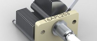
Large capacity starting capacitors.
How to check the capacitance of a capacitor with a multimeter
If you know how to check the performance of a capacitor with a multimeter, you can avoid many troubles. To do this, they test the main characteristics and parameters that affect the operation. The following is indicated on the radio component housing:
- Nominal capacity. Its value affects the amount of accumulated energy on the plates, which is formed during charging from a constant voltage source and is consumed in the electrical circuit during discharge.
- Rated voltage. An incorrectly selected value will lead to dielectric breakdown.
To determine faults, you need to understand the types of capacitors; they are polar and non-polar.
Polar are electrolytic ones that have a negative and a positive terminal. Polarity is indicated on the body (a minus is indicated by a tick) or determined by size - the terminal with a plus is longer. It is important to connect the electrical measuring instrument correctly to test electrolytic capacitors: connect the “+” probe to the positive terminal, and the “-” probe to the negative terminal. This connection is also made when installing electrical circuits.
The remaining types are non-polar, so the method of connection to the tester is not important.
Measuring resistance
You can check the serviceability of the capacitor by determining the resistance using the ohmmeter mode. In this case they check:
- internal break;
- breakdown
- short circuit.
If the part is included in the circuit, it is desoldered. Follow these steps:
- Inspect the appearance. Bulging, smudges, darkening, and loose terminals indicate a malfunction.
- The capacitor is discharged with a metal object, using a screwdriver or tweezers. Holding the handle of the tool, touch two terminals at once. During a discharge, a spark may appear.
- Set up the device to check the condition of the capacitor, use the ohmmeter function. Use the pointer to select the measurement limit in the Ω sector or continuity.
- Connect the probes of the electrical measuring device to the radio component. If it is necessary to check an electrolytic capacitor, then take into account the polarity.
- At the initial moment of time, the multimeter’s power source charges the radio component, the charging speed is directly proportional to the capacity.
- Based on the digital multimeter display, a conclusion is made about the operability of:
- if, with increasing charge, the reading smoothly increases from 0 to 1 (corresponds to infinity) – there is no malfunction;
- if the number 1 appears immediately – damage (break);
- if the number 0 appears immediately, there is a malfunction (short circuit or breakdown).
Using an analog device, the procedure for determining damage is repeated. The deviation of the arrow determines suitability for work:
- smooth movement from 0 to the maximum value – there is no malfunction;
- the arrow remains at 0 – short circuit, replacement required;
- the arrow immediately shows the maximum value - break.
To test a non-polar capacitor:
- first discharge;
- select the ohmmeter mode on the measuring device;
- set the measurement limit to megaohms;
- connect the tester to the capacitor;
- take a reading: if the resistance value is less than 2 megohms - there is a malfunction, more than 2 megohms or 1 - there is no malfunction.
Breakdown is determined as follows:
- supply voltage exceeding the rated voltage;
- resistance is measured: during breakdown it does not change.
Measuring capacity
To test the capacitance of a capacitor, the multimeter must have this function. To make measurements, use Cx sockets with “plus” and “minus” polarities. When testing, the resulting value is compared with the nominal value. Procedure:
- Remove the charge.
- The switch sets the capacitance measurement limit in accordance with the rating.
- Use Cx sockets for measurement. If the element is electrolytic, pay attention to the polarity: the “positive” terminal is connected to the “+” socket, the “negative” terminal is connected to the “-” socket. They take the reading.
- Compare the measured value with the nominal value. If there is no large deviation, there is no malfunction. Otherwise, replacement is required.
Safety precautions when working with capacitors
To prevent touching live areas, the latter must be insulated with a casing device or a fence in the form of a mesh. It is necessary to properly strengthen the body of the device so that it does not move or fall out of the area allocated for it due to shaking and vibrations that occur during operation. Before carrying out the test and initial connection to the circuit, you must make sure that the device is completely discharged. Discharge can be carried out using a resistor. It is advisable to do this every time after switching off, since elements of this group tend to store the accumulated charge for a long time.
These products are small capacity devices suitable for installation in electrical circuits
For correct operation, it is important to select the correct rating and connect the components in the circuit
Checking without instruments
Without measuring parameters, a malfunction is indicated by appearance defects:
- stains on the surface of the body;
- swelling, deformation of the upper notch on imported electrolytic capacitors;
- electrolyte leakage.
Other methods of troubleshooting are used at home. You should:
- connect to a power source, the voltage should not exceed the rated voltage;
- take an LED (low-voltage lamp with two wires), touch the leads of the LED to the legs of the capacitor;
- LED flash (short-term glow of the lamp) will confirm serviceability.
To determine the performance of a large capacitor:
- connect to a power source whose voltage is less than the rated voltage;
- remove the charge with a metal object.
The presence of a spark during discharge will confirm suitability. When removing a charge, be careful and take protective measures, as the discharge is accompanied by a powerful spark and sound. To reduce the spark, a discharge is used through a resistor.
Features of testing different types of capacitors
There are many types of radio components that differ in the material of the dielectric, plates, and type of electrolyte, so they have different methods for diagnosing the operating condition.
To check the suitability of a ceramic capacitor, set the highest measurement limit of the ohmmeter. A sign of serviceability will be a measured resistance of at least 2 MOhm. For other values, the part is changed.
To test a tantalum capacitor, select the largest measurement limit in ohms. If the resistance is 0, change it. Before testing a high-capacity, high-voltage electrolytic capacitor, maximum discharge is necessary. Residual voltage will damage the device.
SMD capacitors are non-polar, so they are tested like ceramic ones, determining suitability using an ohmmeter.
For a film capacitor with a short circuit, the reading will be 0. If there is an internal break, the analog multimeter will show infinity, the digital multimeter will show 1.
Testing without soldering
It is impossible to examine a radio component without desoldering; the reading will be incorrect due to the influence of other elements of the circuit. The proximity of transformers, inductance, and fuses introduces an error into the measurement. Connecting them in parallel or in series will increase or decrease the test result. To correctly assess the condition, the capacitor is desoldered.
Without soldering, you can approximately determine the operation of a section of the circuit. To do this, touch the legs of the part with probes and measure the resistance. If the reading increases and then decreases, the part is working properly.
It must be remembered that capacitor monitoring is only possible up to a maximum value of 200 µF. Electrical measuring instruments do not measure large parameters. If the value is less than 0.25 µF, the capacitors are checked only for short circuits.
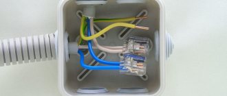
Connection diagrams
wiring diagram for an electric motor with a starting capacitor
The circuit that has a starting capacitor in the network has become more widespread.
This scheme has certain nuances:
- The starting winding and capacitor are turned on when the engine starts.
- The additional winding operates for a short time.
- The thermal relay is included in the circuit to protect the additional winding from overheating.
If it is necessary to provide high torque during startup, a starting capacitor is included in the circuit, which is connected together with the working capacitor. It is worth noting that quite often its capacity is determined empirically to achieve the highest starting torque. Moreover, according to the measurements taken, the value of its capacity should be 2-3 times greater.
The main points of creating an electric motor power circuit include the following:
- From the current source , 1 branch goes to the working capacitor. It works all the time, which is why it got its name.
- In front of it there is a branch that goes to the switch. In addition to the switch, another element can be used that starts the engine.
- after the switch . It operates for a few seconds until the rotor picks up speed.
- Both capacitors go to the motor.
In a similar way, you can connect a single-phase electric motor.
It is worth noting that the working capacitor is present in the circuit almost constantly. Therefore, it is worth remembering that they must be connected in parallel.