We need to bring some order to the terminology. Starters and contactors are often confused . To some they are the same thing, and some say that a contactor is just a big, powerful starter. But no one can really explain how powerful it is...
Previously, during the Soviet era, this was the case. Now starters that were produced or developed in those days are called starters (for example, PML, which is still produced in Ukraine), and new and foreign models are called contactors.
Electricians call the same devices starters, and sellers call them contactors. To be honest, I’m more used to talking about starters.
Types of magnetic starters
The main purpose of magnetic starters is remote control of three-phase asynchronous electric motors with a squirrel-cage rotor. They operate at alternating current voltages of 380 and 660 volts, with a frequency of 50 Hz. Basic operations include starting, stopping and reversing.
Additionally, magnetic starters in combination with thermal relays protect controlled electric motors from possible overloads with an unacceptable duration. Some starter designs include surge suppressors used in solid-state control systems.
In accordance with the switching diagram, the loads can be reversible or non-reversible. Classification by placement assumes magnetic starters of the following types:
- Open version. Installed in closed cabinets, on panels, and other places where dust, moisture and foreign objects cannot enter.
- Secure execution. Installed indoors with low dust content in the environment. Prevents water from entering the device shell.
- Dust-splash-proof design. They are installed indoors and outdoors under canopies that protect from rain and sunlight.
Additional classification of starters is carried out according to the following criteria:
- Push-button station on the device body. Irreversible starters are equipped with START and STOP buttons, and reversing devices have START FORWARD, START REVERSE and STOP buttons. On some models, an ON indicator light is mounted in the housing.
- Additional blocking and signal contacts. They are used in different combinations, as making or breaking switches. They can be built-in or equipped as a separate console. Some additional contacts can be used as part of the overall starter circuit. For example, in reversing devices they are used to provide electrical locking.
- Coil current and voltage.
- The presence of a thermal relay in the circuit. Its main characteristic is the rated non-operation current at medium installations. The non-operation current is adjusted within acceptable limits + 15% of the nominal value.
Certain types of magnetic starters can be equipped with surge suppressors and other types of installation products
Electromagnetic starters
Purpose and varieties
An electromagnetic starter is a device designed for remote control of power loads (lighting, electric heating devices, electric motors).
Note. The starter was created to control asynchronous electric motors with a squirrel-cage rotor.
in the starter
, as a complete device, may include control buttons, thermal protection relays, and signal lamps located in one housing.
Magnetic starters differ in purpose (irreversible, reversible), the presence or absence of thermal relays, control buttons, degree of protection from environmental influences, levels of switched currents, and operating voltage of the coil.
The most common series of starters with a contact system and electromagnetic drive: PME, PMA, PA, PVN, PML, PV, PAE, PM12.
Selecting an electromagnetic starter
Let's consider the main parameters for choosing an electromagnetic starter.
Electromagnetic starter series.
The most widely used are starters of the PML and PM12 series, as well as more expensive, but also higher quality starters of the PMU series and foreign companies.
Legrand, ABB, Schneider Electric.
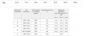
Electromagnetic starters are: 1st magnitude (main contact current - 10 and 16 A); 2nd magnitude (25 A); 3rd magnitude (40 A); 4th magnitude (63 A).
Note.
If current loads exceed 63 A, then electromagnetic contactors .
The current of the main contacts of the device must be greater than the maximum load current (the operating current of an electric motor or other electrical receiver, for which we select a starter to turn on). Coil operating voltage.
Must correspond to the voltage of the control circuits - standard voltage values are ~24 V, ~110 V,
~220 V, ~380 V, DC 24 V.
Number of additional contacts of the electromagnetic starter.
This parameter must correspond to the required number of contacts in the control circuit. Separately, it is necessary to count the NO and NC contacts. If the number of contacts of the device is less than required and the PML series was selected as the device, then you can use an attachment with additional contacts of the PKL series.
There is another type of consoles - PVL
. Unlike PKL attachments, these attachments can slow down the actuation of contacts for a short time, i.e., in fact, PML series starters with PVL attachments can be used as a simple time relay (sometimes for simple circuits this option is cheaper than installing a conventional relay time).
Degree of protection, IP.
IP - XX
The first digit of the code: the degree of protection of personnel from contact with live parts and from contact with moving parts located inside the enclosure, as well as the degree of protection of the product from the ingress of solid foreign bodies:
0—no protection.
1 - protection against penetration into the shell of live and moving parts of a large area of the surface of the human body and protection against penetration of solid bodies larger than 50 mm under the shell.
2 - protection against penetration into the shell of live and moving parts of fingers or objects longer than 80 mm and against penetration of solid bodies larger than 12 mm.
3 - protection against penetration into the shell of live moving parts of tools, wire, etc. with a diameter or thickness of more than 2.5 mm and from penetration of solid bodies larger than 2.5 mm.
4 - protection against penetration into the shell of live and moving parts of wire and other objects with a thickness of more than 1 mm, and against penetration of solid bodies with a size of more than 1 mm.
5 - complete protection of personnel from accidental contact with live moving parts located under the shell; Ingress of dust is not completely prevented, but dust cannot enter in sufficient quantities to impair the operation of the product
6 - complete protection of personnel from accidental contact with live and moving parts and complete protection from dust penetration.
The second digit of the code: the degree of protection of the product from moisture: 0 - no protection.
1 - protection against water drops. Drops of water falling vertically onto the shell should not have a harmful effect on the product.
2 - protection from drops of water falling on the shell at an inclination of 15 degrees. Drops should not have a harmful effect on the product.
3 - protection from rain. Rain falling on the enclosure at an angle of 60° from the vertical shall not have any harmful effect on the product located under the enclosure.
4 - protection against splashes falling from any angle. Splashes should not have a harmful effect on the product located under the shell.
5 - protection against water jets. A stream of water, which is thrown in any direction onto the shell, must not have any harmful effect on the product.
6 - protection from impacts typical of a ship’s deck (including deck waterproof equipment).
7 - protection when immersed in water. Water shall not penetrate into an enclosure immersed in water, under certain conditions of pressure and time, in sufficient quantities to damage the product.
8 - protection during prolonged immersion in water. The products are suitable for prolonged immersion in water under the conditions specified by the manufacturer.
The magnetic starter must be suitable for the environmental conditions in which it operates. It must be taken into account that a device installed in a dusty room, but located in a control cabinet with degree of protection IP44, may have degree of protection IP20.
The presence of a thermal relay.
If an electromagnetic starter turns on and off electric motors that are experiencing overloads, then it is necessary to choose a device with thermal relays.
Presence of reverse.
To control a reversible electric motor, it is possible to use a reversible magnetic starter, which contains 2 electromagnetic coils, 6 power contacts, and a mechanical interlock.
Additional controls
(buttons on the body, light bulb).
Wear resistance class
(number of operations). This is an important parameter in the case when the device is intended for switching a load operating in the mode of frequent switching on and off. If the number of starts and stops per hour is large, contactless starters are used.
If you comply with the above conditions and requirements, the selected device will work reliably and last as long as possible. It is important to consider that the reliability and trouble-free operation of any electrical device depends on its proper operation.
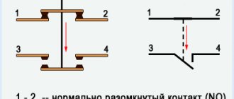
Magnetic starter connection diagram
In Fig. 10 shows the installation and circuit diagram of switching on an irreversible magnetic starter for controlling an asynchronous electric motor with a squirrel-cage rotor. On the wiring diagram, the boundaries of one device are outlined with a dashed line.
In the circuit diagram, all elements of one magnetic starter have the same alphanumeric designations. This allows you to avoid linking conventional images of the contactor coil and contacts together, achieving the greatest simplicity and clarity of the circuit.
Rice.
10. Switching diagram of an irreversible magnetic starter: a - installation;
b - electric Irreversible magnetic starter
has a KM contactor with three main make contacts (L1 - C1, L2 - C2, L3 - C3) and one auxiliary make contact (3-5).
Main circuits
, through which the electric motor current flows, are usually depicted with thick lines, and
the power circuits of the starter coil
(or control circuit) with the highest current are depicted with thin lines.
To turn on the electric motor M, you must briefly press the SB2 “Start” button. Current will flow through the coil circuit of the magnetic starter, and the armature will be attracted to the core. This will close the main contacts in the motor power supply circuit. At the same time, auxiliary contact 3-5 will close, which will create a parallel power circuit for the magnetic starter coil.
If the “Start” button is released, the magnetic starter coil will be turned on through its own auxiliary contact. This type of circuit is called a self-locking circuit.
.
It provides so-called zero motor protection
. If during operation of the electric motor the voltage in the network disappears or decreases significantly (usually by more than 40% of the nominal value), then the magnetic starter is turned off and its auxiliary contact opens.
After the voltage is restored, to turn on the electric motor, you must press the “Start” button again.
Attention. Zero protection prevents unexpected, spontaneous starting of the electric motor, which can lead to an accident.
Manual control devices (switches, limit switches) do not have zero protection, therefore, in machine drive control systems, control using magnetic starters is usually used.
To turn off the electric motor, just press the SB1 button
"Stop". This leads to the opening of the self-supply circuit and the disconnection of the magnetic starter coil.
Connection diagram for reversing magnetic starter
In the case when it is necessary to use two directions of rotation of the electric motor, a reversible magnetic starter is used, the circuit diagram of which is shown in Fig. 11, a.
Let's consider the principle of operation of switching circuits for a reversible magnetic starter.
To change the direction of rotation of an asynchronous electric motor, it is necessary to change the phase sequence of the stator winding.
The reversible magnetic starter uses two contactors: KM1 and KM2. From the diagram ( Fig. 11, a
) it can be seen that if both contactors are accidentally switched on simultaneously, a short circuit will occur in the main current circuit.
To eliminate this, the circuit is equipped with a lock
.
If, after pressing the SB3 “Forward” button to turn on the KM1 contactor, press the SB2 “Back” button, then the opening contact of this button will turn off the KM1 contactor coil, and the closing contact will supply power to the KM2 contactor coil. The motor will reverse.
Rice.
11. Connection diagrams: a - circuit diagram of the starter;
b - schematic diagram of the control circuit of a reversing starter with interlocking on auxiliary opening contacts. The electrical diagram of the control circuit of a reversing starter with interlocking on auxiliary opening contacts is shown in Fig. 11, b
. In this circuit, turning on one of the contactors, for example KM1, opens the power circuit of the coil of the other contactor KM2. To reverse, you must first press the SB1 button
“Stop” and turn off the KM1 contactor.
Attention. For reliable operation of the circuit, it is necessary that the main contacts of the KM1 contactor open before the closing of the breaking auxiliary contacts in the KM2 contactor circuit occurs. This is achieved by appropriate adjustment of the position of the auxiliary contacts along the armature.
In serial magnetic starters, double blocking
according to the above principles. Reversible magnetic starters can have a mechanical interlock with a changeover lever that prevents the simultaneous operation of the contactor electromagnets. In this case, both contactors must be installed on a common base.
Adjustment and operation of electromagnetic starters and contactors
Magnetic starters and contactors are checked and adjusted according to the following program:
- visual inspection;
— adjustment of the magnetic and contact system;
— checking the insulation resistance of live parts.
Upon external examination
contactors and magnetic starters, first of all, pay attention to the condition of the main and blocking contacts, the magnetic system, check the presence of all contactor parts: non-magnetic gasket for a DC contactor, mounting bolts, nuts, washers, short-circuited coil for AC contactors, arc chutes .
Ease of movement of the contactor
checked by closing it by hand. The movement of the magnetic system should be smooth, without jolts or jams.
The AC contactor should make only a slight noise when current flows through the coil. A strong contactor hum may indicate improper attachment of the armature or core, damage to the short-circuited turn surrounding the core, or a loose fit of the armature to the electromagnet core. To eliminate excessive humming, tighten the screws securing the armature and core.
The tightness of the armature to the core
check as follows. Place a piece of paper between the armature and the core and close the contactor by hand. The contact area must be at least 70% of the cross-section of the magnetic core; with a smaller contact area, the defect is eliminated by correct installation of the core and armature. When a general gap is formed, the surface is scraped along the layers of sheet steel of the magnetic system.
As the DC contactor operates, abrasion of the non-magnetic pad may occur, which reduces the gap and promotes sticking of the armature to the core. Therefore, if there is significant wear, the gasket is replaced with a new one.
Attention. The contact system is the most critical part of the contactors of magnetic starters, therefore special attention should be paid to its condition.
In the closed state, the contacts should touch each other with their lower parts, forming a linear contact along the entire width of the contact without gaps. The presence of sagging or frozen pieces of metal on the contact surface increases the contact resistance (and, consequently, losses in contacts) by more than 10 times. Therefore, if sagging is detected, it is necessary to remove them with a file.
Note. Sanding and lubricating the contact surface is not allowed.
In especially critical contactors and magnetic starters, the initial and final pressing forces of the main contacts are determined. Initial Press
— the force created by the contact spring at the moment of contact of the contacts characterizes the elasticity of the spring.
The final pressing force
characterizes the pressure on the contacts when the contactor is fully switched on and the contacts are not worn. The initial and final pressing forces are determined using a dynamometer.
Insulation resistance of live parts
Contactors and magnetic starters are checked with a 500 or 1000 V megohmmeter. The insulation resistance value of the coil should not be lower than 0.5 MOhm.
In addition to the above work, the setup program may include the following:
— checking the absence of short-circuited turns in the coil;
— checking contactors by repeated switching on and off;
— setting up thermal relays of magnetic starters.
Malfunctions of electromagnetic starters and methods for their elimination
Different timing of closure and state of the main contacts.
The difference in the closing time of the main contacts can be eliminated by tightening the clamp holding the main contacts on the shaft. If there are traces of oxidation, deposits or frozen drops of metal on the contacts, the contacts must be cleaned.
Strong humming from the magnetic system of the electromagnetic starter.
A strong hum from the magnetic system may indicate incorrect operation, which can lead to failure of the starter coils. During normal operation, the starter makes only a slight noise.
To eliminate the hum, the starter must be turned off and checked:
- tightening the screws securing the armature and core;
— whether the short-circuited turn placed in the slots of the core is damaged. Since alternating current flows through the coil, the magnetic flux changes its direction and at some points in time becomes equal to zero. In this case, the counteracting spring will tear the armature away from the core and armature chatter will occur. A short-circuited turn eliminates this phenomenon;
- the state of the contact surface of both halves of the electromagnetic system of the starter and the accuracy of their fit, since in electromagnetic starters the current in the winding strongly depends on the position of the armature. If there is a gap between the armature and the core, the current passing through the coil is greater than the rated one.
To check the accuracy of contact between the armature and the core of the electromagnetic starter, you can place a piece of copy paper and a piece of thin white paper between them and close the starter by hand. The contact surface must be at least 70% of the cross-section of the magnetic core. With a smaller contact surface, this defect can be eliminated by correctly installing the core of the electromagnetic system of the starter. If a general gap has formed, then it is necessary to scrape the surface along the layers of sheet steel of the magnetic system.
Lack of reverse in reversible magnetic starters.
The lack of reverse in reversing starters can be eliminated by adjusting the mechanical locking rods
Sticking of the armature to the starter core.
Sticking of the armature to the core occurs as a result of the absence of a non-magnetic gasket or its insufficient thickness. The starter may not turn off even if the voltage from the coil is completely removed. It is necessary to check the presence and thickness of a non-magnetic gasket or air gap.
When turned on, the starter becomes self-locking.
It is necessary to check the condition of the starter blocking contacts. The contacts in the on position must fit tightly against each other and turn on simultaneously with the main contacts of the starter. Block contact gaps (the shortest distance between an open moving and a fixed contact) must not exceed the permissible values. It is necessary to adjust the starter block contacts. If the failure of the block contact becomes less than 2 mm, then the block contacts must be replaced.
Timely testing and adjustment of electromagnetic starters allows you to avoid problems and damage in advance.
Rules for installing a magnetic starter
If the device was installed incorrectly, there is a high probability that it will work with false alarms. Therefore, some useful tips:
- Do not install the starter in areas that are subject to vibration or shock loads.
- Installation is usually carried out in an electrical panel. But there are also rules here, the first of which is that the installation site must be flat, vertical and level.
- It should not be exposed to heat from any sources. This may cause the thermal relay to trip on its own.
- The switchboard cannot be installed in rooms where there is electrical equipment with a current higher than 150A. the whole point is that starting and stopping such equipment is accompanied by a shock.
- If one end of the wire is inserted into the contact clamp, then it must be bent in the shape of the letter “P”.
- If two ends of the wire are inserted into the clamp at once, then they are installed on both sides of the screw, and they must be straight, not bent.
- Before making the first start, the magnetic starter must be checked for technical condition and for correct connection of the contacts.
Installation is carried out in the panelSource tehnormal.by
Connection diagrams for a magnetic starter with a 220 V coil
Before we move on to the diagrams, let’s figure out what and how these devices can be connected. Most often, two buttons are required - “start” and “stop”. They can be made in separate housings, or they can be a single housing. This is the so-called push-button post.
Buttons can be in the same housing or in different ones
Everything is clear with individual buttons - they have two contacts. One receives power, the other leaves it. There are two groups of contacts in the post - two for each button: two for start, two for stop, each group on its own side. There is also usually a ground terminal. Nothing complicated either.
Connecting a starter with a 220 V coil to the network
Actually, there are many options for connecting contactors; we will describe a few. The diagram for connecting a magnetic starter to a single-phase network is simpler, so let's start with it - it will be easier to understand further.
Power, in this case 220 V, is supplied to the coil terminals, which are designated A1 and A2. Both of these contacts are located at the top of the case (see photo).
This is where you can supply power to the coil.
If you connect a cord with a plug to these contacts (as in the photo), the device will be in operation after the plug is inserted into the socket. In this case, any voltage can be applied to the power contacts L1, L2, L3, and it can be removed when the starter is triggered from contacts T1, T2 and T3, respectively. For example, a constant voltage from a battery can be supplied to the inputs L1 and L2, which will power some device that will need to be connected to the outputs T1 and T2.
Connecting a contactor with a 220 V coil
When connecting single-phase power to the coil, it does not matter which output is supplied with zero and which with phase. You can switch the wires. Even most often, the phase is supplied to A2, since for convenience this contact is located on the bottom side of the housing. And in some cases it is more convenient to use it and connect the “zero” to A1.
But, as you understand, this scheme for connecting a magnetic starter is not particularly convenient - you can also supply conductors directly from the power source by building in a regular switch. But there are much more interesting options. For example, you can supply power to the coil through a time relay or a light sensor, and connect the street lighting power line to the contacts. In this case, the phase is connected to contact L1, and zero can be taken by connecting to the corresponding coil output connector (in the photo above it is A2).
Diagram with start and stop buttons
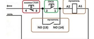
Magnetic starters are most often installed to turn on an electric motor. It is more convenient to work in this mode if there are “start” and “stop” buttons. They are connected in series to the phase supply circuit to the output of the magnetic coil. In this case, the diagram looks like the figure below. note that
Switching diagram of a magnetic starter with buttons
But with this method of switching on, the starter will operate only as long as the “start” button is held down, and this is not what is required for long-term operation of the engine. Therefore, a so-called self-catching circuit is added to the circuit. It is implemented using auxiliary contacts on the starter NO 13 and NO 14, which are connected in parallel with the start button.
Connection diagram for a magnetic starter with a 220 V coil and a self-retaining circuit
In this case, after the START button returns to its original state, power continues to flow through these closed contacts, since the magnet has already been attracted. And power is supplied until the circuit is broken by pressing the “stop” key or by triggering a thermal relay, if there is one in the circuit.
Power for the motor or any other load (phase from 220 V) is supplied to any of the contacts marked with the letter L, and is removed from the contact marked T located underneath it.
It is shown in detail in what order it is better to connect the wires in the following video. The whole difference is that not two separate buttons are used, but a push-button post or push-button station. Instead of a voltmeter, you can connect a motor, pump, lighting, or any device that operates on a 220 V network.
What is the difference between magnetic starters and contactors?
Both devices are switching devices, that is, they control power networks. And more often they are installed in the electric motor starting system. In both devices, in addition to power contacts, there is at least one, and often more, which is used for the control circuit.
Otherwise they differ. Firstly, in size and weight. Starters are much more compact. At the same time, their weight is much less. For example, if you take both devices of the same rating in different hands, the contactor will be many times heavier. In addition, it should be noted that contactors that would be designed for low currents simply do not exist. They are replaced in power networks by starters.
Secondly, it's all about the design. Contactors are open type devices. They do not have a body or lid. Therefore, the installation and connection of contactors is carried out in special rooms, which must be locked with a key. Outsiders are prohibited from entering such premises. In addition, they are well protected from precipitation. The design of contactors contains arc-extinguishing chambers.
Contactor for power circuitSource dc-electro.ru
The latter are not included in the starters. But this variety is equipped with a sealed case closed with a lid. There are modifications located in metal casings. Therefore, the starters can be installed anywhere, even outdoors.
Thirdly, the magnetic starter has three pairs of power contacts in its design. Therefore, their main purpose is to control electric motors. Contactors are designed to control any type of electrical circuit. Therefore, the number of power contacts in them can vary in the range of 2-4.
There are no other differences.
Types and applications of magnetic starters
Magnetic starters are produced in both non-reversing and reversible versions.
Starters of the PME type are used when starting low-power engines, and are used in electrical circuits for electric motors: 127V - from 1.1 to 3 kW;
220V – from 1.1 to 5.5 kW;
380V – from 4 to 10 kW;
In the mid-80s, PME starters began to be replaced by starters of the PME-M series.
Magnetic starters
types PA and PAE are necessary to start medium-power electric motors:
127V – from 4.5 to 7.5 kW;
220V – from 10 to 40 kW;
500V – from 17 to 75 kW.
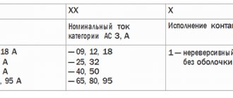
Starter modifications are indicated by numbers that indicate:
the first is the size of the starter;
the second is the type of execution (1 – open, 2 – protected, 3 – dust and waterproof);
third - irreversible or reversible, the presence or absence of a thermal relay (1 - non-reversible without a thermal relay, 2 - non-reversible with a thermal relay, 3 - reversible without a thermal relay, 4 - reversible with a thermal relay).
In an example it looks like this:
PME-111 – magnetic starter of the first magnitude in an open design, irreversible, without a relay;
PA-423 – magnetic starter of the fourth magnitude, manufactured in a protected design, reversible, without a relay;
PA-312 is a magnetic starter of the third magnitude, manufactured in an open design, irreversible, with a thermal relay.
Since the 80s, PAE magnetic starters have been replaced with improved analogues of the PMA series.
The PMA and PML series of magnetic starters are designed for currents from 6.3 to 160A at voltages up to 660V. Installation of starters
This type is carried out to start high power asynchronous motors - up to 90 kW. They are equipped with three-pole electrical and thermal relays, which makes it possible to prevent overloads of unacceptable duration, including protection against two-phase operation. Magnetic starters of the PMA and PML series are produced in both open and protected versions, irreversible or reversible, with the ability to switch the connection diagram from star to delta. The switching wear resistance of these devices for category AC-3 is from 2 to 3 million VO cycles. Mechanical wear resistance – from 10 to 16 million VO cycles.
Thyristor starters are used to control three-phase electric motors located in stationary or mobile installations. Their power part is made of thyristors, which are connected in back-to-back parallel pairs for each phase. The starter should be installed in a vertical position, but deviations from vertical up to 45° in any direction are allowed. The starter can operate in both continuous and intermittent modes with a switching duration of 60% and a switching frequency of up to 600 times per hour. The devices have thermal protection against possible overloads, as well as maximum current protection, the operating threshold of which can be adjusted. The starter is controlled using buttons with or without latching the command. Control using contactless logic elements is also possible.
© All materials are protected by the Russian Federation copyright law and the Civil Code of the Russian Federation. Full copying is prohibited without permission from the resource administration. Partial copying is permitted with a direct link to the source. Author of the article: team of engineers from OJSC Energetik LTD
Source: energetik-ltd.ru
Briefly about the main thing
Magnetic starter is a switching device for controlling a power network. Namely, starting and stopping electric motors.
Magnetic starter device: three pairs of power contacts, a coil with a core to which an armature is connected. The latter is connected to a block of moving contacts.
The starter is connected via the start-stop button.
Although the starter performs the functions of a power network contactor, it is not a contactor, because it is very different from the latter in its design form and current rating.
Types of starters by purpose
Now I will give a couple of examples of starters - real circuits.
This starter circuit is assembled on three second-value contactors and is used to connect an electric motor according to a star-delta circuit. At the top left three phases are supplied, at the bottom three phases go to power the motor. Red wires – powering the contactor coils and checking operation. Protection (automatic motor) is not shown.
reversing starter with automatic motor
Here is a reversing starter, with two mutually interlocked contactors. Automatic engine protection motor - on the right.
How to connect a contactor
When connecting a contactor, you immediately need to decide on the mechanism that it will turn on. This could be a motor, pump, fan, heating elements, compressors, etc. The main feature of a contactor that distinguishes it from a machine is the absence of any protection. Therefore, when thinking through the circuits for switching on electrical equipment through a contactor, it is necessary to take into account the current-limiting and heating elements. To limit and shut down equipment in case of short circuits and loads many times higher than the rated load, fuses and circuit breakers are used. Thermal relays are used to prevent long-term slightly exceeding the rated currents of operating equipment.
In order to correctly connect a contactor to a circuit, you need to clearly understand which of the contacts are power and which of them are auxiliary, that is, block contacts. You also need to look at the ratings of the switching coil. The voltage, its type and magnitude, as well as the currents that flow through it for normal operation must be indicated there. During operation, power contacts may burn, so they must be inspected and cleaned regularly.
How to connect a modular contactor
A modular contactor is a type of conventional switching devices of the same type, only they are mainly used for switching switchboards on and off remotely. That is, turning it on, power is supplied to a group of machines, each of which is responsible for its own specific circuit. It is installed on a DIN rail. Can switch both direct and alternating current circuits.
Connecting a contactor via a button
To connect the contactor via a button, you need to study the attached diagram below. It is designed to start a load, in this case a motor, from a contactor whose coil is designed for 220 Volts alternating voltage. Depending on the voltage, it is worth considering its power supply. Therefore, when purchasing and selecting a contactor, it is worth taking this nuance into account. Since if the electromagnet is designed for constant voltage, then such a source will be needed.
When you press the start button, the contactor electromagnet coil will receive power and it will turn on. The power contacts will close, thereby supplying voltage to the asynchronous motor. The block contact of contactor K1, which is connected in parallel to the stop button, will also close. It is called by electricians a self-retaining contact, since it is this that supplies power to the switching coil after the start button is released. When you press the stop button, the power from the electromagnet is turned off, the power elements of the contactor break the circuit and the engine turns off.
Connecting a contactor with a thermal relay
The thermal relay is designed to prevent prolonged minor current overloads during operation of electrical equipment, because overheating negatively affects the condition of the insulation. Frequent excesses of temperature and current will lead to its destruction, and therefore to a short circuit and failure of an expensive actuator.
When the current in the stator circuit of the electric motor increases, the elements of the thermal relay KK will heat up. When the set temperature, which can be adjusted, is reached, the thermal relay will operate and its contacts will break the circuit of the electromagnet coil of the KM contactor.
For safety reasons, you must remember that work in the contactor circuit must be carried out when it is completely de-energized. In this case, the power supply must be locked with a key or prohibiting sign from unauthorized or erroneous activation. And also you cannot turn on this device with the arc chutes removed, this will lead to a short circuit.
Classification and main characteristics of magnetic starters.
- The rated current of the main contacts is the current value for which the contactor is designed for an electric motor operating in AC3 operating mode. That is, we need a starter for a 7.5 kW electric motor with a voltage of 380V, contactors of the second value are selected. If this electric motor operates in the AC4 operating mode, which is characterized by frequent starts and stops, prolonged starts under load, then it is recommended to use a starter of a larger value.
- Rated voltage – the voltage value for which the body of the electromagnetic starter is designed.
- Control coil voltage – the magnitude and type of control voltage of the coil.
- The wear resistance class of the starter is the number of operation cycles guaranteed by the manufacturer in AC3 operating mode. At the moment, most imported starters are produced with wear resistance class A, while domestic ones produce KMD contactors (analogous to PM 12) with wear resistance class A
- PM12 KZEA produces by default wear resistance class B.
- PML starters produced by NPO Etal OJSC are manufactured with wear resistance class B.
- IP00 – the device is not protected from dust and moisture
Star-delta starters ensure the switching on of electric motors by turning on the power according to the star circuit, with a transition to a delta, which reduces inrush currents and protects electrical equipment and cables from high inrush currents. Provides energy savings when engines are turned on frequently
Source: www.elektro-portal.com
What is the difference between a contactor and a starter?
In industry, commercial and civil engineering, any tasks related to starting and stopping motors equipped with remote control are solved by contactors and starters. These devices are used where frequent starts or switching of electrical equipment with high load currents are constantly required. Let's look at what these devices are and how they differ from each other.
What is a contactor and starter
Contactor
- this is an actuator, which is a block of high-speed switches (i.e. contact groups). It can be a stand-alone device or part of other equipment. A contactor is a remotely controlled switching device, which is designed for frequent switching of electrical circuits under nominal (normal) operating modes. The closing or opening of contacts is usually carried out using an electromagnetic drive. A distinctive feature of contactors, in comparison with electromagnetic relays that perform approximately the same functions, is that they break the electrical circuit simultaneously in several places, while electromagnetic relays usually break the circuit only at one point.
Starter (magnetic)
- this is a modified contactor that has additional equipment (usually a thermal relay, fuses, an additional contact group or an automatic machine for starting an electric motor).
Difference between contactor and starter
There are three types of contactors: alternating current, direct current, and sometimes direct-alternating current.
Direct current devices are used to turn on and off power receivers in direct current electrical circuits in automatic restart devices and in drives of high-voltage switches. This equipment (single-pole and double-pole devices) is designed to operate with voltages from 22 to 440 V and currents up to 630 A.
DC contactor MK 2-20B-U3 63A
AC devices are used to turn on starting resistors, heating devices, to control a three-phase asynchronous electric motor with a squirrel-cage rotor, to start three-phase transformers, braking electromagnets, etc. AC devices are designed for switching AC electrical circuits.
Magnetic starters are usually used for remote control of asynchronous three-phase electric motors with a squirrel-cage rotor. An electromagnetic starter is a combined electromechanical control and distribution device designed to start and accelerate to the rated speed of the motor, as well as to ensure its uninterrupted operation, protect the connected circuits and the electric motor from operating overloads and power outages. Magnetic starters equipped with surge suppressors are used in control systems using microprocessor technology. Starters operate with alternating voltage from 24 to 660 Volts and a frequency of 50-60 Hertz or with constant voltage from 34 to 440 V.
Purpose and device
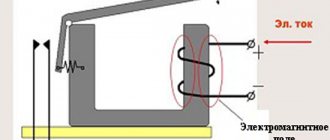
Magnetic starters are built into electrical circuits for remote starting, stopping and providing protection for electrical equipment and electric motors. The operation is based on the use of the principle of electromagnetic induction.
The basis of the design is a thermal relay and a contactor combined into one device. Such a device can also operate in a three-phase network.
Such devices are gradually being replaced from the market by contactors. In terms of their design and technical characteristics, they are no different from starters, and they can only be distinguished by their name.
They differ from each other in the supply voltage of the magnetic coil. It comes in 24, 36, 42, 110, 220, 380 W AC. The devices are produced with a coil for direct current. Their use in an alternating current network is also possible, for which a rectifier is needed.
The starter design is usually divided into upper and lower parts. In the upper part there is a movable contact system combined with an arc extinguishing chamber. Also located here is the moving part of the electromagnet, mechanically connected to the power contacts. All this makes up a moving contact circuit.
At the bottom there is a coil, the second half of the electromagnet and a return spring. The return spring returns the upper half to its original state after de-energizing the coil. This is how the starter contacts break.
Contactors are:
- Normally closed. The contacts are closed and power is supplied constantly; shutdown occurs only after the starter is triggered.
- Normally open. The contacts are closed and power is supplied while the starter is running.
The second option is the most common.
Types of three-position switches
Three position packet switch
Electrical switches with 3 positions are available in various designs. Some models are equipped with the option of fixing the switch position. They are equipped with a key locking mechanism that prevents spontaneous transition to another position. Others that do not have this function return to their original position on their own. The design of some devices provides for a zero position - it involves disconnecting all contacts.
Typically, products are manufactured with the expectation of operation in electrical networks with a nominal current of 25, 16 or 10 A. As for voltage, for direct current its value can reach 220 V, for alternating current - up to 500. The devices are equipped with markings indicating the power level and protection category.
The most common design option is a 3-position mechanical packet switch. Their control element is not a button, but a handle. Modern models are equipped with ergonomic handles, the design of which prevents fingers from slipping. There are two types of products - biscuits and cams.
The biscuit switch device includes plastic plates (bags) with contact pins rigidly fixed to them. Between the latter there are fiber washers for extinguishing sparks, which, together with a double break in the electric arc, make it possible to switch high currents. There is also a moving contact connected to the switching mechanism. Its position is set by turning the shaft, which is provided by a handle and a special spring, which allows you to instantly open and close the contacts. The shaft has 3 set positions, each of which corresponds to a certain configuration of clamped or open pairs of contacts. Such a device can be used, among other things, to connect a three-phase electric motor with a reverse option - rotation of the rotor in a direction other than normal.
Operation of automatic three-phase switch
The cam device also includes a series of packages, but arranged differently. On the outer sides of the plates connecting to the body there are moving contacts, and on the inner sides there are static ones. The first of them look like bridges with springs. Their position is regulated by a rod mechanism that changes position under the action of a cam. The latter, in turn, changes its position through the handle and shaft. Both in the case of biscuit models, and in devices with cams, the shaft can have a different number of positions (up to eight). In three-position devices their number is three.
The switch can be mounted on a DIN rail, on a wall, or in a cabinet, depending on the model. Explosion-proof products are produced for use in industries that pose a danger to human health. Most three-position switches, however, are susceptible to explosions, temperature changes, and do not tolerate moisture. The degree of sensitivity of the device to environmental conditions can be determined by its appearance: if the product is open and lacks a protective casing, it is highly sensitive; it should only be installed inside a switchboard in a room with dry air. Switches with a plastic or metal housing and contact-protected clamps can also be installed outside the switchboard.
The advantages of the devices include reliable operation, resistance to wear and tear, and a fairly low price. They suppress electrical arcs very quickly, but can withstand a limited number of switching overloads. A weakness of these products compared to circuit breakers is also their limited capabilities as a protective device: they do not protect against short-circuit incidents. Also, mechanical switches cannot be repaired: if the product becomes unusable, it is dismantled and subsequently disposed of, and a new one is installed in its place. They fail relatively quickly, although some manufacturers claim that the device can withstand up to half a million switchings.
What is a magnetic starter?
Magnetic starters are also switching devices, which are actually modified contactors that support the ability to switch high-power AC and DC loads. These devices are effectively used to turn on/off power electrical circuits. The proposed switching systems have a fairly wide range of applications. Their main purpose is to start, reverse current and stop a 3-phase electric asynchronous drive. In addition, these devices can be successfully used in remote control systems for various electrified objects. In addition to the main working elements, contactors can be equipped with various additional components such as thermal relays, auxiliary contact groups, automatic motor starters, etc.
What do a contactor and a starter have in common?
To understand what the differences are between these two switching systems, let’s first understand how they are similar to each other.
What a starter and a contactor have in common is that both of these devices are used to switch electrical circuits that power electrical equipment. Both contactors and starters are used to start/stop AC motors, as well as to input or output resistance stages if the starting/stopping is performed according to the rheostat principle.
Both the contactor and the starter have in their design additional pairs of contacts used for control circuits. They can be normally closed or normally open pairs of contacts.
Dimensions.
A contactor, unlike a starter, is a rather weighty and large-sized device. For example, a 100-amp contactor, compared to the same starter, is several times heavier and has significantly larger dimensions.
Design features
If we consider the design of the contactor, then powerful power contactors with arc-extinguishing chambers immediately catch the eye. There is no protective casing as such in contactors; the contactor is mounted on special panels located in enclosed spaces.
As for the starter, its power contacts are always protected by a plastic case. There are no large arc extinguishing chambers in the starters, so they are not recommended for use in powerful electrical circuits where frequent switching is required.
Security
Thanks to the use of a plastic housing in the starter, and in some cases a metal casing, these devices are characterized by a high degree of protection from external factors. Therefore, such starters can be installed even outdoors, which cannot be done with contactors.
Purpose of devices
The main purpose of the starter is to start and stop 3-phase electric drives operating on alternating current. In addition, these devices can switch circuits to supply power to lighting systems, heating equipment and other electrical equipment.
As for the contactor, it is suitable for switching any DC and AC circuits.
Conclusion
Based on the above, it follows that the starter is a kind of modification of the contactor and can be used for certain purposes. Contactors, the design of which is constantly modified, can be used in almost any case to perform switching of electrical circuits. Therefore, in the modern consumer market, contactors have practically replaced starters and successfully perform their functions.
Difference between contactor and starter
- What do the devices have in common?
- Differences between devices
- Bottom line
What do the devices have in common?
The contactor, however, like the magnetic starter, is “engaged” in switching circuits, mainly power ones. Thus, the use of both devices is advisable when starting AC motors or when inputting/outputting resistance stages in the case of rheostat starting.
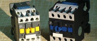
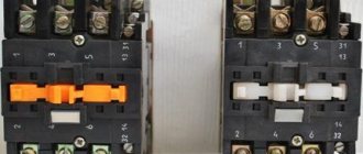
The design of the devices can be represented by one or more pairs of contacts for the control circuit - normally closed or open. By the way, visually they may not even be distinguishable in some cases, as you can see by looking at the photo:
Although power contactors can vary significantly, like this one:
Differences between devices
It is common for a large number of commercial enterprises to call a magnetic starter a “small-sized contactor”. After all, if you compare a contactor with it, similar in current load, then the difference between their dimensions will be visible to the naked eye. In addition, the weight of a three-pole 100-amp contactor is quite high compared to a 100-amp starter.
It should be borne in mind that it will not be possible to acquire a low-current contactor (for example, a 10-amp one) - they simply are not produced. Only a magnetic starter can become a link in weak chains.
Differences between devices can also be found in their design features. The contactor has a pair of power contacts and rather bulky arc extinguishing grids. Thus, the device does not have its own body, which requires its installation in places where it will be inaccessible to unauthorized persons and limited from moisture.
The magnetic starter is distinguished by the fact that the outside is covered with a plastic “shell” that provides protection to the power wire contacts. At the same time, the device does not have arc chutes, which is also a difference. Therefore, it is not used for installation in high-power circuits with a large number of switchings due to insufficient protection against arc discharges.
At the same time, the starter differs from its “competitor” by providing better protection for electrical equipment, especially if there is an additional casing (in particular metal). This makes it possible to install the device almost anywhere, which, in turn, a contactor cannot boast of.
The difference between electrical devices is also due to their purpose. Despite the fact that the magnetic starter is well suited for heaters, solenoid coils, lamps of various power levels and other electrical receivers, in fact, it is intended for asynchronous 3-phase AC motors.
In this regard, the design of each is represented by 3 paired power wires. Its control contacts have to “deal with” maintaining the device’s on state or, for example, creating complex control circuits with reverse starting.
The contactor is different in that it switches absolutely all alternating current circuits. Hence the differences between devices in power wires - contactors are “distinguished” by the presence of 2 to 4 poles.
In fact, we can say that the differences between the devices are quite arbitrary. In practice, the difference between them is determined by the purpose of the device and the pricing policy. In any case, the consumer will be able to choose a product in accordance with his needs and requirements, and the difference in name is determined by the manufacturers. We hope we helped you answer the question of how a contactor differs from a magnetic starter!
Finally, we recommend watching a useful video on the topic:
Related materials:
Actions when operating contactors and magnetic starters
When connecting and operating these types of devices, to ensure safety and proper functioning, a number of rules must be observed:
- Before installing the device, it is necessary to remove the lubricant layer from the working surfaces and check how correctly the devices are adjusted. It is also necessary to examine the condition of electrical connections.
- From time to time it is necessary to check the condition of the contact group. This must be done every time after turning off the electric current in emergency mode, as well as after 50 thousand operations.
- When cleaning the surface of the contacts, care must be taken not to deform them. The position of the breaking contacts in relation to each other is also checked.
- For multi-pole contactors, parallel closure is tested for all available poles.
- Check the gap between the contacts. Replacement is carried out at a reduction of half (in the presence of overlays - by 80%).
Both groups of devices have certain restrictions regarding operating conditions and scope of application. For correct operation of the circuit, you need to select a device that is relevant to the current conditions.
Differences between a contactor and a magnetic starter
Starters are used for switching low voltage circuits. The products also differ in their dimensions: the contactor is larger than the starter.
The next difference lies in the design: contactors have powerful power contacts and are equipped with arc arresters. Starters do not have arc chutes, and the power contacts are much weaker. The devices also differ in their purpose: magnetic starters are used in general to supply electrical power to devices (lamps, electrical receivers), and contactors are intended for switching absolutely any power circuit.
What is a contactor and why is it needed?
In electrical networks, you constantly have to turn on or off various loads or control their operation. As we know, in everyday life there are mechanical switches and switches for these purposes. But such devices have a very limited durability, and for large electrical systems, control using mechanical switches is an inconvenient and ineffective way. That is why a device was created that has a huge service life, allows you to perform on and off cycles up to several thousand times per hour, and most importantly, makes it possible to control the load remotely. In simple words, this is a switch.
Electromagnetic contactors are used in all areas of our lives. They turn on street lighting, control the shutdown of high-voltage power lines, lines of transport systems (tram, trolleybus, railway), and are widely used in construction and industry to start powerful power plants, engines, machines and other equipment.
Moreover, such switching devices are also used in residential buildings for various purposes, such as, for example, turning on electric heating devices or water heaters, to control ventilation units, water supply or sewage pumps. Progress does not stand still, and at the moment, smart home systems controlled by contactors or groups of such devices are gradually entering the lives of ordinary people.
These devices play a huge role in electrical safety and, as a result, preventing fires from ignition of electrical equipment or power lines.
These devices have a number of advantages over various modular devices:
- Can connect to any network;
- They have compact dimensions;
- Absolutely silent in operation;
- Can be used at high powers and high currents;
- Easy to operate and easy to install;
- Can work in any conditions.
Design and principle of operation of the contactor
Based on the name, this is a group of contacts designed to connect electrical lines. The main application is a modular contactor that switches power lines. If in a regular switch (even an automatic protective one), closing and opening occurs manually, AC contactors are controlled remotely.
Let's consider the circuit of a simple contactor, without interlocks and protective modules.
For those who are more or less familiar with electrical engineering, it is not difficult to understand the principle of operation. The basis of the power group is the contacts indicated in the diagram by the letters “L” and “T”. Depending on the design, the system may simultaneously include one, two, or more pairs of contacts. In order for the connecting conductor strip to press against the fixed contacts, force is required. In conventional switches, this is a mechanical device driven by the operator. Our circuit is triggered by an electromagnet. When control voltage is applied to coil A1-A2, the solenoid is retracted and the power (operating) contacts are closed.
After removing power from the control winding, the return spring instantly removes the contact strip from the power terminals.
What is inside
Despite the apparent complexity and cumbersomeness of the design, the element base is simple:
- contact group made of copper (brass) alloys, designed for a certain resource;
- “T” shaped contact strip directly connected to the electromagnet solenoid;
- an electromagnet coil made for a specific contactor model;
- dielectric housing, which performs not only protective, but also load-bearing functions;
- arc extinguishing elements that are installed in the switching mechanisms of electrical installations with high current consumption.
In fact, the design is not much different from a conventional relay. There are also normally closed, normally open, and switching circuits (in which both types of contact groups are present). At the same time, according to the technical requirements of GOST, the modular contactor must have only one rest position (the state of the contact group in the absence of external control pressure).
When mechanical action is applied to a conductive strip (or group of strips), one or more contact pairs are closed (opened).
Thus, with the help of direct or remote influence, it is possible to control the power of electrical installations or power lines.
Contactor IEK
With the IEK contactor everything is much simpler. Its marking is based on almost the same principle.
Alphanumeric designation of working terminals:
L1-L2-L3 (1-3-5)
T1-T2-T3 (2-4-6)
Double marking of auxiliary contacts: 13-14
first group (first numbers 1-1)
with normally open contact (second digits 3-4)
For the Russian market there may be an abbreviation “NO” - normally open.
The coil voltage of 230V (50Hz) is written on the side. And other technical parameters.
KMI – 10910 – its order number
AC-3 In=9A and AC1 In=25A – possible connected load for various categories.
The power of the connected load is also indicated depending on their supply voltage.
Even a schematic diagram of a contactor with all its contacts (working and auxiliary) can be depicted.
Below is written the regulatory document to which this product corresponds - GOST R50030.4.1
Characteristics and types of starters by characteristics
Before choosing a contactor, you need to decide on the load, and make the choice based primarily on the load power. The parameters of contactors can be clarified on the manufacturers’ websites or from trading organizations, but here we will present and consider the most important ones. The main parameters (current, load power) are usually indicated on the starter housing.
Size (conditional dimensions) of the starter (contactor)
The most important parameter, the value characterizes the power and dimensions of the starter. There are the following starter sizes:
- zero value – for a maximum current of up to 6 A (through each working contact)
- the first - for a maximum current of up to 9 - 18 A (depending on the design of the contacts)
- starter 2 sizes – up to 25 – 32 A
- starter 3 sizes – up to 40 – 50 A
- starter 4 sizes – up to 65 – 95 A
- 5th size starter – up to 100 – 160 A
- sixth value – from 160 A and above
This means the current for application category AC-3 (for an inductive load), for category AC-1 (resistive or low-inductive load - for example, heating elements) the maximum current for the same starter will be one and a half to two times higher. The size of the starter determines how much power it can switch (three-phase circuit 380 V, inductive load).
- 1 – up to 2.2 – 7.5 kW
- 2 – up to 11 – 15 kW
- 3 – up to 18 – 22 kW
- 4 – up to 30 – 45 kW
Principle of operation
Unlike switching contact units, contactors can only carry nominal currents, since they are not intended to interrupt a circuit (for example: a short circuit).
Using an additional current circuit, the device is controlled, passing through an inductive coil with a voltage from 24 to 220-380 volts. In order to increase safety during product operation, the total current value should be slightly lower than the operating current level in the passing circuits. The contactor does not have the mechanical resource to hold the contacts in the active position, therefore, in the absence of a guiding voltage flow on the inductive coil, it opens the circuit. To hold the circuit in the active position, an “auto-catch” system is used using two open contacts (example: using a programmable logic controller).
Contactor circuit
up to 650-660 V