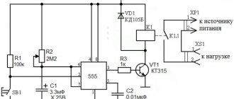
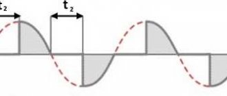
In this tutorial I will show you how to create a simple PWM (Pulse Width Modulation) controller from a 555 chip, a timer and some other components. It's very simple and the NE555's circuitry works well for controlling LEDs, light bulbs, servo motors or DC motors.
My 555 PWM controller can only change the duty cycle from 10% to 90%.
Main parameters of the 555 series IC
The NE555 internals includes five functional units, which can be seen in the logic diagram.
At the input there is a resistive voltage divider, which generates two reference voltages for precision comparators. The output contacts of the comparators go to the next block - an RS flip-flop with an external reset pin, and then to a power amplifier. The last node is an open collector transistor, which can perform several functions, depending on the task at hand.
The recommended supply voltage for IC types NA, NE, SA is in the range from 4.5 to 16 volts, and for SE it can reach 18V. In this case, the current consumption at minimum Upit is 2–5 mA, at maximum Upit – 10–15 mA. Some 555 CMOS series ICs consume less than 1 mA. The highest output current of an imported microcircuit can reach a value of 200 mA. For KR1006VI1 it is not higher than 100 mA.
The build quality and manufacturer greatly influence the operating conditions of the timer. For example, the operating temperature range of NE555 is from 0 to 70°C, and SE555 from -55 to +125°C, which is important to know when designing devices for operation in open environments. You can get acquainted with the electrical parameters in more detail and find out the typical values of voltage and current at the CONT, RESET, THRES, and TRIG inputs in the datasheet on the XX555 series IC.
Advantages and disadvantages
The main advantage of a time relay on a 555 chip is its low price and a huge number of electrical equipment circuits developed and using it.
There are also shortcomings, which, however, have been corrected in the release of microcircuits with a transistor base based on CMOS. When using bipolar ones, at the moment the state of the generating cascade changes to the opposite, a parasitic voltage of up to 400 mA could arise at the terminals. The problem is solved by installing a 0.1 µF polar capacitor between the control contact and the common wire.
Capacitor that reduces the influence of interference on the device
You can also improve the noise immunity of the timer chip. To do this, place a 1 µF non-polar capacitor on the power supply line.
Areas of use
It is difficult to find directions in the development of electrical appliances in which the NE/SE 555 timer would not be used. It is used to successfully design generator boards and time relays, with the ability to control intervals from microseconds to several hours, and is used to create light sensors and control liquid levels, security alarms and combination locks.
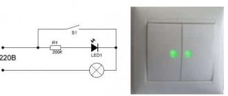
Dark alarm
Everyone, willingly or unwillingly, encounters devices every day that turn on or off when the intensity of the luminous flux (illuminance) changes:
- on the streets, lighting lamps are turned on using such devices;
- in the entrances - emergency lighting of staircase landings;
- in apartments there are various devices that have a daily rhythm of operation.
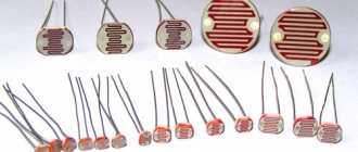
The principle of operation of the device, which responds to changes in illumination, is based on the fact that when the resistance of the photoresistor changes, the potential at the NE555 input changes. This causes a change in the output voltage and turns on the relay.
Alarm module
An alarm system assembled using a 555 microcircuit uses it as a one-shot device, which, upon receiving a signal from the sensor, generates a control signal that turns on the siren. The duration, tone and volume of the sound are regulated by variable resistors introduced into the circuit.
Metronome
An analogue of a mechanical device that sets the rhythm of a certain frequency and is used by musicians in the process of training and rehearsals has an electronic analogue, assembled using a 555 timer.
In this case, the microcircuit operates in multivibrator mode, generating periodic pulses, which are regulated by transistors Q1 and Q2, which provide adjustment of the pulse frequency. The pulse frequency is directly regulated by potentiometer P1. To obtain a click similar to the click of a mechanical metronome, transistor Q3 is added to the circuit.
Timer
An example of using a microcircuit for its “direct” purpose – counting a time interval. The operation of the device is based on the ability to switch modes, issuing signals to turn on/off.
When the capacitor is discharged, the potential at the 555 input is zeroed. During the charging process, which requires a certain time, a specified interval is “counted down”. After reaching the specified charging value, the capacitor is discharged and the potential changes. The timer is triggered to turn on or off.
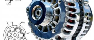
Accurate Generator
Used to regulate the parameters of output pulses in various electronic devices. In particular, in high-frequency converters included in the power supplies of LED strips.
Location and assignment of pins
The NE555 chip has eight outputs. Currently, microcircuits are found in rectangular DIP packages, although, occasionally, you can find a microcircuit in a round metal case. This does not change the purpose of the pins.
The location and numbering is shown in the figure:
12V screwdriver speed controller diagram
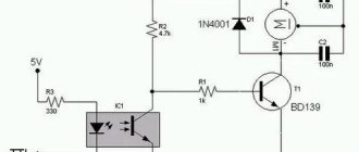
The 555 timer is widely used in control devices, for example, in PWM speed controllers for DC motors.
Anyone who has ever used a cordless screwdriver has probably heard a squeaking sound coming from inside. This is the whistling of the motor windings under the influence of the pulse voltage generated by the PWM system.
It is simply indecent to regulate the speed of an engine connected to a battery in another way, although it is quite possible. For example, simply connect a powerful rheostat in series with the motor, or use an adjustable linear voltage regulator with a large radiator.
Location and assignment of pins
The NE555 and its analogs are primarily available in eight-pin PDIP8, TSSOP, or SOIC packages. The pinout arrangement, regardless of the housing, is standard. The symbolic graphic designation of the timer is a rectangle with the inscription G1 (for a single pulse generator) and GN (for multivibrators).
- General (GND). The first conclusion is regarding the key. Connects to the negative power supply of the device.
- Trigger (TRIG). Applying a low-level pulse to the input of the second comparator leads to the launch and appearance at the output of a high-level signal, the duration of which depends on the rating of the external elements R and C. Possible variations of the input signal are written in the “Montistrator” section.
- Output (OUT). The high level of the output signal is (Upit-1.5V), and the low level is about 0.25V. Switching takes about 0.1 µs.
- Reset (RESET). This input has the highest priority and is able to control the operation of the timer regardless of the voltage on the other pins. To allow startup, it is necessary that a potential of more than 0.7 volts be present on it. For this reason, it is connected through a resistor to the power supply of the circuit. The appearance of a pulse of less than 0.7 volts prohibits the operation of NE555.
- Control (CTRL). As can be seen from the internal structure of the IC, it is directly connected to the voltage divider and, in the absence of external influence, produces 2/3 Upit. By applying a control signal to CTRL, a modulated signal can be obtained at the output. In simple circuits it is connected to an external capacitor.
- Stop (THR). It is the input of the first comparator, the appearance of a voltage on which exceeds 2/3 Upit stops the operation of the trigger and turns the timer output to a low level. In this case, there should be no trigger signal at pin 2, since TRIG has priority over THR (except for KR1006VI1).
- Discharge (DIS). Connected directly to the internal transistor, which is connected according to a common collector circuit. Typically, a timing capacitor is connected to the collector-emitter junction, which discharges while the transistor is in the open state. Less commonly used to increase the load capacity of the timer.
- Power (VCC). Connects to the positive of a 4.5–16V power source.
Main characteristics of the NE555 chip
The characteristics of the timer from different manufacturers may differ within small limits, but no one has any fundamental deviations (except for microcircuits of unknown origin, you can expect anything from them):
- The supply voltage is usually indicated from +5 to +15 V, although datasheets contain limits of 4.5...18 V.
- The output current is 200 mA.
- Output voltage - maximum VCC minus 1.6 V, but not less than 2 V with a supply voltage of 5 V.
- Current consumption at 5 V is no more than 5 mA, at 15 V – up to 13 mA.
- The error in forming the pulse duration is no more than 2.25%.
- The maximum operating frequency is 500 kHz.
All parameters are specified for an ambient temperature of +25 °C.