Inexperienced radio amateurs sometimes face the problem of replacing microcircuits on a printed circuit board. When carrying out a seemingly simple process of dismantling radio components, detachment of contact pads or damage to a serviceable element often occurs due to overheating of its housing. This problem arises due to the need to heat a large number of legs at the same time or remove solder from the contacts one by one, which leads to their breakage.
Therefore, for high-quality dismantling, you need to thoroughly study the question of how to desolder microcircuits, as well as which soldering iron to choose for removing radio components from a printed circuit board.
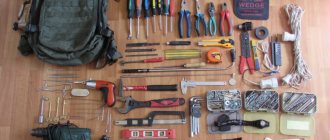
Dismantling needles
Here they threw a set of dismantling needles on Ali. More precisely, tubes. Well, remember this old-fashioned method of desoldering microcircuits? You warm the pad, put a syringe needle on the pad, it separates the pad and the leg, the solder does not stick to it, so it is easily removed. Here is the same thing, only in different diameters and on a comfortable handle. The price is about one hundred rubles, and even with free delivery. Those. freebie finally.
The stings are in a plastic box, very good quality. They don’t hang out, they don’t fly out. The box snaps shut.
- 0.8
- 1.0
- 1.2
- 1.4
- 1.6
- 1.8
- 2.0
- And some kind of 1.2mm awl. Why is it there I don’t understand.
The steel is durable. I soldered a lot of things with them, not a single tube broke.
The thinnest one bent once, pressed hard and it folded 90 degrees. It bent and didn't even crack.
The main drawback of this set is that there is no 0.9mm needle. I have often encountered the problem that a 0.8 needle does not include a component, and a 1.0 needle does not fit into the board hole, and here 0.9 would be ideal. But she is not there, alas. In general, the most popular needles are 0.8, 1.0 and 1.5mm. The rest were rarely useful.
I bought it on Aliexpress, here
. It took about a month.
Well, I made a movie:
Thank you. You are amazing! In just a month, we raised the required amount of 500,000 for a hockey rink for the Aistenok orphanage. Of which 125,000+ were from you, EasyElectronics readers. There were even transfers for 25,000+ and just a flow of payments for 251 rubles. This is incredibly cool. The contract is now being concluded and preparations for construction are underway!
And I was stuck for at least three years of monthly work on articles :)))))))))))) Thank you for such a powerful kick.
Soldering with liquid or paste fluxes
The advantage of such compounds is that they can be pre-applied to the connection point. That is, the flux begins to work even before heating. When touched with a soldering iron, the second stage of the reaction occurs, and the liquid flux serves as a lubricant for the spreading of solder.
Another plus is that a paste or liquid cleaner increases the contact patch. The main problem with soldering non-flat objects is that the heat transfer area from the soldering iron is minimal. If the point of contact is moistened with flux, the temperature is transmitted more efficiently.
The only drawback: there is no mechanical impact on the surface.
Information: some old-school professionals dissolve pine rosin with alcohol or a more liquid flux, and an effective composition is obtained with virtually no drawbacks.
Soldering the microcircuits
Soldering the IC with a needle
Everyone solves this problem in their own way based on their experience and capabilities. But even having the opportunity to use a soldering station with a hair dryer, some still use this method. Me too. Therefore, in this article I decided to write how to desolder a microcircuit from a board using a needle from a syringe that I still use.
You can desolder the IC in several ways:
- using suction;
- soldering iron with nozzles;
- soldering iron using tubes;
- hair dryer (more suitable for desoldering large surface-mount ICs with planar leads).
Some will say that this is the last century and it’s time to switch to more modern methods, but I like it because it allows you to desolder the microcircuit with a soldering iron, quickly and accurately. Whether this is right or wrong is up to you to decide for yourself. Of course, it is not suitable for all cases, for example, in order to desolder an SMD chip, you need a different technology.
Syringe needle
You don’t need to dream of any new devices or expensive soldering irons to solder radio components; this is the cheapest and most practical way that allows you to solder a microcircuit with a regular soldering iron at home using an ordinary needle from a syringe, which, if not lying around in the medicine cabinet, is easy available.
There are several advantages here:
- the microcircuit does not overheat;
- the paths do not deteriorate;
- neighboring radio components do not heat up;
- accessibility and simplicity;
- cheapness.
Classification of soldering irons by power
The power of a soldering iron is its main characteristic, which significantly affects the quality of the work. The heating temperature of the soldering iron tip directly depends on the value of this parameter.
By power, soldering irons can be divided into the following groups:
- Soldering irons with a power of up to 10 W are used to work with thin conductors and small radio components.
- Soldering parts on printed circuit boards is most efficiently done with soldering irons with a power of 15-30 W.
- Soldering irons 40-60 W are most often used for work at home.
- Electrical wires of large cross-section are connected by devices with a power of 80-100 W.
- Soldering irons with a power of 200 W are designed for soldering metal structures using soldering acid.
There are several methods for desoldering microcircuits from a printed circuit board, which have their own advantages and disadvantages. The radio amateur himself must decide which method to use in a particular situation, based on his experience and the technical capabilities of the equipment.
How to desolder radio components from a board with your own hands - we explain in order
When some equipment breaks down, it is not at all necessary to immediately throw it in the trash. If you are interested in electronics and radio engineering, it would be wiser to solder the working elements of the microcircuit. Suddenly, in the future you will need a capacitor, transistor or resistor if you decide to make a homemade electronic product. In this article we will tell you how to desolder radio components from the board so as not to damage anything.
Principles of safe work with semiconductor radio components
Temperature conditions
All electronic devices are designed to operate at normal temperatures. They cannot withstand overheating for a long time and do not respond well to pulsed temperature influences: the semiconductor junction fails, contacts are broken, and the housing of the radio component is depressurized.
However, the main methods of their installation remain welding or soldering, which ensures the heating of the contact pads and their connection when cooling.
The brands of low-melting solders used, such as POS-60 or POS-40, begin to transform into a liquid state when heated to 183 degrees, and when cooled in air, they quickly cool down and create reliable contact.
The safety of the transistor, diode, microcircuit, capacitor is ensured due to the short time of melting and hardening of the solder on the leg of the radio component.
Board design
To ensure safe soldering, you should imagine the design of the board on which the radio component is attached. In practice, the most common models are with:
- one;
- or two layers of copper foil conductors onto which solder is applied.
They are glued onto dielectric plates made of fiberglass or getinax.
In addition to these models, special high-precision electronic devices use multilayer boards with a complex arrangement of conductive paths of various designs.
Installation of parts on them by soldering, using solder, is carried out by robots in a factory environment.
It is quite difficult for a home handyman to perform such work efficiently at home.
What do you need for this?
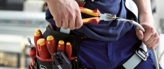
There are many devices for soldering parts. Of course, a radio amateur cannot do without a soldering iron, which will be the main assistant in this matter. However, in addition to the soldering iron, in order to desolder the element, you will need:
- Tweezers. To remove heated radio components. Instead of tweezers, you can use an alligator clip (shown in the photo below). The advantage of the clamp is that it will securely grip the part and also become a good heat sink.
- Hollow needles for dismantling. Buying them will not be a problem, the cost is low. Using needles, you can desolder a radio component quickly and accurately, which we will discuss below.
- Dismantling braid. It serves as a so-called sponge that absorbs molten solder into itself, thereby cleaning the board.
- Destination pump. The name speaks for itself. An indispensable item for frequent desoldering of radio components from boards at home.
You also need to prepare your workplace. It should be with good lighting. It is best if the lamp is located above the workplace so that the light falls vertically without creating shadows.
Application of copper braid
Before soldering microcircuits using this method, it is necessary to perform several preparatory operations. To do this, you need to carefully remove the shielding braid from a small piece of coaxial cable.
Next you need:
- clean and tin the soldering iron tip;
- moisten a piece of copper screen with flux;
- attach the braid to the contacts of the microcircuit;
- heat the protective screen with a soldering iron, the solder will saturate the braid and free the legs of the radio component.
The braid is a good heat dissipating element, which reduces the possibility of overheating of the soldering area. In the retail chain you can purchase ready-made braid impregnated with rosin. But due to the considerable cost and high consumption of material, for one-time work it is preferable to make it yourself.
Chip types
Currently, there are a number of cases, but only two are the most widespread, and in fact all other varieties are variants of two main types:
- DIP - roughly speaking, this version of the case is for internal mounting; the legs of this controller are placed in holes on the board;
- SMD – this type of microchip is designed for surface mounting; in this case, “spots” are placed on the board, to which the legs of the microcircuit are soldered.
Each option has its own advantages and disadvantages. But within the framework of the article, their features in terms of wiring are interesting. We’ll look at how to unsolder a microcircuit in a particular case a little lower.
How to safely unsolder a transistor, microcircuit, diode
Soldering conditions
When creating a workplace, you should pay special attention to its lighting. You cannot solder a radio component in semi-darkness. If your vision does not allow you to clearly see all the details, then you need to wear corrective glasses.
The electronic board must be clearly fixed in space, and the body must be in a stable position. It is best to work sitting or standing on both legs, holding the soldering iron confidently. After all, any wrong move will cause irreparable harm.
Technology for dismantling radio components
The tip of the soldering iron should be precisely placed on the layer of solder located in the socket of one leg of the transistor and quickly melt it.
Then a needle is inserted into this place from the reverse side and the tin is separated from the stem. If there is a dismantling braid or desoldering pump, then use them.
When the design of a radio component allows the use of a metal clamp to remove heat from the housing, then it must be used.
If the space for installing the soldering iron tip is very limited, then they work without using a heat remover.
In this case, special attention is paid to the length of time the radio component remains at elevated temperatures.
Features of dismantling microcircuits
The arrangement of the legs of the microcircuit strictly in a row allows you to melt the solder in all the sleeves of the contact pads of the board on one side of the case. This is a rather risky method, but in most cases with good skills it ends in success.
It is used when the tools described above for removing molten tin are not at hand, and the work needs to be done quickly.
Such operations are well provided by a transformer soldering iron with a tip made of copper wire, which can be bent to the shape of the legs of the microcircuit.
An awl or a thin screwdriver blade is placed under the microcircuit body. They act as a lever, move, and gradually pull out all the legs from their sockets at once at the moment the tin melts, but not before.
You should not try to completely remove the microcircuit in one go; it is enough to pull it out a little bit by bit on each side. At the same time, they monitor the temperature of the case and allow it to cool.
Using a similar method, I managed to remove the K554CA3 chip from the old board to work as a comparator in a homemade twilight switch.
Read also: Do-it-yourself machine for cutting plastic bottles
In old boards, the legs of radio components were often bent on the reverse side and soldered. They are more difficult to dismantle. You will have to melt the tin on each leg, put a needle on the bend and use it to align the contact wire so that it comes out normally through the sleeve hole.
I suggest you watch the video by the owner of Radioblogful “How to desolder a microcircuit in three different ways”
To resolve any questions, use the ability to comment on the article. Now you can share it with your friends via social networks.
When some equipment breaks down, it is not at all necessary to immediately throw it in the trash. If you are interested in electronics and radio engineering, it would be wiser to solder the working elements of the microcircuit. Suddenly, in the future you will need a capacitor, transistor or resistor if you decide to make a homemade electronic product. In this article we will tell you how to desolder radio components from the board so as not to damage anything.
Necessary tool
Soldering iron
Old models
A properly selected soldering iron can ensure normal heating of the contact tracks of boards and semiconductor leads.
The old EPSI model of the “Moment” type with a power of 65 watts has a universal design. It is not difficult to make it with your own hands.
Previously, resistive type models with a heating element made of thin nichrome wire were widely used.
Modern soldering irons
For specific soldering conditions, you can now purchase various types of models equipped with all sorts of functions.
For example, a soldering iron with tin suction has been specially designed for soldering microcircuits, transistors and diodes.
It quickly heats up a layer of solidified solder and easily removes it in a liquid state from the contact pad.
Radio component holders
When heating the transistor leg for tinning and soldering, you should always remove the heat from the body and semiconductor layer with some metal object.
For this purpose, tweezers or alligator clips are usually used. However, it is most convenient to work with a medical instrument with thin legs, which surgeons use during operations.
Fixing electronic boards
Radio components and boards are usually small in size and require reliable fixation in space. Soldering them while hanging is dangerous: a small wrong movement can damage the entire structure.
Soldering iron design
For long-term operation, a soldering iron must be light in weight, since a heavy device quickly loads the radio amateur’s hand, causing his movements to become inaccurate.
Structurally, the soldering iron consists of the following elements:
- The handle of the device can be plastic or wooden. Plastic handles can heat up significantly, so they are used in low-power soldering irons. Powerful devices are most often equipped with wooden holders.
- The nichrome heating element consists of mica, on top of which a spiral is wound. If the wire burns out, it is very difficult to replace it yourself. A soldering iron with a ceramic heater does not have this drawback, but is a very fragile device. If you avoid dropping the tool, the ceramic will last a very long time.
- The soldering iron tip is the main working surface. The tip is usually made of copper. If the tip burns, clean it with a finely cut file. There are soldering irons with replaceable tips.
Removing the DIP package
As already noted, this type of microcircuit is distinguished by its installation in holes on the circuit board. This imposes certain restrictions on the process of its dismantling. In order to carefully remove its legs from the holes, you need to remove the solder from the joint, almost completely freeing the legs. It should be noted that alternate heating and dismantling of a separate contact will not work here, since when it cools down, the remaining solder will again fix the microchip in place. Therefore, wiring DIP package is optimal using the following methods:
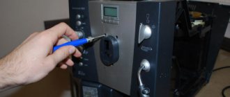
- Using improvised means - needles from medical syringes or special hollow tubes, now sold in electrical stores, are suitable for this purpose. But the option of using a medical needle is the cheapest and most accessible. To do this, you need to select a needle with a diameter slightly smaller than the mounting sockets for the microchip leg. Then cut off its pointed part with a file or simply bite it off, and then grind off the flattened part with a file. After this, installing the resulting hollow tube with an even cut on the mounting socket, simply heat it with a soldering iron, thereby freeing the chip leg;
- The second option is to drag the solder from the soldering site onto copper wires moistened with flux, such as alcohol rosin. A wire with flux heated by a soldering iron gradually draws the solder onto itself from the soldering site. This option takes longer, but is also quite effective;
- Using a soldering iron with solder suction - in this case, no particular difficulties in dismantling are expected. The main thing is to control the heating temperature in the contact area so as not to damage the board and the part itself.
These options will allow you to quickly and efficiently desolder DIP packages from the board.
Important! The main requirements for using a soldering iron in this case will be constant control over the pressure and temperature in the soldering zone. Overheating and excessive pressure can damage the part.
Important! When using a medical syringe needle, you can simplify the task of cutting it; to do this, before cutting, it is enough to red-hot the cut area.
Example of soldering for a soldering iron with a copper tip
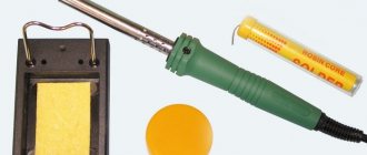
Any soldering begins with tinning pads, wires, and other elements that will need to be connected together. Tinning is actually a surface coating of surfaces with solder. The purpose of this procedure is simple. The surface layer will provide good cohesion for future welding solder, and therefore a reliable connection during soldering. Here it is necessary to say something about the materials that you are going to solder. So let’s say, it will be good to solder, ferrous metals are already worse, but I wouldn’t advise you to solder aluminum at all. Because this is a troublesome and thankless task. It is here that it is necessary to say that if you have a choice, then choose copper wires and connectors for soldering; this choice will allow you to solder comfortably. So, about tinning with a copper soldering iron. We heat up the soldering iron, usually this time is 5-7 minutes. Don't even try before. During heating, you can dip the soldering iron into rosin or solder fat once to prevent oxidation of copper.
As soon as the tip begins to confidently melt the solder, consider it warmed up.
During this time, you can still clean the wire or pad from insulation and oxide. If it is a stranded wire, then after removing the insulation, twist all the wires together. Also, if the connection is permanent, then also connect the wires of different conductors to each other. Now place the wire(s) on the platform and treat it with acid, rosin, or fat.
That is, with the reagents that I wrote to you about earlier. They are the ones who will contribute to tinning, and as a result, to the soldering itself. In our case, this is solder fat, I heated it and dipped the wire in it. Now we grab an excess portion of solder onto the tip, in fact it will be a drop of solder. We bring it to the conductor and move along it.
The conductor should be filled evenly.
Now it will look like something covered in a metal shell. If there is not enough solder, then again take the solder with a tip and distribute it at the soldering site.
We carry out the same procedure with the other conductor. Now you can solder the conductors together. We set them up the way we need them and each time, bringing a little solder on the tip of the pin, we fill the gap between the conductors.
If necessary, take solder and bring it to the soldering site.
The result is a beautiful, durable and reliable contact. If necessary, the conductors can be twisted before soldering.
We isolate the soldering area. Now about soldering to the board. Here again we need to start with tinning the board tracks. If you are mounting something on a universal circuit board, then immediately take a board with tinned contacts. Next, we straighten the contacts of the radio component and insert them into the holes so that they protrude from the other side by 0.5-1 mm. Now, as in the case of the wire, we take solder onto the tip and bring it to the leg-hole location.
We touch it, and the solder spreads along the leg, filling the hole. So we solder all the legs of the radio element (wires).
Now, although you haven’t learned how to solder with a soldering iron with a copper tip, you know how it’s done.
Maintenance (tinning) of a copper soldering iron tip during and after soldering
As I already told you, the copper tip fades over time and eventually changes its shape. As a result, it is necessary to put its shape in order from time to time. It is best to forge the tip, that is, use a hammer and anvil, and tap out the desired shapes. But if this is not the case, then you can get by with a simple needle file.
We take and process the sting so that it fits the shape (size) that is convenient for you. For me, this shape is the shape for a flat-head screwdriver. The two sides are ground off with a needle file, resulting in a smooth but “bare” metal – copper.
It must be said that copper is a soft metal. Handles it accordingly easily. After this shaping, it is necessary to protect the tip from oxidation. This is done simply by applying solder to the surface layer of the tip, which performs two functions. Firstly, we use it to solder, which we have already discussed. Secondly, it protects the tip from oxidation and burnout. So, when we processed the tip cold, we turn on the soldering iron. While it is warming up, but not yet warmed up, you can dip the tip in rosin or solder fat.
Then we take solder and apply it to the heated tip. The solder itself will spread over its surface. The entire tip is ready for use.
Restoration of the tip must be carried out periodically when you notice that the area on it has become uneven, and as a result, soldering has become inconvenient.
SMD controllers
Surface mounting of the housing makes it easier to dismantle. In this case, you can use a wide soldering iron tip and copper wire with flux and solder several contacts at once. But there are more interesting desoldering methods:
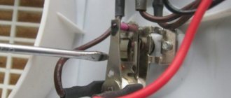
- Using a strip of metal or half a razor blade to distribute the heat of a soldering iron over one row of IC legs. In this case, a steel strip is installed on a row of contacts on one side and heated with a tip until the solder melts, after which this side is slightly raised above the board. Then the solder on the other side of the chip is melted in the same way;
- Using a long piece of copper braid with flux applied to it. The segment is placed on the legs of the microcircuit on one side and heated with a soldering iron; pulling the solder onto the braid, lift the part with tweezers. Then remove the solder from the other side of the controller in the same way;
- A technically interesting option is to use Rose or Wood alloys. Drops of this solder are applied to the contacts and heated, thereby reducing the melting point of the solder. Next, the solder gradually warms up, and the microcircuit is dismantled;
- Using a hair dryer or blowtorch. To use this tool, flux is applied to the soldering areas. After that, the surface and the part are heated, and the microcircuit is removed from the mounting spots with tweezers.
It should be noted that each dismantling option is used in specific conditions; the main task in this case is to select the most optimal option from a safety point of view and, when using it, not to damage the part itself or the board traces.
Important! When dismantling the microcircuit, it is important to remember that any parts or components on the board have their own temperature minimum; exceeding it will lead to the failure of the microcircuit.
Using improvised means and a soldering iron when installing or dismantling microcontrollers is quite justified, but requires at least skills in working with a soldering iron. If they are absent, you should first practice on unnecessary parts. This process will allow you to gain the necessary experience on how to unsolder a microchip without damage, and also choose the most optimal option for working with a specific board and type of chip case.
Desiccant pump: how to use it correctly
A vacuum desoldering pump is a very useful tool for soldering various radio components, be it microcircuits, a transistor, or, for example, a diode. Also, high-quality removal of tin from the contacts will help solder the working part without much difficulty.
The desoldering pump consists of:
- Vacuum flask, spout made of thermal material;
- Return spring;
- Piston.
Soldering radio components with a desoldering pump is quite simple. First of all, it is necessary to “cock” the destin pump. To do this, you need to fix it with a locking mechanism by pressing the piston (the fixation occurs automatically). Next, with a soldering iron heated to the optimal temperature, we melt the tin on the contact of the part, having previously attached a destin pump to the contact.
After the tin has melted, remove the soldering iron, press the tin pump to the desoldering area and press it tightly. Press the locking mechanism button. The piston, moving back through the flask, creates a vacuum, due to which the tin is sucked in.
If you don’t have a desoldering pump at hand, and the part needs to be unsoldered, then you can make one from a regular syringe with your own hands. To do this, you need to take a syringe (50 cc if possible). We take out the piston and place a return spring in the syringe flask (the spring should be no longer than the flask so as not to squeeze out the piston). All that remains is to protect the nose. This can be done with any metal tube of the appropriate diameter. And the homemade desoldering pump is ready for use.
Solder Removal Tools
As a rule, when soldering conventional radio elements with a small number of pins, no problems arise.
But when dismantling multi-pin radio-electronic components, such as microcircuits, line transformers, multi-pin variable resistors, difficulties arise even for those who know how to solder carefully and correctly. To dismantle multi-lead parts, you need a tool that can easily remove solder from the solder contact. To effectively remove solder, you can use a few simple tools.
Copper braid.
The first and fairly common method is to use copper braid. Copper braid consists of many thin copper strands intertwined. As a rule, it is sold in coils 1.5 meters long and several millimeters wide (1.5. 3.5 mm).
How to use copper braid?
Using copper braid is quite simple. You need to attach the copper braid to the place where you want to remove the solder and, pressing it with a heated soldering iron tip, wait until the solder melts and is absorbed by the braid under the action of capillary effect. In this case, it will be clearly visible how the liquid solder is absorbed by the copper braid, and the area around the pin and the printed track itself remain clear of solder. The used piece of copper braid, filled with solidified solder, is bitten off with wire cutters.
It should be remembered that braid and braid are different. For example, you can hear criticism of the quality of copper braiding produced by little-known companies and praise for the products of companies such as Weller or Goot Wick . And indeed it is.
For example, I was disappointed in the braid of brands such as Pro'sKit or REXANT . The veins are thick and not twisted into a pigtail. It is possible to work with such a braid, but I would not risk using it when repairing important and expensive components.
The photo shows a coil of copper braid. Labeled very succinctly - SOLDER WICK . The quality is quite good, but there are minor flaws. The braid is heavily compressed and elongated, probably in order to save on copper. What can you do to comfortably use this copper braid for your purposes?
The first step is to “fluff” the copper braid so that there is as much free space as possible between the copper cores. Since the action of copper braiding is based on capillary effect, it is necessary to ensure that the molten solder can rise up the copper conductors and fill the space between them. To do this, of course, you need to provide free space between the copper conductors.
It also doesn’t hurt to saturate the braid with liquid flux. LTI-120 is suitable. Flux weakens surface tension and promotes uniform coating of liquid solder on copper strands. Of course, you can use solid, lump rosin, but it will be more difficult to achieve a good effect.
Using copper braiding, you can easily remove solder bridges between the pins of microcircuits, which can form when mounting a multi-pin chip on a printed circuit board.
I once saw a report on TV from a Chinese electronics factory, where an installer was removing excess solder between the terminals of a microcircuit by carefully running the copper braid under the tip of a soldering iron along the terminals of the microcircuit on the board - it looked very impressive!
Previously, copper braid could be bought either at the radio market or in a radio store. Nowadays it is easy to buy copper braid on the Internet, for example, on the well-known Aliexpress. It turns out cheaper than in stores.
I took Goot Wick braid for myself, which is considered one of the best. I immediately bought 5 pieces of different widths (1.5mm; 2.0mm; 2.5mm; 3mm; 3.5mm) and 1.5 meters long each. At that time it came out to a little more than $1 apiece.
There are simply a huge number of positions, you can even buy a 20-meter reel. Here's a link to Goot Wick, take your pick.
It is clear that the only disadvantage of using copper braid to remove solder is that it is a consumable material and can run out at the most inopportune moment. A special tool called a desolder does not have this drawback.
Desolder (Desolder).
The word desolder comes from the English word desoldering - desoldering, removing solder.
The desolder itself, or in other words, the desoldering pump, is a cylindrical tube, on one side of which a narrow spout is attached, and on the other there is a piston mechanism with a handle and a button. A rigid spring is placed inside this device, which pushes the piston.
A selection of soldering equipment and tools for electronics repair (Aliexpress)
List of necessary equipment for an electronics repair workplace at home and at work. For successful repairs, you will need special tools and consumables, which can be purchased without extra charge directly from Aliexpress. In the list you will find soldering stations and oscilloscopes, soldering flux and solder in coils and balls, special stencils for popular sizes of BGA microcircuits. All this and much more can be purchased for relatively little money on Ali.
Oscilloscope DSO FNIRSI 2031H 30MHz
Almost every radio amateur and repairman will need a compact oscilloscope. Now on Ali they sell a good model DSO FNIRSI 2031H (aka ADS2031H) with an excellent operating band: right up to 30MHz. The built-in ADC provides 200Msps (megasamples per second). On the product page you can select a coupon, the total price is $47, minus Ali coupons (additionally on sale or for coins). By the way, oscilloscopes are also built into a multimeter. A selection of multimeters can be found in the article on a selection of multimeters.
oscilloscope FNIRSI ADS5012H (100MHz)
But if you need a better model, then I can recommend an interesting portable oscilloscope FNIRSI ADS5012H with an operating range of up to 100 MHz. The price is very, very modest $67. The built-in ADC provides 500Msps (megasamples per second) per BNC channel. Large 2.4″ color screen, built-in 3000mAh battery, it is possible to save pictures. I wrote a separate article about comparing two popular models ADS5012H and Hantek 2D42.
Digital microscope 13MP
A high-quality 13MP digital microscope with high resolution that connects via HDMI or VGA to your TV or monitor. The Miroscope provides a total magnification of up to 100X. Sold complete with tripod (mount) and ring light (56 LEDs). Delivery throughout the Russian Federation using the IML Express service (couriers in hand). Compared to the 5MP USB camera I used before, the image quality is simply heaven and earth! For the money this is an excellent device.
Binocular microscope AOMEKIE 20X
For repairs, although also for everyday purposes, especially for study, a simple binocular microscope will be useful - this is a high-quality AOMEKIE model with an optical 20X magnification. The microscope gives a high-quality stereo image, and for soldering printed circuit boards it comes with an LED backlight. Typically, this tool is used to repair mobile phones. Total magnification 20X = (10X eyepieces) x (2X objective). Interpupillary distance: 55-75 mm, working distance: about 40 mm.
everything you need to reball
A store with a large assortment for repairmen: BGA surfactants (balls), stencils, soldering pastes and fluxes, tools and accessories. There is a lot to choose from. The prices are cheap (sets of stencils and BGA balls start at about a buck), you can choose specifically for yourself. The same goes for tools - soldering iron tips, tweezers, vacuum holders, pumps and dispensers, and much more. Large selection of consumables - soldering fluxes and solders of all sizes.
Large BGA Soldering Kit
Large all-in-one kit for repairing and soldering BGA chips (reballing). The kit includes soldering flux, BGA solder balls, stencils for old computers, laptops, video cards, desoldering braid, high-temperature tape and much more. Plus, the kit includes tools for SMT repairs. There are a total of 110 instruments in the lot. Supplied in a plastic case. For vacuum tweezers there are 4 attachments according to the size of the components. In general, we can recommend this kit as a starter kit for repairs, and buy the missing parts or consumables later.
Digital soldering station T12-952 QUICKO
One of the best desktop and compact soldering stations on the STM32 controller (with calibration), color OLED display and T12 tips. Model T12-952 QUICKO. When designing, carefully select the appropriate handle and type of tips. There are options with several T12 tips included. But if you need a soldering station of a more serious class, then you can see one in the previous selection of soldering equipment.
Solder in coils
Good lot with a large selection of solder solder in coils with different diameters (0.8 mm/1.0 mm) and with different tin and lead contents: 1. Sn63 Pb37: tin content 63%, lead content 37% 2. Sn60 Pb40: tin content 60%, lead content 60% 3. Sn38 Pb62: tin content 38%, lead content 62% 4. Sn30 Pb70: tin content 30%, lead content 70%. 5. Sn25 Pb75: tin content 25%, lead content 75%. 6. Sn15 Pb85: tin content 15%, lead content 85%. Sn60/Pb40 solder has a low melting point (183-190°) and is suitable for repairing computers, mobile phones, precision instruments, TVs, etc. Sn38/Pb62 solder has an average melting point of 183-238 °) and is universal. Sn30/Pb70 solder has a high melting point (183-258°) and is suitable for welding metals, tanks, electrical equipment, etc. Good reviews and high quality.
Kaina Solder Reel
Kaina Solder Reel. The best option on Aliexpress. The coil size is standard, weight 100 grams, wire thickness 0.5 mm, this is approximately 40 meters. I personally use this one - this solder is fire! Among the features is a characteristic metallic shine after cooling, the soldering is uniform, without lumps. After cooling it shines. The soldering is smooth without lumps. Excellent solder, melts at 180 degrees. Much better than the usual POS-60. A huge number of positive reviews and fast delivery throughout the Russian Federation.
Soldering flux
High-quality soldering flux in 10cc syringe tubes (10 cubes). The marking is NC-559-ASM and is suitable for both BGA soldering and conventional PCB soldering. Does not require rinsing. Lots from $3 to $11 to choose from (1 piece/lot, 3 pieces/lot, 5 pieces/lot) sell tubes (diameter 1.8cm), with caps for storage. The set includes several needles with different diameters. Gives smooth soldering, no oxidation, even after a long time on the tracks. Does not conduct current. Suitable for lead-free solder paste.
Successful repairs to you!