Basics of radio electronics
First, let's look at an ordinary AA battery. You can read on it that its voltage is 1.5 V. Let's check.
AA battery 1.5 V
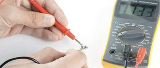
To do this, you will need a multimeter, that is, a digital measuring device. First, you should get a cheaper model, always with manual selection of the measurement range.
What does electrician study?
Science began to develop rapidly in the 19th century. At that time, the first laws were discovered that made it possible to understand what electricity is. The theoretical foundations were tested in practice. The first electrical devices began to appear, and the means of transmitting electricity from sources to consumers improved.
Electrical science was based on discoveries in the fields of mathematics, physics, and chemistry. She studied the nature, properties of current, electromagnetic fields.
Modern science helps to learn everything about devices that use electricity. Thanks to research, more advanced devices are being created. Electrical engineering is a science that has become the main engine of progress.
Voltage measurement
- connect the black wire to the “COM” connector;
- connect the red wire to the voltage measurement connector “V” (Connecting wires in another way may damage the meter);
- set the knob to the desired division - since we expect to get a value of approximately 1.5 V, then set the knob to a value of 20 in the DCV or V range (the straight line at the letter V means constant voltage);
- The metal tips of the multimeter wires touch the battery poles, but which end goes to which? Try both combinations - the result should be the same, only once it is shown as a "positive" number, in other cases it is preceded by a minus number. This doesn’t matter to us; nothing will happen to the voltmeter either;
- we read the value - in this case, the voltage of the new battery is 1.62 V;
- turn off the multimeter (don’t forget, otherwise the battery will run out).
Measuring the voltage of a 1.5 V battery: a) the red tip of the meter touches the plus of the battery - a positive result; b) the red tip of the meter touches the minus of the battery - a negative result with a minus in front of the numbers.
Attention! When carrying out measurements, in order not to damage the device, we always set the measurement range to a value exceeding the maximum result that we expect to obtain! If we don’t know what to expect, then the safest option is to set the meter to the highest possible range and then reduce it to the most accurate measurement.
Let's check other batteries/accumulators. For the tests we chose: a charged 1.2 V AA size battery - 1.34 V, a partially discharged NiMH battery - 1.25 V.
Now let’s place our 4 batteries in a common housing, the so-called holder. Then insert the ends of the battery assembly wires into the holes of the breadboard as shown in the photo below:
Battery compartment: a) empty, b) with batteries inserted, c) connected to the board
The next step is to prepare jumpers, that is, short wires that will connect the individual components on the breadboard. All you need is a piece of computer cable, wire cutters or a sharp knife.
Computer cable: a) insulated, b) after stripping
First, strip the insulation from the wire. Inside you will find thinner wires twisted together. The next step is to cut a piece of wire to the required length, remove a small, approximately 1 cm piece of insulation from both ends, and you are done. Please note that the wires in the computer cable are thin and break easily and should be handled with care and not bent frequently.
a) pliers, b) wire with stripped insulation, c) ready-made jumpers
If so, you can buy a ready-made set of jumpers. Their big advantage is that you don't have to do it yourself, and they are made from thicker wire that doesn't break as easily.
Broken end of the wire
Regardless of which jumpers you choose: handmade or ready-made, we will prepare the contact layer for further work. You will need 4 short jumpers (to connect buses that distribute voltage across the board) and two longer ones, preferably red and blue for power.
Breadboard with jumpers connecting voltage distribution buses
Now let's assemble our first circuit on a breadboard. Take a 22k ohm resistor (red/red/orange/gold stripes). What is its actual resistance? Let's check with a multimeter.
Conventional graphic symbol
The basis of any electronic device is radio components. These include resistors, LEDs, transistors, capacitors, various microcircuits, etc. To learn how to read electrical circuits, you need to know well the graphic symbols of all radio components.
For example, consider the following drawing. It consists of a battery of galvanic cells GB1, resistor R1 and LED VD1. The conventional graphic designation (UGO) of the resistor looks like a rectangle with two terminals. In the drawings it is designated by the letter R, followed by its serial number, for example R1, R2, R5, etc.
Since an important parameter of a resistor, in addition to resistance, is power dissipation, its value is also indicated in the designation.
The LED UGO has the shape of a triangle with a line at its apex; and two arrows, the tips of which are directed from the triangle. One terminal of the LED is called the anode, and the second is called the cathode.
An LED, like a “regular” diode, passes current in only one direction - from the anode to the cathode. This semiconductor device is designated VD, and its type is indicated in the specification or in the description of the circuit. The characteristics of a particular type of LED are given in reference books or “datasheets”.
Power supplies
To indicate a simple power source, a symbol consisting of 2 lines separated by a space is used. Thin long characterizes the positive pole, and short thick characterizes the negative pole. In addition, the pole designation is placed next to the lines. If you need to depict a battery consisting of several galvanic cells, then 2 symbols for the power source are connected by a short dotted line.
Wires and their connections
Conductors are indicated by thin horizontal or vertical lines. Deviation at a straight or obtuse angle is allowed. If the wires intersect, the connection point is marked with a dot.
For easier reading, such symbols may be colored. Cables are symbolized by thicker lines.
Common wire
To simplify the drawing and reading of the PS, the common wire designation is used. It represents an inverted letter "T". Its vertical crossbar is connected to all the wires, which are connected to a point with negative potential.
Radio components
Each radio component has its own designation, approved by GOST or other standards. Thanks to this, uniformity of design is achieved.
Chip
A chip (U) is a circuit that is manufactured on a wafer or film. Typically, the material for a microcircuit is silicon. The chip is not a collapsible element. At the same time, some technicians manage to identify a radio component that is in a short circuit, for example, in a non-separable Wi-Fi chip.
Resistors
Resistor (R – designation in the diagram) – for linear conversion of current to voltage and vice versa. And also to limit the current in an electrical circuit. Instead of a resistor with zero resistance, it is allowed to install a jumper, only for the duration of diagnostics. After carrying out troubleshooting activities on the phone board, install R in its place in the circuit. If the resistor is damaged, take it from the “donor” board.
We recommend reading: All about bipolar transistors: principles of operation and mode of operation, switching circuits and methods of testing for functionality
Capacitors
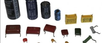
Capacitor (C) is a radio component designed to accumulate charge. In circuit design, another important property of a capacitor is used - it quickly releases a charge (discharges) when the consumer of electrical energy is turned on. In order to check the capacitor for a short circuit, you need to remove it from the circuit and take measurements with a multimeter in continuity mode. The capacitance of a capacitor depends on several factors. One of them is the geometric dimensions of the capacitor plates. In iPhone 6, if the backlight unit malfunctions, a short circuit on capacitors C1530, C1531, C1505 occurs when the board is connected to the LBP.
Coil
Coil (Fl) - filter or fuse - is designed to protect the circuit from the effects of high currents. It is a self-destructive element and is used to disconnect the closed circuit by opening it. The filter is checked with a multimeter in the circuit test mode for integrity.
Diodes
Diode (D) – conducts electric current in one direction. That is, if during measurements, the diode passes current in the opposite direction, then it is faulty. Used in the phone backlight unit. Structurally, it has 3 outputs. Anode and two cathodes. The diode is checked for serviceability with a multimeter in diode testing mode.
The polarity of the diode can be determined:
- key (tag) on the cathode,
- multimeter in diode testing mode,
- visually, on an unsoldered “donor” board.
Resistance measurement
- connect the black wire to the “COM” connector;
- connect the red wire to the red connector;
- set the switch knob - we expect to get a value of approximately 22 kOhm, so set it to 200 kOhm;
- the metal ends of the multimeter wires touch the resistor terminals (it doesn’t matter which end is which terminal);
- We calculate the value - for this resistor the resistance is 22.1 kOhm;
- turn off the device (don’t forget).
Measure the resistance of the resistor with an ohmmeter
As with batteries, the value measured by the multimeter differs from the rating of the cell being tested. The gold band on the resistor indicates a 5% tolerance.
22 kOhm x 5% = 1.1 kOhm
Therefore, the resistance range for this resistor can be from 20.9 kΩ to 23.1 kΩ. Now let’s connect the plate, the batteries in the holder and the resistor, as in the photo below:
The simplest electronic circuit is connected to a breadboard
In electronics, diagrams are used to illustrate connections between individual elements. In our case it will look like this:
The simplest electrical circuit
The symbol labeled B1 is the batteries providing a total voltage of 4 x 1.5V = 6V. And the 22k ohm resistor is labeled R1. According to Ohm's law:
I = U / RI = 6 V / 22 kOhm I = 6 V / 22000 Ohm I = 0.000273A I = 273 µA
Theoretically, the current in the circuit should be 273 μA. But that the resistance of the resistor can vary within 5%. The voltage provided by the batteries is also not the nominal 6V, and will depend on the battery charge level. Let's look at the actual voltage provided by 4 x 1.5V batteries.
Where to start learning
Electrical manuals “for dummies” are available on information portals. There is no shortage of such materials, so anyone can start studying the discipline from scratch. However, if a person plans to become an electrician, he will have to enroll in the appropriate faculty of a higher or secondary specialized educational institution.
University, technical school, college
Many educational institutions offer professional education as an electrician. It is worth considering the features of training in each of them:
- A full course at a university lasts 4-5 years. A minimum practical basis is given here. However, universities prepare specialists with good theoretical knowledge. Educational institutions accept graduates of 11th grade or secondary educational institutions.
- Technical schools provide an equal amount of theoretical and practical skills. The training is aimed at obtaining a working specialty. Therefore, the theory is studied in less detail than at a university. Technical schools accept graduates of the 9th or 11th grades of school. Training lasts 4 or 3 years, respectively.
- School or college. Such institutions prepare workers, so the theoretical part is kept to a minimum. You can get a profession as an electrician at a school in 1-3 years.
Courses
Such programs help you master basic skills in 2-8 weeks. Lessons are held both in standard and online mode. The disadvantage of the courses is the small amount of knowledge gained. A novice electrician learns the basics of electrical engineering and masters some skills. The student conducts practical classes independently.
All courses are offered on a paid basis, and you can take them without leaving another job.
Self-study
If the described teaching methods are not suitable, a person can master electrical engineering independently with the help of special literature. In this case, the electrician will not be able to perform complex tasks, but he will be able to install the wiring in the apartment. To become an experienced specialist with the help of tutorials, you need to undergo practical training as an electrician's assistant. The student must carefully monitor the actions of the mentor and complete simple tasks.
Voltage measurement
- connect the black wire to the “COM” connector;
- connect the red wire to connector “V”;
- set the switch knob - we expect to get a value of about 6 V, so we set the knob to a value of 20 in the DCV or V- range, if necessary, turn on the device, which should show 0;
- use the metal probes of the multimeter wires to touch the wires of the battery holder (depending on which end of which wire we touch, the result will be positive or negative);
- We calculate the value - the voltage of the battery assembly is 6.50 V;
- turn off the power.
Battery Assembly Voltage Measurement
Let's substitute the measured values into the formula obtained from Ohm's law:
I = U / RI = 6.5V / 22.1k Ohm I = 6.5 V / 22100 Ohm I = 0.000294A I = 294 µA
Let's try to check whether we get this result by measuring the current with a multimeter.
Electrical wire selection
Cables can be single or multi-core. In the first case, there is a single current-carrying wire. In a multicore cable, the bus consists of braided conductors. Wires are also distinguished by the number of conductive elements. To create 3-phase wiring, a 4-core cable is used. Products consisting of 3 conductors are used to create household electrical networks. The wires are made of silver, aluminum or copper.
The first option is used in industrial conditions, due to its high electrical conductivity. In everyday life, copper or aluminum is used.
Recommendations for beginners
A novice electrician should follow these tips:
- When choosing a cable cross-section, a simple law is taken into account: power is equal to voltage multiplied by current. Using this formula, the main current parameters are calculated. Using tables, the cross-section of conductors and the characteristics of other elements of the electrical network are selected.
- The wires are laid strictly horizontally or at right angles. The distance from the ceiling to the cable must be at least 20 cm. If there are pipes in the room, at least 40 cm away from them.
- Distribution boards are installed at a height of 1.2 m. A distance is left between the individual modules to ensure air circulation.
- Electrical circuits are protected by automatic switches that are triggered when current leaks.
To become an experienced electrician, you need to constantly perform practical tasks and improve your skills.
Electrical engineering and electrical mechanics
These sciences are interrelated. Electrical mechanics studies the basic circuitry of equipment that consumes electricity. The theory and practice course helps you learn how to repair household appliances. The basic principles of electrical mechanics allow you to understand how the engine and generator work, what are the differences between a stabilizer and a transformer.
Microcircuitry
Radio engineering for beginners
It is a branch of microelectronics that deals with the research and development of electrical structural designs of circuits in integrated circuits. They are microelectronic products that perform the functions of conversion, signal processing and information storage.
Important! Microcircuits have a high density of connected elements over an area of several mm2. Their elements cannot be separated from the crystal and substrate.
Microcircuitry
Circuit engineers are engaged in the design and installation of integrated circuits (ICs). There are several types of MI:
- film - all elements and inter-element components are made in the form of films;
- hybrid – contain crystals;
- analog – designed for processing signals that vary according to the law of a continuous function;
- digital – signal processing according to the discrete function law.
Safety precautions
When working with electrical networks or devices, observe the following rules:
- Before operating or repairing equipment, read the instructions. The safety section specifies unacceptable actions that can lead to short circuits and electric shock.
- The devices must be de-energized. After this, the condition of the wire insulation is assessed. If damage is detected, bare areas are covered with electrical tape.
- If it is impossible to de-energize the electrical network, work in dielectric gloves, shoes with rubber soles and special glasses.
- Access to switchboards and electrical installations is prohibited for novice specialists.
- Do not touch stripped wires with your hands. To find the phase, multimeters, indicator screwdrivers and other tools are used.
