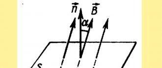
Types of electric current, flow conditions
Particles carrying a charge can move randomly through the conductor or move purposefully in a certain direction. In the second case, they talk about the presence of electric current. Its main characteristic is the presence of a displacement vector. The vector of current motion is identical to the direction of charged particles.
Chaotic and directed movement of charged particles
Important! The current flow can be constant or variable. In the first case, the flow of particles moves clearly in one direction in a straight line, without oscillations or disturbances. In the second, sinusoidal oscillations take place with a certain frequency. To transform (rectify) alternating electric current, special devices are used. In general, for the existence of a constant current, it is required that at one end of the conductor element there is always an excess of negatively charged particles, and at the other - a deficiency. A force is also required that will move these charges.
Alternating current, unlike direct current, does not require polarity. Unlike constant, it has a frequency - this is the number of changes in the direction of movement of particles per unit of time. In a standard household network, the number of such shifts is 50 per second. Various devices powered by rechargeable cells and batteries, as well as household appliances, laptops, and desktop computers consume constant electric current. The battery itself is a constant current generator, but it can be inverted into alternating current using special devices.
The current caused by the electric field is usually called conduction current. The elementary particles that carry charge differ among different types of conductor materials. In the case of metallic elements, these are free electrons; in some semiconductor materials, these are purposefully moving ions. In electrolytes (including those used in batteries), ions with positive and negative charges move in different directions. The latter is typical for all conductors that are liquids.
In a convection electric current, electrons move under the influence of inertia. Another type of current flows in vacuum conditions (this phenomenon is used in electronic light bulbs). The main characteristics of electric current are strength and current density.
Directed movement of electrons in a conductor
DC laws
Table of contents:
Electric current is the ordered movement of electric charges.
In metals, charge carriers are free electrons, in electrolytes - positive and negative ions, in semiconductors - electrons and holes, in gases - ions of both signs and electrons.
The direction of current in a conductor is taken to be the direction of positive charges. In the outer part of the circuit, which includes all its sections except the current source, the current flows from plus to minus, in the inner part, i.e. inside the current source, from minus to plus.
The section of the circuit inside the current source is called the internal part of the circuit, and the rest of the circuit, which includes current consumers, measuring instruments, control devices and connecting wires, is called the external part of the circuit.
The current strength I is the ratio of the charge q passing through the cross section of the conductor to the time of passage of this charge f:
Current strength is a scalar quantity. The SI unit of current is ampere (A). This is the SI base unit.
The current strength in a metal conductor is equal to the product of the concentration of free electrons n, the modulus of the elementary charge e, the speed of ordered movement of free electrons along the conductor v and the cross-sectional area of the conductor S:
The current strength in the circuit is measured using instruments - ammeters. The ammeter is connected to the circuit in series with the section in which the current is measured.
Current density j is the ratio of the current strength to the cross-sectional area of the conductor through which the current flows:
The current density is equal to the product of the concentration of free electrons, the modulus of the elementary charge and the speed of ordered movement of free electrons along the conductor:
Current density is a vector quantity. The current density vector is directed towards the ordered movement of positive charges along the conductor.
A conductor resists electric current. The resistance of the conductor R is equal to the ratio of the voltage U on the conductor to the current I in it:
Resistance is a scalar and always positive quantity. The SI unit of resistance is ohm.
The resistance of linear conductors is directly proportional to their length I and inversely proportional to their cross-sectional area S:
Here is the specific resistance of the conductor substance.
Resistivity is a positive scalar quantity. It depends on the substance and temperature of the conductor.
As the temperature of the conductor increases, the thermal vibrations of the lattice ions intensify, so the resistance of the conductor to the passage of current increases. The dependence of the resistance of metals on temperature is expressed by the formulas
Ohm's law
The basic law of electrodynamics is Ohm's law. Ohm's law for a conductor (section of a circuit): the current strength in a conductor is directly proportional to the voltage at its ends and inversely proportional to the resistance of the conductor:
Conductors for which Ohm's law holds are called resistors. All metal conductors are resistors. The current-voltage characteristic of the resistor, i.e. The graph of the dependence of the current in the resistor on the voltage applied to it is a straight line (Fig. 198). The cotangent of its inclination angle a to the voltage axis is numerically equal to the resistance of the resistor:
Conductors can be connected in series and in parallel (Fig. 199).
When connecting conductors in series (Fig. 199, a): R,
1) the current strength in all conductors is the same;
2) the total voltage is equal to the sum of the voltages on the individual conductors:
3) the total resistance is equal to the sum of the resistances of the individual conductors:
If all conductors have the same resistance, then
The voltages on two series conductors are directly proportional to their resistances:
- for two serial conductors.
When connecting conductors in parallel (Fig. 199, b):
1) the voltages on all conductors are the same;
2) the current strength in the general (unbranched) section of the circuit is equal to the sum of the current strengths in the individual conductors:
3) the reciprocal of the total resistance is equal to the sum of the reciprocals of the resistances of individual conductors:
If all N conductors connected in parallel have the same resistance, then the current strength in the common part of the circuit and their total resistance are determined by the formulas:
The total resistance of two parallel conductors can be calculated using the formula
and three - according to the formula
The current strengths in two parallel conductors are inversely proportional to their resistances:
The voltage on parallel branches can be found by multiplying:
a) the strength of the total current on the total resistance of the entire parallel section;
b) multiplying the current in any parallel branch by its resistance;
If you come across a diagram similar to the one in Fig. 200, but, pay attention to whether there is symmetry between the resistances to the left and right of the jumper ab, as well as between the upper and lower resistances. If there is, then points a and b have the same potential and, therefore, the potential difference between them is zero. Therefore, no current will flow through the jumper with resistance R and it can be excluded from the circuit (Fig. 200, b), significantly simplifying the calculation of the total resistance:
Remember: all ends of conductors with the same potentials can be connected into one node or, conversely, separated, resulting in a simpler circuit, the total resistance of which will remain the same.
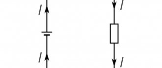
If a capacitor is connected to a certain section of the circuit, then direct current will not flow through this section, but a potential difference will arise on the plates of the capacitor equal to the potential difference at the ends of this section.
If the conductor is an alloy of different metals evenly distributed throughout its volume, then it can be represented as a parallel connection of conductors from each metal separately. In this case, the length of each of these conductors is equal to the length of the alloy conductor, and the cross-sectional area of the alloy conductor is equal to the sum of the cross-sectional areas of the conductors from the individual metals included in the alloy. For example, if a copper-steel alloy conductor has a length l and a cross-sectional area S, then its resistance R can be determined in terms of the resistance of the copper and steel sections as follows:
and besides, .
Ammeter is a device for measuring current. Since the current strength is the same when the conductors are connected in series, the ammeter is connected in series with the section of the circuit in which the current strength is measured.
Each ammeter is designed for a certain maximum current strength, which cannot be exceeded, otherwise the device will “burn out” and become damaged. The maximum possible current for a given ammeter is usually indicated on the device body and in its passport. But sometimes it is necessary to measure a greater current strength than that for which a given ammeter is designed, and there is no other device at hand. To do this, it is enough to connect a certain resistance to it in parallel, which is called a shunt, and this operation itself is called shunting the device.
Let the ammeter have a resistance and be designed to measure currents no more than , but you want to measure a current with an intensity that is N times greater than the current,
If current is applied directly to the ammeter, the device will be damaged. To prevent this from happening, part of the current is diverted to a shunt Ш parallel to the ammeter (Fig. 201),
the resistance of which is selected such that the ammeter can measure currents up to .
The shunt resistance is calculated using the formula
A voltmeter is a device designed to measure voltage in a circuit. Since the voltage is the same when the conductors are connected in parallel, the voltmeter is connected in parallel to the section where the voltage is measured.
The maximum voltage for which this voltmeter is designed is indicated in its passport and on the case
device. But sometimes you need to measure a voltage greater than the maximum voltage for which the voltmeter is designed. To prevent the device from “burning out”, a resistance (resistor) is connected to it in series, which is called “additional resistance” (Fig. 202).
Let the maximum permissible voltage on the voltmeter be , and we need to measure the voltage on the section of the circuit ab to which the voltmeter is connected and which is N times greater:
those. we want to increase the scale division price of the device N times.
In order for a voltmeter to measure a voltage N times greater than the voltage for which it is designed, the additional resistance connected to it in series must be N - 1 times greater than the resistance of the voltmeter itself:
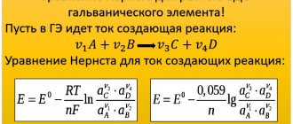
In a current source, in addition to Coulomb forces, free charges are also affected by forces of non-electrostatic origin (chemical in galvanic cells and batteries, mechanical and magnetic in current generators, etc.). These forces are called third-party forces.
Extraneous forces are forces of non-electrostatic origin that can maintain a potential difference at the ends of a conductor.
In a current source, external forces FCT perform the work of charge separation at the poles of the source. It is these forces that force positive charges to move towards the positive pole of the source, which repels them. To characterize the ability of external forces to perform more or less work of moving charges, the concept of electromotive force (EMF) was introduced.
Electromotive force is equal to the ratio of the work done by external forces to the amount of charge q they move:
EMF is a scalar algebraic quantity, i.e. it can be positive or negative. The emf of a source is considered positive if, bypassing a circuit containing several current sources in an arbitrarily chosen direction, we move inside the source (in a narrow interval between a thick and short line indicating the negative pole of the source and a long thin line indicating its positive pole) in the upward direction potential, i.e. from thick short (minus) to long thin (plus).
In Fig. 203 shows a circuit in which three current sources with EMF are included. The arrow inside the contour shows the direction of any traversal of the contour, i.e. we go around the circuit clockwise. At the same time, in a current source with EMF we move towards increasing the potential, i.e. from minus to plus, so the emf of this current source is positive. In a current source with EMF, on the contrary, we move towards a decrease in potential, moving from plus to minus, therefore the EMF of this source is negative. For the same reasons, EMF is also negative.
The resulting EMF of the circuit is equal to the algebraic sum of the EMF of each source. Therefore, the EMF of the circuit shown in Fig. 203, equal to:
The SI unit of emf is the same as the unit of potential and voltage, i.e. volt (V).
The emf of the source is equal to the potential difference at its poles when the external circuit is open. Therefore, to measure the emf of a source, you need to open the circuit in which it is connected and connect a voltmeter to its poles.
If there is no EMF acting on this section of the circuit, i.e. if there is no current source, then
The voltage on the section of the circuit that does not contain EMF is equal to the potential difference at the ends of this section.
The emf of the current source is equal to the sum of the voltages in all sections of the closed circuit.
A voltmeter connected to the poles of the current source in a closed circuit shows the total voltage across the entire outer part of the circuit.
- Ohm's law for a complete (closed) circuit.
Ohm's law for a complete (or closed) circuit: the current strength in the circuit is directly proportional to the emf of the current source and inversely proportional to the sum of the resistances of the external and internal sections of the circuit.
If the circuit contains N identical current sources connected in series, i.e. opposite poles (Fig. 204, a), then both the EMF and the internal resistance of such a battery increase N times compared to the EMF and internal resistance of one current source. Then the formula of Ohm’s law for a closed circuit with N identical sources connected in series will take the form:
Current sources with the same EMF and internal resistance are considered identical.
If the circuit contains N identical current sources connected in parallel, i.e. poles of the same name (Fig. 204, b), then the emf of such a battery is equal to the emf of one element, and the internal resistance decreases N times compared to the internal resistance of one element. Then Ohm's law for a circuit containing N identical current sources connected in parallel will take the form:
If the poles of the current source are closed by a conductor with negligible resistance, i.e. if the circuit does not contain external resistance (load) R, then such a connection of the ends of the circuit is called a short circuit. During a short circuit, Ohm's law for the complete circuit will take the form:
at — short circuit current strength.
In a circuit with serial and parallel conductors (Fig. 205), we advise you to derive the total current from the plus of the current source - it can be designated - and conduct it, without changing the index, to the first node. A node is a place where more than two conductors are connected. Next, this current branches out along parallel conductors and its index changes.
We now advise you to set the index of the current strength in the parallel branch to the same as the index of the resistance through which this current flows.
At the last node, currents flowing along parallel branches flow into a common current that also flows through the current source. The current strengths in parallel conductors are the same only if the resistances of these conductors are the same. The sum of the currents entering the node is equal to the sum of the currents leaving the node.
In the formula of Ohm's law for a closed circuit, resistance R is always the total resistance of the entire external part of the circuit, and current strength I is the current strength only in the unbranched section of the circuit, but not in individual parallel branches.
In any electrical circuit, the energy of the current source is converted into other types of energy in consumers, and at the same time the electric current performs one or another work. Work of current in a given section of the circuit
The work done by the current in a given section of the circuit is equal to the product of the voltage in this section, the current strength in it and the time the current passes.
The SI unit of work is the joule (J): 1 J = 1 V • A • s.
The formula for the work of current can also be written as follows:
The speed at which the current performs work in a given section of the circuit is characterized by the current power P. The current power is equal to the ratio of the work to the time during which it is completed:
Taking into account the above formulas, the current power formula can be expressed as follows:
When current passes through a conductor, positive ions in the nodes of the crystal lattices of the conductor begin to vibrate more strongly due to the energy of the current, which is accompanied by an increase in the internal energy of the conductor, i.e. by heating it. In this case, the current energy is released in the form of heat, which is called Joule heat.
Joule-Lenz law
Joule-Lenz law: the amount of heat released in a conductor when an electric current passes through it is directly proportional to the square of the current strength, the resistance of the conductor and the time of passage of the current:
The Joule-Lenz law can be written differently, using Ohm’s law for a section of the circuit:
The efficiency of an electrical circuit d) can be determined by the ratio of the voltage U in the area where useful work is performed or thermal energy is usefully used, to the emf 8 of the current source:
or
Here R is the resistance of the entire external part of the circuit, and r is the resistance of the current source (internal resistance).
Electrolytes are substances that break down into ions in a liquid state. These include acids, salts and bases, as well as their melts. Current in an electrolyte is the ordered movement of ions of opposite sign under the influence of an electric field in the electrolyte.
The phenomenon of the release of a substance on the electrodes when an electric current passes through the electrolyte is called electrolysis.
Faraday's law
The English scientist M. Faraday , while studying experimentally the phenomenon of electrolysis of various substances, discovered a law called Faraday’s first law for electrolysis: the mass of a substance m released on the electrode during electrolysis is directly proportional to the charge q passing through the electrolyte:
The proportionality coefficient k in this formula is called the electrochemical equivalent of the substance released at the electrode.
The electrochemical equivalent is a positive scalar quantity. Its SI unit is kg/C.
The value of the electrochemical equivalent of various substances is given in reference books and problem books on physics.
Since from the definition of current strength it follows that
then, substituting this expression instead of q in the previous formula, we obtain another entry for Faraday’s first law for electrolysis:
Here I is the current strength in the electrolyte, t is the time it passes, i.e. electrolysis time.
Another formulation of Faraday's first law for electrolysis: the mass of the substance released on the electrode during electrolysis is directly proportional to the strength of the current in the electrolyte and the time it passes.
During electrolysis, the release of a substance occurs simultaneously on both electrodes. Since in this case different substances are released at the cathode and anode, their masses are different, since their electrochemical equivalents are different.
Another entry for Faraday's law for electrolysis:
This expression is sometimes called Faraday's combined law for electrolysis. Its formulation: the mass of a substance m released on the electrode during electrolysis is directly proportional to the molar mass M of this substance, the current strength in the electrolyte I, the electrolysis time t and inversely proportional to the valence n of this substance. Here C/mol is the Faraday number.
If in the electrolysis problem something is said about the thickness h of the substance released on the electrode, then its mass m can be expressed through the density p and volume V, and the volume through the thickness and coating area S:
Metals are classified as conductors of the first kind. When current passes through them, no substance transfer occurs. The same conductors include semiconductors. Conductors of the second type, in which matter is transferred during the passage of current, include electrolytes and gases.
Semiconductors are substances whose resistivity is greater than that of metals, but less than that of dielectrics. At low temperatures, a chemically pure semiconductor is a dielectric - it does not conduct electric current. At high temperatures, due to the energy of the heater, free charge carriers appear in the semiconductor - electrons and holes, which can move through the semiconductor under the influence of an electric field. In this case, the holes behave like positive charges. The conductivity of chemically pure semiconductors is called electron-hole conductivity.
As temperature increases, the resistance of a semiconductor decreases due to an increase in the number of electrons and holes. This is the main difference between semiconductors and metals, whose resistance increases when heated.
Impurity conductivity is the conductivity of a semiconductor with an impurity having a different valence than the main semiconductor. If the valence of the impurity is greater than the valence of the main semiconductor, then the impurity is called a donor, and the conductivity is called donor or n-type conductivity. In donor conduction, charge carriers are free electrons.
If the valence of the impurity is less than the valence of the main semiconductor, then the impurity is called an acceptor, and the conductivity is called acceptor or p-type conductivity. In acceptor conduction, the charge carriers are holes.
The junction of two semiconductors with different types of conductivity is called a pn junction. The main property of a pn junction is its increased resistance compared to other parts of semiconductors.
If the majority charge carriers flow through the pn junction, then the current is called direct, and if minority charge carriers flow through the pn junction, then the current is called reverse and it is significantly less than the forward current. The property of a pn junction semiconductor to pass a large forward current and significantly reduce the reverse current is used to rectify alternating current.
In Fig. 206 a) shows a circuit for half-wave rectification of alternating current with a semiconductor diode D, and in Fig. 206, b) - a full-wave rectification circuit using four semiconductor diodes. Solid arrows show the direction of current flowing during one half-cycle of alternating current, and dashed arrows show the direction of current flowing during the second half-cycle.
Gas does not conduct electric current under normal conditions. In order for a gas to become a conductor of current, it must be ionized—the neutral molecules and atoms of the gas must be broken down into charged particles. Ionizers can be a gas burner flame, fast electron beams, or gamma rays. If electrodes are placed in ionized gas and connected to the poles of a current source, then an electric current will flow through the gas. This phenomenon is called gas discharge.
Current in a gas is the ordered movement of electrons and ions of both signs under the influence of an electric field between electrodes introduced into the ionized gas.
In technology, high vacuum is understood as a state of gas in a vessel when the remaining atom or molecule in it can fly from the wall of the vessel to the opposite wall without experiencing a single collision with oncoming atoms or molecules. Such a vacuum is created in vacuum devices, for example, in vacuum diodes, triodes, cathode ray tubes, etc.
The source of charges in such devices is a heated electrode that emits thermionic electrons. The emission of free electrons by a hot metal is called thermionic emission.
If at the same time a minus is applied to the heated electrode, i.e. make it a cathode, and apply a plus to the opposite electrode, i.e. make it an anode, then a current will flow in the vacuum.
Current in a vacuum is the ordered movement of charged particles under the influence of an electric field between the cathode and anode. As a rule, such particles are electrons. A vacuum tube with a heated cathode and an opposite anode is called a two-electrode vacuum tube or vacuum diode. Its schematic representation is shown in Fig. 207.
A vacuum diode is used to rectify alternating current.
This theory is from the page for detailed solutions to problems in physics, there is a theory and detailed solutions to problems on all topics in physics:
Physics problems with solutions
You might find these pages useful:
| Electromagnetism in physics: basic formulas |
| Electrostatics basic concepts, laws and formulas |
| Magnetism in physics: basic formulas, laws and rules |
| Mechanical vibrations in physics: basic formulas and laws |
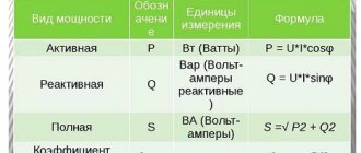
Current Density and Power
Current work - how is it measured?
The work that the electric field does on sources of current motion can be characterized by power density (it is equal to the energy divided by the product of the volume of the conductor and the time period). The most common way for this power to be dissipated into external space as thermal energy. But some of it can be converted into mechanical energy (for example, during the operation of an electric motor) or into various types of radiation.
What is current strength?
So, now let’s apply everything we wrote here about water to electronics. The wire is a hose. A thin wire is a thin-diameter hose, a thick wire is a thick-diameter hose, one might say a pipe. Water molecules are electrons. Therefore, a thick wire can carry more electrons at the same voltage than a thin wire. And here we come close to the very terminology of current strength.
Current is the number of electrons passing through the cross-sectional area of a conductor in any given time.
It all looks something like this. Here I drew a round wire, “cut” it and got the same cross-sectional area. It is through this that electrons flow.
For a period of time take 1 second.
Ohm's law
Magnetic field energy density
For a conductive medium with isotropic characteristics, this law has the following form:
j=E* σ,
where j is the density of the flowing electric current, E is the field strength at the point under consideration (a scalar quantity, like the previous one), and σ is the specific conductivity of the environment.
As for the work of the electric field for such a medium ( w ), it can be expressed by the following formulas:
w= E2* σ=j2/σ=p*j2 (p here is resistivity).
The expression for work in this case will take the form:
w=E* σ *E=j*p*j (E and j in this case are scalar quantities).
In a right-to-left matrix, a column vector is multiplied by a row vector and by a matrix. Tensor quantities p and σ generate their corresponding quadratic forms.
Volumetric magnetic energy density
The formula for finding the volumetric energy density is as follows:
ω=W/V.
By ω here we mean the actual density being sought, by W the energy of the existing field, and V the volume of space in which the field is active. If we express the value of W in terms of magnetic permeability µ and induction B and substitute it into the formula, it will take the following form:
ω=B2/2* µ0* µ (here µ0 is the magnetic constant).
Conversion using the induction vector is used to eliminate the binding of the active magnetic field to the characteristics of the inductor. The formula for calculating the induction characteristic looks like this:
B= µ0* µ*I*n.
I here is the current force in the coil circuit; n is used to express a value such as the density of the winding. It is equal to the quotient of the number of turns in the solenoid winding and the length of the fragment on which the turns are located. Then the formula for W
W= B2*V/2* µ0* µ.
By substituting the expression into the basic density formula, you can bring it to the previously designated form.
Unit of measurement of electric current density
Allowable current for copper wires - current density in a copper conductor
To express the density value, the derivative is used from the units of current strength (Ampere) and cross-sectional area (square meter), as well as submultiples and multiples of the indicated ones. Density is usually measured in amperes divided by square meter (A/m2). Instead of the word “density”, “electric current saturation” is sometimes used.
Important! Because a quantity has a direction, it is categorized as a vector (or scalar). This vector runs along the axis of the electric current.
Simple explanation
Current density J is a vector physical quantity characterizing the electric charge flux density at the point under consideration.
Wikipedia
High electrical current density causes the cable to heat up. Therefore, care must be taken not to exceed the permissible current carrying capacity of the line or conductor. In addition, the effective cross-section of the conductor may decrease when exposed to high-frequency signals (skin effect), which increases the current density. Therefore, when choosing a conductor, it is necessary to take into account not only the actual current, but also the frequency of the signal.
Calculation formula
The value under consideration is inversely dependent on the cross-sectional dimensions (the larger the area, the lower the current density) and the time period of passage of the electric charge, and directly dependent on the magnitude of this charge.
This can be written like this:
j=Δq/ΔtΔS (q here is an elementary small charge, t is an infinitely small period of time, and S is the cross-sectional area).
Since the current force is expressed as the quotient of the charge and the time interval of its passage, the formula can be written as follows:
j=I/ΔS.
The formula for current density based on the parameters of moving charges will look like this:
j=q*n*V (V here is the speed, and n is the concentration of electron particles).
Current strength from a hydraulic point of view
I think you have heard the phrase “ current strength ” more than once.
What is strength needed for? Well, why? To do useful or useless work. The main thing is to do something. Each of us has some kind of power. Someone has such strength that he can smash a brick to smithereens with one blow, while another cannot even lift a straw. So, my dear readers, electric current also has power. Imagine a hose with which you water your garden.
Let's now make an analogy. Let the hose be a wire, and the water in it be an electric current. We opened the faucet slightly and water immediately ran through the hose. Slowly, but still she ran. The jet force is very weak.
Now let's open the faucet to its fullest. As a result, the stream will gush with such force that you can even water your neighbor’s garden.
In both cases the hose diameter is the same.
Now imagine that you are filling a bucket. Which hose will fill it with water pressure faster? Of course from the green, where the water pressure is very strong. But why does this happen? The thing is that the volume of water coming out of the yellow and green hoses in an equal period of time is also different. Or in other words, a much larger number of water molecules will run out of the green hose than from the yellow hose over an equal period of time.
Let's look at another interesting example. Let's say that we have a large pipe, and two others are welded to it, but one is half the diameter of the other.
From which pipe will the volume of water come out more per second? Of course, with the one that is thicker in diameter, because the cross-sectional area S2 of the large pipe is larger than the cross-sectional area S1 of the small pipe. Therefore, the force of flow through the large pipe will be greater than through the small pipe, since the volume of water that flows through the cross section of pipe S2 will be twice as large as through the thin pipe.
4-vector current density
This designation from the theory of relativity is intended to generalize the phenomenon of density to the space-time continuum, operating in four dimensions. Such a four-vector includes a three-vector expression of the current density (scalar quantity) and the volumetric electric charge density. The use of a four-vector makes it possible to formulate electrodynamic equations in a covariant manner.
The quantity under consideration is necessary to describe the concentration and uniformity of distribution of charged microparticles over a conductor material in which one or another form of electric current exists. When operating with expressions containing a quantity, you must not forget about its scalarity.
Current formula
The formula for dummies will look like this:
Where
I - actual current strength, Amperes
N - number of electrons
t is the period of time during which these electrons travel through the cross section of the conductor, seconds
The more correct (official) formula looks like this:
Where
Δq is the charge over a certain period of time, Coulomb
Δt — the same period of time, seconds
I - current, Amperes
What's so funny about these two formulas? The thing is that an electron has a charge of approximately 1.6 10-19 Coulomb. Therefore, for the current strength in the wire (conductor) to be 1 Ampere, we need a charge of 1 Coulomb = 6.24151⋅1018 electrons to pass through the cross section. 1 Coulomb = 1 Ampere · 1 second.
So, now we can officially say that if 6.24151⋅1018 electrons fly through the cross-section of a conductor in 1 second, then the current strength in such a conductor will be equal to 1 Ampere! All! There is no need to invent anything else! Tell your physics teacher so.)
If the teacher doesn’t like your answer, then say something like this:
Current strength is a physical quantity equal to the ratio of the amount of charge passing through the surface (read as through the cross-sectional area) over some time. Measured as Coulomb/second. To save time and according to other moral and aesthetic standards, they agreed to call the coulomb/second Ampere, in honor of the French physicist.
Current strength in the conductor
Very often you can see physics problems with the question: what is the current strength in the conductor ? A conductor, also known as a wire, can have various parameters: diameter, also known as cross-sectional area; the material from which the wire is made; length, which also plays an important role.
And in general, the conductor resistance is calculated using the formula:
conductor resistance formula
A table with resistivities of different materials looks like this.
table with resistivity of substances
In order to find the current strength in a conductor , we must use Ohm's law for a section of the circuit. It looks like this:
Ohm's law
Task
We have a copper wire 1 meter long and its cross-sectional area is 1 mm2. How much current will flow in this conductor (wire) if a voltage of 1 Volt is applied to its ends?
problem on current strength in a conductor
Solution:
How to measure current?
In order to measure the value of current, we must use special devices - ammeters. Currently, current can be measured using a digital multimeter, which can measure current, voltage, resistance and much more. In order to measure the current, we must insert our device into the open circuit like this.
You can read more details on how to do this in this article.
I also advise you to watch a training video where a very smart teacher explains in simple language what “current strength” is.