Ideal EMF source
We have an EMF source
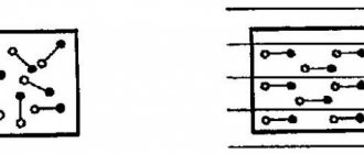
Let's remember what EMF is. EMF is something that creates an electric current. If we connect any load to such a voltage source (even a billion halogen lamps connected in parallel), it will still produce the same voltage as it would have produced if we had not connected any load at all.
Or simpler:
In short, no matter how much current passes through the resistor circuit, the voltage at the ends of the EMF source will always be the same. Such an EMF source is called an ideal EMF source .
But as you know, nothing is ideal in our world. That is, if our battery had an ideal source of EMF, then the voltage at the battery terminals would never sag. But it sags, and the more, the more current the load consumes. Something is wrong here. But why does this happen?
Definition of EMF in physics
EMF – electromotive force. Symbolized by the letter E or the small Greek letter epsilon.
Electromotive force is a scalar physical quantity that characterizes the work of external forces ( forces of non-electrical origin ) acting in electrical circuits of alternating and direct current.
EMF , like voltage , is measured in volts. However, EMF and voltage are different phenomena.
Voltage (between points A and B) is a physical quantity equal to the work of the effective electric field performed when transferring a unit test charge from one point to another.
Internal resistance of the EMF source
The thing is that a resistance is “hidden” in the battery, which, relatively speaking, clings in series with the source of the battery’s emf. It is called internal resistance or output resistance. Indicated by a small letter “ r ”.
It all looks like this in the battery:
We hook the light bulb
So, what do we get in its pure form?
A light bulb is a load that has resistance. So, we simplify the diagram even more and get:
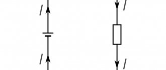
We have an ideal EMF source, internal resistance r and load resistance R. Recall the article voltage divider. It says that the voltage of the EMF source is equal to the sum of the voltage drops across each resistance.
The voltage UR drops across the resistor R, and the voltage Ur drops across the internal resistor r.
Now let's remember the article current divider. The current flowing through series-connected resistances is the same everywhere.
Let's remember algebra for 5th grade and write down everything that we just talked about. From Ohm's law for a section of the chain we obtain that
Further
Emf of a galvanic cell - formula
The electromotive force of a battery can be calculated in two ways:
- Perform calculations using the Nernst equation. It will be necessary to calculate the electrode potentials of each electrode included in the GE. Then calculate the EMF using the formula.
- Calculate the EMF using the Nernst formula for the total current-generating reaction that occurs during the operation of the GE.
Thus, armed with these formulas, it will be easier to calculate the electromotive force of the battery.
Voltage sag
So, meet the car battery!
For further use, solder two wires to it: red to positive, black to negative
Our ward is ready for battle.
Now we take a car halogen light bulb and also solder two wires with alligators to it. I soldered the low beam to the terminals.
First of all, let's measure the voltage at the battery terminals
12.09 volts. This is quite normal, since our battery produces exactly 12 volts. Let me jump ahead a little and say that now we have measured the EMF.
We connect the halogen lamp to the battery and measure the voltage again:
Have you seen it? The voltage at the battery terminals dropped to 11.79 Volts!
Let's measure how much current our lamp consumes in Amperes. To do this, we create the following diagram:
The yellow multimeter will measure voltage, and the red multimeter will measure current. You can read how to measure current and voltage using a multimeter in this article.
Let's look at the instrument readings:
As we can see, our lamp consumes 4.35 Amperes. The voltage dropped to 11.79 Volts.
Let's replace the halogen lamp with a simple 12 Volt incandescent lamp from a motorcycle
Let's look at the readings:
The light bulb consumes a current of 0.69 Amps. The voltage dropped to 12 volts exactly.
What conclusions can be drawn? The more current the load consumes, the more the battery voltage drops.
Faraday and Lenz's laws
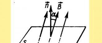
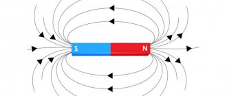
Magnetic induction lines
If electromagnetic induction is considered, the formulas of these scientists help clarify the mutual influence of significant system parameters. Faraday's definition allows us to clarify the dependence of the emf ( E - average value) on changes in magnetic flux (Δ F ) and time (Δ t ):
E = - ΔF/ Δt.
Interim conclusions:
- the current increases if per unit time the conductor crosses a larger number of magnetic force lines;
- “-” in the formula helps to take into account the mutual relationships between the polarity E, the speed of movement of the frame, and the direction of the induction vector.
Lenz substantiated the dependence of EMF on any changes in magnetic flux. When the coil circuit is closed, conditions are created for the movement of charges. In this embodiment, the design is converted into a typical solenoid. A corresponding electromagnetic field is formed next to it.
This scientist substantiated an important feature of induced emf. The field generated by the coil prevents changes in the external flow.
How to find the internal resistance of an EMF source
Let's go back to this photo again
Since in this case the circuit is open (there is no external load), therefore the current in circuit I is equal to zero. This means that the voltage drop across the internal resistor Ur will also be zero. As a result, we are left with only the EMF source, from which we measure the voltage. In our case, EMF = 12.09 Volts.
As soon as we connected the load, the voltage immediately dropped across the internal resistance and the load, in this case the light bulb:
Now at the load (on a halogen) the voltage drops UR = 11.79 Volts, therefore, at the internal resistance the voltage drop is Ur = E-UR = 12.09-11.79 = 0.3 Volts. The current strength in the circuit is equal to I = 4.35 Amperes. As I already said, our EMF is equal to E = 12.09 Volts. Therefore, from Ohm’s law for a complete circuit we calculate what our internal resistance r will be equal to
From electrostatics to electrokinetics
Between the end of the 18th and the beginning of the 19th century, the work of scientists such as Coulomb, Lagrange and Poisson laid the mathematical foundations for the determination of electrostatic quantities. Progress in the understanding of electricity at this historical stage is obvious. Franklin had already introduced the concept of “amount of electrical substance,” but so far neither he nor his successors have been able to measure it.
Following Galvani's experiments, Volta tried to find evidence that the animal's "galvanic fluids" were of the same nature as static electricity. In his search for truth, he discovered that when two electrodes of different metals come into contact through an electrolyte, both become charged and remain charged despite the circuit being closed by the load. This phenomenon did not correspond to existing ideas about electricity because electrostatic charges in such a case had to recombine.
Volta introduced a new definition of the force acting in the direction of separating charges and maintaining them in this state. He called it electromotive. Such an explanation for the description of battery operation did not fit into the theoretical foundations of physics at that time. In the Coulomb paradigm of the first third of the 19th century. d.s. Volta was determined by the ability of some bodies to generate electricity in others.
Ohm made the most important contribution to the explanation of the operation of electrical circuits. The results of a series of experiments led him to the construction of the theory of electrical conductivity. He introduced the quantity “voltage” and defined it as the potential difference across the contacts. Like Fourier, who in his theory distinguished between the amount of heat and temperature in heat transfer, Ohm created a model by analogy relating the amount of charge transferred, voltage and electrical conductivity. Ohm's law did not contradict the accumulated knowledge of electrostatic electricity.
You might be interested in the material from which the artificial ground electrode should be made
Then, thanks to Maxwell and Faraday, explanatory models of current received a new field theory. This allowed the development of a field-related energy concept for both static potentials and electromotive force. The main dates for the evolution of the concept of EMF:
- 1800 - creation of the Voltaic galvanic battery;
- 1826 - Ohm formulates his law for a complete chain;
- 1831 - discovery of electromagnetic induction by Faraday.
Conclusion
Internal resistance occurs not only in various chemical voltage sources. Various measuring instruments also have internal resistance. These are mainly voltmeters and oscilloscopes.
The point is that if we connect a load R, the resistance of which is less than or even equal to r, then the voltage will drop very significantly. This can be seen if you short-circuit the battery terminals with a thick copper wire and measure the voltage at the terminals at this time. But I do not recommend doing this under any circumstances! Therefore, the higher the resistance of the load (that is, the higher the load resistance R), the less influence this load has on the source of electrical energy.
When measuring voltage, a voltmeter and an oscilloscope also slightly drain the voltage of the voltage source being measured, because they are loads with high resistance. This is why the most accurate voltmeter and oscilloscope have a very high resistance between their probes.
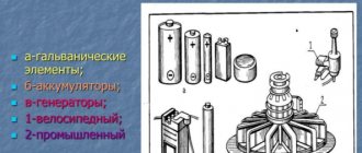
Where are different types of EMF used?
- Piezoelectric is used when stretching or compressing a material. It is used to make quartz energy generators and various sensors.
- The chemical is used in galvanic cells and batteries.
- Induction appears when a conductor crosses a magnetic field. Its properties are used in transformers, electric motors, and generators.
- Thermoelectric is formed when contacts of different types of metals are heated. It has found its application in refrigeration units and thermocouples.
- Photoelectric is used to produce photocells.
Movement of a wire in a magnetic field
As shown in the first formula (E = B * l * v * sinα), the amplitude of the electromotive force largely depends on the parameters of the conductor. More precisely, the influence is exerted by the number of power lines per unit length of the circuit’s working area. A similar conclusion can be drawn taking into account changes in movement speed. One should not forget about the relative position of the marked vector quantities (sinα).
Important! The movement of a conductor along the lines of force does not provoke the induction of an electromotive force.
Mutual induction
If you assemble a module from two coils, under certain conditions you can observe the phenomenon of mutual induction. A basic measurement will show that as the distance between elements increases, the magnetic flux decreases. The opposite phenomenon is observed as the gap decreases.
To find suitable components when creating electrical circuits, you need to study thematic calculations:
- you can take as an example coils with different numbers of turns (n1 and n2);
- mutual inductance ( M I passes through the first circuit will be calculated as follows:
M2 = (n2 * F)/ I1
- after transforming this expression, determine the value of the magnetic flux:
F = (M2/ n2) *I1
- To calculate the emf of electromagnetic induction, the formula is suitable from the description of the basic principles:
E2 = — n2 * ΔF/ Δt = M 2 * ΔI1/ Δt
If necessary, you can use a similar algorithm to find the ratio for the first coil:
E1 = - n1 * ΔF/ Δt = M 1 * ΔI2/ Δt.
It should be noted that in this case it is the force (I2) in the second operating circuit that matters.
The joint influence (mutual induction - M) is calculated using the formula:
M = K * √(L1 * l2).
A special coefficient (K) takes into account the actual coupling force between the coils.
Electromagnetism
Basic formulas of electromagnetism
Multiplicity of electric charge
Here q is the charge (C), N is the number of uncompensated elementary charges in charge q (dimensionless), and is the elementary charge (C).
Surface charge density
Here is the surface charge density, q is the charge on the surface (C), S is the area of this surface.
Coulomb's law
Here F is the force of interaction of point charges (N), is the proportionality coefficient, and is the moduli of interacting charges (C), is the relative dielectric constant of the medium (dimensionless), is the electrical constant, r is the distance between charges (m).
Electric field strength
Here E is the electric field strength (N/C or V/m), F is the force acting on the charge (N), q is the charge (C).
Point charge field strength
Here E is the field strength (N/C or V/m), k is the proportionality coefficient, q is the charge modulus (C), is the relative dielectric constant of the medium (dimensionless), is the electrical constant (F/m), r is the distance from points with tension E to charge q (m).
Field strength of an infinite uniformly charged plane
Here E is the electric field strength (V/m), is the surface density of charges on the plane, £0 is the electric constant (F/m), is the dielectric constant of the medium (dimensionless).
Field strength of two oppositely and uniformly charged planes with the same surface charge density (field strength of a flat capacitor)
All values are the same as in the previous formula.
The work of moving a charge in a uniform electric field
Here A is the work of moving a charge (J), E is the intensity of a uniform field (N/C or V/m), q is the charge being moved (C), d is the projection of displacement onto the uniform field line of force (m).
Electric field potential
Here is the electric field potential (V), is the potential energy of the charge (J), q is the charge possessing this energy in the electric field (C).
Point charge field potential
All quantities are the same as in a similar tension formula.
Potential difference
Here is the potential difference between two points of the field (V), U is the voltage (V), A is the work of moving the charge (J), q is the moved charge (C).
Relationship between tension and potential difference in a uniform electric field
Here E is the electric field strength (N/C or V/m), is the potential difference between two points of the field (V), U is the voltage between these points (V), d is the projection of the distance between these points onto the field line (m ).
Electrical capacity of the conductor
Here C is the capacitance of the conductor (F), q is the charge of the conductor (C), and is its potential (V).
Spherical conductor capacitance
Here C is the capacitance of the spherical conductor (F), is the electrical constant (F/m), is the relative dielectric constant of the medium (dimensionless), R is the radius of the sphere (m).
Capacitor capacity
Here C is the capacitance of the capacitor (F), q is its charge (C), is the potential difference between its plates (V), U is the voltage between the plates (V).
Capacitance of parallel plate capacitor
Here C is the capacitance of a flat capacitor (F), is the electrical constant (F/m), is the relative dielectric constant of the medium (dimensionless), S is the area of the capacitor plates, d is the distance between the plates (m).
Series connection of capacitors
q - the same on all capacitors
If all capacitors have the same capacitance C, then
Here q is the charge of capacitors (C), is the total voltage on the capacitor bank (V), is the voltage on individual capacitors (V), N is the number of capacitors (dimensionless), is the total capacity of the capacitor bank (F), is the capacitance of individual capacitors ( F).
Parallel connection of capacitors
U - the same on all capacitors
If all capacitors have the same capacitance C, then
Here U is the voltage on the capacitors (V), is the total charge of the bank of capacitors (C), is the charges of individual capacitors (C), N is the number of capacitors (dimensionless), is the capacity of the bank of capacitors (F), , is the capacity of individual capacitors (F ).
Formulas for the energy of the electric field of a conductor
Here is the energy of the electric field (J), C is the capacitance of the conductor (F), is the potential of the conductor (V), q is the charge of the conductor (C).
Formulas for the energy of the electric field of a capacitor
Here is the energy of the electric field of the capacitor (J), C is the capacitance of the capacitor (F), q is the charge on its plates (C), U is the voltage on the capacitor plates (V).
Formula for the energy of a system of point charges
Here is the energy of the system of N point charges (J), - the charges included in the system (C), - the potentials of the fields created at the point where one of the charges is located by the remaining charges of the system (B).
Current formulas
Here I is the direct current strength (A), q is the charge passed through the cross section of the conductor (C), t is the charge travel time (s), n is the concentration of free electrons, e is the modulus of the electron charge (C), v is the speed ordered movement of electrons along a conductor (m/s), S is the cross-sectional area of the conductor.
Current Density Formulas
Here j is the current density, I is the current strength (A), S is the cross-sectional area of the conductor, n is the concentration of free electrons in the conductor, e is the electron charge modulus (C), v is the speed of ordered movement of free electrons (m/s) .
Conductor resistance formulas
Here R is the resistance of the conductor (Ohm), U is the voltage on it (V), I is the current strength in the conductor (A), is the resistivity (Ohm • m), l is the length of the conductor (m), S is the cross-sectional area conductor
Dependence of the resistance of a metal conductor on temperature
Here R is the resistance of the conductor at temperature t °C (Ohm), is the resistance of the conductor at O °C (Ohm), and is the temperature coefficient of resistance, t is the temperature on the Celsius scale, is the change in the absolute temperature of the conductor when heated from O °C = 273 K to absolute temperature T (K).
Ohm's law for a homogeneous section of a chain
Here I is the current (A), U is the voltage (V), R is the section resistance (Ohm).
Series connection of conductors
I - the same in all conductors
If all conductors have the same resistance, then
for two series conductors
Here I is the current strength (A), is the total voltage on all series-connected conductors (V), ,..., is the voltage on individual conductors (V), is the total resistance of all series-connected conductors (Ohm), is the resistance of individual conductors (Ohm ), N is the number of conductors (dimensionless).
Parallel connection of conductors
U - the same on all conductors
If all conductors have the same resistance, then
total resistance of two parallel conductors
total resistance of three parallel conductors
- for two parallel conductors
Here U is the voltage on the conductors (V), is the current strength in the unbranched section of the circuit (A), is the current strength in individual conductors (A), is the total resistance of parallel conductors (Ohm), is the resistance of individual conductors (Ohm), N - number of conductors (dimensionless).
Ohm's law for a non-uniform section of a circuit
Here I is the current strength (A), is the potential difference at the ends of the section (B), is the emf acting in the section (B), R is the resistance of the section (Ohm).
EMF formula
Here is the emf (V), is the work of external forces (J), q is the transferred charge (C).
Ohm's law for the entire circuit
in the case of identical current sources connected in series
in the case of identical current sources connected in parallel
Here I is the current strength in the circuit (A), is the emf of the current source (B), R is the resistance of the external part of the circuit (Ohm), r is the internal resistance or resistance of the current source (Ohm), N is the number of identical current sources (dimensionless) .
Short circuit current
at R = O
All quantities are named in the previous formula.
Calculation of shunt resistance to ammeter
Here - the resistance of the shunt (Ohm), - the resistance of the ammeter (Ohm), - a number showing how many times the current strength I measured by the ammeter is greater than the current strength for which it is designed (dimensionless number).
Calculation of additional resistance to the voltmeter
Here is the additional resistance (Ohm), is the resistance of the voltmeter (Ohm), is a number showing how many times the measured voltage U is greater than the voltage for which the voltmeter is designed (dimensionless number).
Current work
Here A is the work done by the current (J), U is the voltage on the circuit section (V), I is the current strength in the circuit (A), t is the time the current passes (s), q is the charge passed through the circuit (C), is the difference potentials at the ends of the circuit section (V), R - resistance of the circuit section (Ohm), - EMF of the current source (V), P - current power (W).
Current power
Here P is the current power (W), U is the voltage (V), I is the current strength (A), R is the resistance (Ohm), is the emf of the current source (V), A is the work of the current (J), t is time (With).
Joule-Lenz law
Here Q is the amount of heat (J). The remaining quantities are named in the previous formula.
Coefficient of performance (efficiency) of an electrical circuit
Here is the efficiency of the electrical circuit (% or dimensionless), U is the voltage on the external section of the circuit (V), R is the resistance of the external section of the circuit (Ohm), r is the internal resistance or resistance of the current source (Ohm), is the emf of the current source (V ).
Faraday's law for electrolysis
Here m is the mass of the substance released on the electrode (kg), k is the electrochemical equivalent of this substance (kg/C), q is the charge passing through the electrolyte, I is the current strength in the electrochemical bath (A), t is the electrolysis time (s ), F is the Faraday number (C/mol), M is the molar mass of the released substance (kg/mol, n is the valency of this substance (dimensionless).
Magnetic field induction formulas
Here B is the magnetic field induction (T), is the maximum moment of forces rotating the circuit with current in the magnetic field (N • m), I is the current strength in the circuit (A), S is the circuit area - the maximum Ampere force acting on the conductor with current in a magnetic field (N), l is the length of the conductor in a magnetic field (m).
Ampere force formula
Here is the Ampere force acting on a conductor with current in a magnetic field (N), B is the magnetic field induction (T), I is the current strength in the conductor (A), l is the length of the conductor in the magnetic field (m), is the angle between the direction of the current in the conductor and the vector of magnetic induction (rad).
Formula for the moment of forces rotating a circuit with current in a magnetic field
Here M is the moment of forces rotating the circuit with current in a magnetic field (N • m), B is the magnetic field induction (T), I is the current strength in the circuit (A), S is the area of the circuit - the angle between the normal to the plane of the circuit and vector of magnetic induction (rad).
Formula for the Lorentz force acting on a charge moving in a magnetic field
Here is the Lorentz force acting on a charge moving in a magnetic field (H), B is the magnetic field induction (T), q is the charge (C), v is the charge speed (m/s), is the angle between the magnetic induction vectors and speed (rad).
Magnetic flux formula
Here Ф is the magnetic flux through the surface (Wb), S is the surface area - the angle between the normal to the surface and the magnetic induction vector (rad), L is the inductance of the circuit (H), I is the current strength in the circuit (A).
Formula for EMF of electromagnetic induction
Here is the induced emf in the circuit (B), is the rate of change of the magnetic flux crossing the circuit (Wb/s), N is the number of turns in the circuit (dimensionless), is the first derivative of the magnetic flux with respect to time (Wb/s).
Formula for induced emf in a conductor moving translationally in a magnetic field
Here is the induced emf in the conductor (B), B is the magnetic field induction (T), v is the speed of the conductor in the magnetic field (m/s), l is the length of the conductor in the magnetic field (m), is the angle between the velocity and magnetic vectors induction (rad), - the maximum induced emf when the conductor moves perpendicular to the lines of magnetic induction.
Formula for induced emf in a circuit rotating in a magnetic field
Here is the induced emf in a rotating circuit (B), B is the magnetic field induction (T), is the angular velocity of rotation (rad/s), S is the area of the circuit, N is the number of turns in the circuit (dimensionless), is the angle between the induction vector and the normal to the contour plane, is the maximum induced emf when the angle between the normal to the contour plane and the magnetic induction vector is 90°, i.e. when the contour plane is parallel to the lines of magnetic induction.
Self-induction EMF formula
Here is the self-inductive emf in the circuit (B), L is the inductance of the circuit (H), is the rate of change of current in the circuit (A/s), is the first derivative of the current with respect to time.
Formula for magnetic permeability of a magnet
Here is the magnetic permeability of the magnet (dimensionless), B is the magnetic field induction in the magnet (T), and is the magnetic field induction in vacuum (T).
Magnetic field energy formula
Here is the energy of the magnetic field (J), L is the inductance of the circuit (H), I is the current strength in the circuit (A).
This theory is from the page for detailed solutions to problems in physics, there is a theory and detailed solutions to problems on all topics in physics:
Physics problems with solutions
You might find these pages useful:
| Molecular physics basic formulas |
| Thermodynamics in physics: basic formulas |
| Electrostatics basic concepts, laws and formulas |
| DC laws: basic formulas |