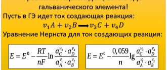
The English physicist and chemist Michael Faraday believed that if an electric current can magnetize a piece of iron, then the magnet must also somehow cause the appearance of an electric current. And he was right. In 1831 he discovered the phenomenon of electromagnetic induction.
Definition
Electromagnetic induction is a phenomenon consisting in the occurrence of an electric current in a conducting circuit, which is either at rest in a time-varying magnetic field or moves in a constant magnetic field in such a way that the number of magnetic induction lines penetrating the circuit changes.
Observing Spectra
In accordance with the density of magnetic field lines (MF), you can see the magnitude of the induction vector, and according to the direction of the force rows, its flow. Observation of the spectra of the direct current and the coil actually shows that when the conductor is removed, the MF induction decreases quite quickly.
The magnetic background is called:
- With different excretion at different points - heterogeneous. The inhomogeneous background is part of the linear and radial current, outside the solenoid, unchanged magnet, etc.
- With induction at all points - a uniform field. Graphically, such a MF is represented by lines of force, which are considered to be equally spaced parallel parts. This case is the background from inside the long solenoid, as well as the field between close adjacent flat tips of the electromagnet.
The product of the induction of the field penetrating into the circuit from its region is called the MI flux or the elementary MF. The definition was given and studied by the British physicist Faraday. He noted that this concept actually allows us to take a deeper look at the combined nature of magnetic and electrical phenomena.
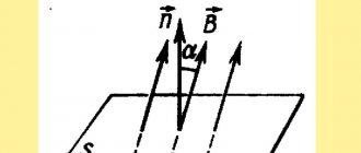
Denoting the flux by the letter f, the contour area S and the angle between the direction of the induction vector B and the normal part n to the region α, we can write the magnetic flux with the formula:
F = S cos α.
MP is a scalar dimension. For example, since the density of the force lines of a random magnetic field is equal to its induction, it is equalized by the entire number of lines that penetrate the circuit. As the field changes, the flow that permeates the circuit also changes.
The unit of magnetic flux is weber. The definition of an SI jet is considered to be a line whose area is 1 m², located on a uniform background with an induction of 1 W / m2 and perpendicular to the vector. This device will be designated:
1 W = 1 W/m2 – 1 m².
What is the phenomenon of electromagnetic induction?
In a general sense, the phenomenon of electromagnetic induction is the generation of electric current using a magnetic field.
Let's be more precise, the phenomenon of electromagnetic induction consists in the formation of an electromotive force (EMF) in a conductor as a result of a change in the flux of a magnetic field penetrating the surface surrounding the conductor. In a closed circuit, electromotive force (EMF) causes electric current to flow.
In the above definition of the phenomenon, two concepts may be unclear - induced emf and magnetic flux.
Induction emf.
The absolute value of the electromotive force (induction emf with the symbol εind) is the work of the external force Az, which causes the movement of a unit charge along the circuit. Therefore: | εind | = Az/q .
As you can see, in the definition we used the absolute value of the induced emf. This is because it can be negative in certain situations. On the other hand, the work of external forces, according to the principle of conservation of energy, must always be positive when generating electric current.
Determination of magnetic induction flux.
The flux of magnetic induction B through the surface S is called the scalar product of vectors B and S: dФ = B * S * cos α, where α is the angle between two vectors, and S is a vector perpendicular to the surface S with a value equal to the area of this surface.
The magnetic flux will change when any value included in the formula changes - surface area, magnetic induction value, angle between the surface area and the induction vector - while maintaining the constancy of other variables. Of course, all these quantities can change simultaneously, but in such a way that their product does not remain constant.
The fact that electric current is a source of a magnetic field has been known since 1820 (Orsted's work). Faraday wondered whether the opposite was also true—whether a magnetic field could be the source (cause) of an electric current. However, the matter turned out to be not so simple. It was not until 1831 that a scientist observed this phenomenon under certain special circumstances. It turned out that under stable conditions no electric current occurs.
Why is this happening? Even in a very strong, but time-constant magnetic field, electric current will not flow in a closed circuit “by itself.” It only flows when we move the circuit accordingly or change the magnetic field in which the circuit is located.
When Faraday turned his attention to the conditions under which an electric current arises in the presence of a magnetic field, he conducted dozens of experiments, which he generalized and from which he drew quantitative conclusions in the form of the law of electromagnetic induction. We will not talk about this law here, but will focus only on the essence of the phenomenon of electromagnetic induction. We will try to see the duality of this phenomenon, i.e. that it has two varieties, and answer the question why electric current flows under certain conditions.
We will consider what forces cause induced current, i.e. what forces act on free charges in a conductor, causing them to move.
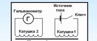
Faraday's 1831 experiment demonstrating electromagnetic induction between two coils (see Figure 1).
On the right is a battery that powers the smaller of the two coils (A), which creates a magnetic field. When this coil is at rest, no induced current is observed. However, if you move it inside a larger coil (B), the alternating magnetic flux induces a current in it. We discover this by observing the oscillations of the galvanometer needle (G) on the left.
Rice. 1. Faraday's 1831 experiment demonstrating electromagnetic induction between two coils (see Figure 1). Source: J. Lambert, Wikimedia Commons)
Features of the flow
The rate of change of the magnetic flux generates an electronic background that has closed power supplies (vortex field). This background is considered in the conductor as the circulation of external forces. This phenomenon is called electrical induction, and the power that can be determined generated in this case is the induced emf of the surface .
The flux highlights the likelihood of characterizing the entire magnet or types of other MF sources. If induction brings to the fore the probability characteristic of its effect at any particular point, the flow will be whole. This is the second most important feature of the field. If the MI functions as the power part of the MP, the flow is considered its energy line.
Returning to the experiments, we can say that virtually any electromagnetic coil can be considered as 1 closed. This is the circuit along which the magnetic flux of the induction vector will flow, then the current of MI electrons will be noticed during flux linkage.
Thus, directly under the action of the jet, an electronic background is formed in a closed conductor. And during this time it will generate current.
Magnetic induction
According to progressive scientific ideas about electrical phenomena, MF is inextricably linked with current and cannot be present without it . It is impossible to assume electric current without MF. Including in the case of a permanent magnet, this background is associated with molecular lines.
If a needle is placed in the place where the MP is located, it tends to borrow a certain state, which actually shows the orientational qualities of the MP. The coordinated direction at this place point must take into account the destination, where the axis is mounted - a freely suspended infinitesimal magnetic needle whose middle is aligned with the starting place point. In this case, out of 2 possible directions along the axis of the MP arrow, the assignment from the southern end to the north is symbolically assigned.
You can get a clearer idea of the direction of the field if there is a series of lines where the axes of all the arrows are relatively tangent. These parts are called magnetic lines.
A set of rows is referred to as MP. If we infinitely reduce the area of the contour, attracting it to a point, we can come to the expression for the infinitesimal stage d, T is active in the contour of the small region s, where the angle P has a specific value between the normality to the plane and the small contour. In this case, the direction of the field will be the point where the small outline is located.
Impact on a flat circuit with current
Under such conditions, coefficient B is taken as a characteristic of the MF intensity at this location point and is called the MF induction. It is considered a quantity that combines the purpose of the MI vector with the direction of the magnetic field at this point in place.
An MF characterized in some areas by the same value of the MF vector is called a uniform MF. Induction in the international system (SI) is measured in units of Tesla (TL). The MI of a homogeneous MF is 1 t if it acts on a flat electron sequence with an area of 5 '= 1 m and a current of 7 = 1 A, located so that the magnetic lobes lie in the plane of the circuit p = 0.5 n sin p = 1 with a coefficient t = 1 Nm.
The area of location of any part that is associated with a specific vector is called a field. The concept of strings is widely used to visually represent VIs. In the case of a linear field, you can see a line, since the vector itself is oriented tangentially at any point. The tubular line is the area of the node, limited by the abundance of adjacent rows made through the closed outline. The vector field representation is often used to describe various body interactions. In particular, in the MP display, the background of the magnetic induction vector is mentioned, which defines the parts and tubes of the MP in it.
ELECTROMAGNETISM
BASIC CONCEPTS AND LAWS
1. Magnetic field induction. Interaction of currents
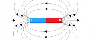
Forces act on a magnetic needle placed near a current-carrying conductor, as a result of which the needle is set in a certain direction.
The forces that cause the magnetic needle to turn are called magnetic.
If the action of magnetic forces is detected in space, then they say that there is a magnetic field in it.
Current-carrying conductors and magnets are always surrounded by a magnetic field.
A magnetic field does not affect stationary electric charges.
For the direction of the magnetic field
take the direction of the force acting on the north pole of a magnetic needle placed at a given point in the field.
A current-carrying conductor placed in a magnetic field is also subject to a force. The magnitude of this force is determined by Ampere's law:
(1)
where Dl is the short length of the conductor, b is the angle between the directions of the magnetic field and the current in the conductor; i,
D l
and
B
are expressed in the same system of units;
the product i* D l
is called
the current element.
Value B,
included in relation (1), characterizes the magnitude and direction of the magnetic field and is called
the magnetic field induction.
The magnetic field induction is numerically equal to the force with which the magnetic field acts on a unit current element ( i* D l
= 1), located perpendicular to the direction of the field.
Magnetic field induction is a vector quantity. The direction of the magnetic induction vector coincides with the direction of the magnetic field. Magnetic induction depends on the properties of the medium.
The SI unit for measuring induction is the tesla (t).
1 tesla is the induction of a field that acts on a unit current element
i* D l
= 1
A*m,
located perpendicular to the field, with a force of 1
N
perpendicular to the field, with a force of 1 dyne;
The induction of a magnetic field in a vacuum is called magnetic field strength.
To determine the magnetic field strength, it is necessary to remove matter from the space in which there is a field, and then measure the force acting on a unit element of current ( i* D l
= 1), located perpendicular to the direction of the field.
The magnetic field strength does not depend on the properties of the medium, but is determined only by the current strength and the shape of the conductor.
The ratio is called absolute magnetic permeability
environment.
The numerical value m' is expressed in relative units (relative to the absolute value of the vacuum magnetic permeability m0). The quantity is called relative magnetic permeability
(or simply magnetic permeability). It does not depend on the choice of unit system.
The direction of the force acting on a current-carrying conductor is determined by the left-hand rule
: if you position the palm of your left hand so that the magnetic field lines enter it, and the extended fingers indicate the direction of the current, then the extended thumb will indicate the direction of the force acting on the conductor (Fig. 1).
Two sufficiently long straight and parallel conductors with current interact with each other in such a way that if the currents have the same direction, then they attract, and if they are opposite, then they repel.
The mathematical expression of this law (Ampere’s law) has the following form:
(in SI system), (1.2)
where a
is the distance between the conductors, l is the length of the conductors, i1, i2 are the current strengths in them, m is the magnetic permeability of the medium.
A moving charge in a magnetic field is acted upon by a force (called the Lorentz force)
(1.3)
where e
is the charge of the particle,
v
is the velocity, a is the angle between the direction of the velocity and the induction
B.
The Lorentz force is directed perpendicular to the plane in which the vectors
B
and
v lie.
3. Strength of magnetic fields of currents
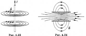
Magnetic field lines
These are called lines whose tangents coincide with the direction of the intensity of this field at a given point. Magnetic field lines are closed (unlike electrostatic field lines); such fields are called vortex fields.
Linear current lines of force are concentric circles lying in a plane perpendicular to the conductor (Fig. 2). The direction of the magnetic field line is determined by
the right screw rule
: if the screw is turned so that it moves progressively in the direction of the current, then the direction of rotation of its head will coincide with the direction of the field lines (Fig. 3-4).
Rice. 3. Magnetic field lines of circular current, detected by the action of the field on iron filings.
Rice. 4. Magnetic field lines of the solenoid, detected by the action of poly on iron filings.
The magnetic field induction created by the current element i
D l is
equal to
, (1.4)
where r is the distance from the current element to the point at which the voltage is determined, a is the angle between i* D l
and
r.
This relationship is called
the Biot
-
Savart
-
Laplace
.
Magnetic field induction of a straight long wire with current:
(1.5)
where a -
the distance from the conductor to the field point at which the strength is determined.
Magnetic field induction at the center of the circular current:
(1.6)
where R
— radius of the turn.
Magnetic induction of the field created by a segment of a straight conductor (figure),
The SI unit of magnetic field strength is ampere per meter (a/m)
Total current law for magnetic field in vacuum
(theorem on the circulation of the magnetic induction vector)
where is the vector of the elementary length of the contour, directed along the traversal of the contour;
— component of the magnetic induction vector in the direction of the tangent of the contour L of arbitrary shape; — magnetic constant; - algebraic sum of currents covered by the circuit.
Magnetic field induction inside a solenoid (in vacuum) having N turns and length I,
Magnetic field induction inside a toroid (in vacuum)
Magnetic induction vector flux (magnetic flux) through an elementary area
where Bn is the projection of the magnetic induction vector onto the direction of the normal to the area dS.
Magnetic flux through a flat circuit of area S in the case of:
a) inhomogeneous field
b) uniform field
where is the angle between the normal vector to the contour plane and the magnetic induction vector;
Bn is the projection of the magnetic induction vector onto the normal. Flux linkage, i.e. total magnetic flux coupled to all N turns of the solenoid or toroid,
where Fv is the magnetic flux through one turn.
For solenoid
where μ is the magnetic permeability of the medium.
Work when moving a current-carrying conductor in a magnetic field. Electromagnetic induction
When a conductor moves in a magnetic field, work is done
(1.7)
where F1 is the magnetic flux through the current loop at the beginning of the movement, F2 is the magnetic flux at the end of the movement.
Magnetic flux
through any contour (in a uniform field) is called the product of magnetic induction
B
by the area of this contour S and by the cosine of the angle o between the direction of the field and the normal to the surface of the contour (Fig. 5):
(1.8)
The unit of magnetic flux in the SGSM system is maxwell (μs), in
SI system - Weber (wb).
A changing magnetic flux excites an electric field with closed lines of force (vortex electric field). In a conductor, the induced field manifests itself as the action of external forces. This phenomenon is called electromagnetic induction ,
and the electromotive force that arises is
the induced emf .
Currents that are caused by induced emf are called induction .
The induction current has such a direction that its magnetic field prevents changes in the magnetic field that caused the appearance of the induction current (Lenz's law).
The magnitude of the electromotive force of induction can be calculated by the formula
(1.9)
Thus, the induced emf is equal to the rate of change of the magnetic flux through the area limited by the contour. The minus sign indicates the direction of the EMF (in accordance with Lenz's law).
Self-induction
With any change in current in the conductor, an induced emf occurs, which is excited by the magnetic flux of this current. This phenomenon is called self-induction.
The self-induction emf can be found from the formula
(1.10)
where L is the self-induction coefficient, or inductance, Di/Dt is the rate of change of current.
L depends on the shape and size of the conductor and on the properties of the medium.
The SI unit of inductance is the henry (h).
1 henry is the inductance of a conductor in which, when the current changes by 1 ampere in 1 second, a self-inductive emf equal to 1 volt occurs;
Magnetic field energy around a current-carrying conductor:
(1.11)
In space where there is a magnetic field, energy is distributed. The energy density of a uniform magnetic field (energy per unit volume) is determined by the formula
(1.12)
Electromagnet lifting force:
(1.13)
where S is the cross-sectional area of the electromagnet tip, m0 is the magnetic permeability of air (close to 1).
Eddy currents
(or
Foucault currents)
are induced currents that arise in massive conductors placed in a changing magnetic field.
Magnetic properties of matter
Magnets
are substances that can be magnetized. Magnets, when magnetized, create a magnetic field in the surrounding space.
The degree of magnetization of a magnet is determined by the magnetization vector
I, which is proportional to the vector of the field strength created by the magnet.
Magnetic induction B
is a vector quantity equal to the average value of the field induction inside the magnet. This value is the sum of the field induction created by the magnetizing current (m0H) and the field induction created by the magnet (4pI)
(1.14)
where m0 is the magnetic permeability of the void.
The relationship between the magnetization vector I and the magnetizing field strength is established by the formula
(1.15)
where is the quantity c, called magnetic susceptibility ,
depends on the type of magnet and its condition (temperature, etc.). Since B=mH, then
(1.16)
Substances for which m.>1 (but not significantly) are called paramagnetic
(or
paramagnetic),
and substances with m.<1 are
diamagnetic
(or
diamagnetic).
Substances in which m is much greater than unity are called
ferromagnets.
Ferromagnets
differ from paramagnetic materials in a number of properties.
a) Magnetization curve,
expressing the relationship between
H and B,
for paramagnets it is direct, for ferromagnets it is complex
Thus, for paramagnetic substances;" - the value is constant, for ferromagnets it depends on the field strength.
b) The magnetic susceptibility of ferromagnets changes with temperature in a complex way: at a certain temperature Tk. called temperature
(Curie point),
the ferromagnetic properties disappear: the ferromagnet turns into a paramagnet.
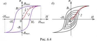
c) When a ferromagnet is magnetized, a peculiar lag in the change in induction occurs from changes in the field strength. This phenomenon is called hysteresis,
and the curve depicting the dependence
of B
on
H
during magnetization reversal is called
a hysteresis loop
(Fig. 6).
Rice. 6. Pearl of hysteresis. 01 – magnetization curve from a demagnetized state, 123 – demagnetization curve
When reversing magnetization in one cycle, we are consumed. Energy proportional to the area of the hysteresis loop. Residual magnetic induction
Br
is the amount of induction that remains in a ferromagnet after the field is removed
( H = O).
Coercive tension,
or
coercive force ( HC)
, the magnitude of the magnetic field strength in which a ferromagnet must be placed in order to remove the residual induction (in the direction this field must be opposite to the residual induction).
Magnetic saturation ( IS
- the highest value of magnetization I. If a ferromagnet is magnetized to saturation, then a further increase in the field practically does not change the value of magnetization. Magnetic saturation is measured in gauss.
The initial magnetic permeability
mН
is the limiting value of magnetic permeability when the field strength and induction are close to zero, i.e.
The properties of ferromagnets are explained by the presence in them of regions that, in the absence of an external magnetic field, are spontaneously magnetized to saturation. These areas are called domains.
But the location and magnetization of these regions are such that in the absence of a field the total magnetization of the entire body is zero.
When a ferromagnet is in a magnetic field, the boundaries between domains shift (in weak fields) and the magnetization vectors of the domains rotate in the direction of the magnetizing field (in stronger fields), resulting in the ferromagnet becoming magnetized.
A ferromagnet placed in a magnetic field changes its linear dimensions, i.e., it is deformed. This phenomenon is called magnetostriction.
The relative elongation depends on the nature of the ferromagnet and the magnetic field strength.
The magnitude of the magnetostriction effect does not depend on the direction of the field; Some substances experience shortening (nickel), others elongation (iron in weak fields) along the field. This phenomenon is used to produce ultrasonic vibrations with frequencies up to 100 kHz.
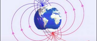
Earth's magnetic field
The earth is surrounded by a magnetic field. The line passing through those points on the Earth's surface at which the strength of this field has a horizontal direction is called the magnetic equator.
Points on the Earth at which the magnetic field strength has a vertical direction are called magnetic poles.
There are two such points on Earth: the north magnetic pole (in the southern hemisphere) and the south magnetic pole (in the northern hemisphere).
The magnetic field strength at the magnetic equator is about 0.34 Oe, at the magnetic poles - about 0.66 Oe. In some areas (in the so-called areas of magnetic anomalies)
tensions rise sharply. In the area of the Kursk magnetic anomaly it reaches 2 Oe.