Vortex field
A careful study of the magnetic field using magnetic induction lines allows us to establish a very important feature of it. Magnetic induction lines have neither beginning nor end. They are always closed.
Let us remember that with an electrostatic field the situation is different. Electrostatic field strength lines begin at positive charges and end at negative charges.
Fields with closed lines of force are called vortex fields. The magnetic field is a vortex field.
The closure of magnetic induction lines is a fundamental property of a magnetic field. It lies in the fact that the magnetic field has no sources. No magnetic charges similar to electric ones were detected.
Note that neither the laws of electrodynamics nor any other known physical laws prohibit the existence of magnetic charges; more precisely, the existence of particles with magnetic charges. Therefore, searches for such particles have been and are being undertaken. However, they have not yet been successful. The reason for this is not yet clear.
Magnetic induction lines
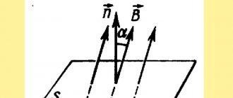
Magnetic induction lines are lines whose tangents are directed in the same way as the vector at a given point in space (Fig. 4.22).
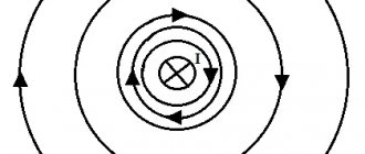
Let's construct magnetic induction lines for the magnetic field of a straight conductor carrying current. From the previous descriptions of experiments with a contour and a magnetic needle, as well as from considerations of symmetry, it follows that the lines of magnetic induction in this case are concentric circles lying in a plane perpendicular to this current-carrying conductor. The center of the circles is on the axis of the conductor (Fig. 4.23). As in the case of electric field strength lines, magnetic induction lines can be arranged to be drawn so that their density characterizes the magnitude of vector B in a given location. In Figure 4.23, the concentric circles are condensed towards the center. This should mean that the magnetic induction near the wire is greater than far from it.
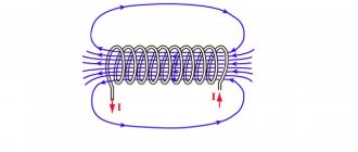
The picture of the magnetic induction lines of a current-carrying coil (solenoid) is shown in Figure 4.24 (the solenoid is shown in section). If the length of the solenoid is much greater than its diameter, then the field inside the solenoid can be considered uniform. The lines of magnetic induction of such a field are parallel, their density is the same everywhere.
The pattern of magnetic induction lines can be made visible by using fine iron filings. In a magnetic field, each piece of iron sprinkled on a sheet of cardboard becomes magnetized and behaves like a small magnetic needle. The presence of such a large number of arrows makes it possible to determine the direction of the magnetic induction vector of the magnetic field at a large number of points and, therefore, more accurately determine the location of the induction lines. Some of the magnetic field patterns are shown in Figures 4.25-4.28.
mozok.click
The pattern of magnetic lines can be reproduced using iron filings.
Let's take a horseshoe magnet, put a plexiglass plate on it and pour iron filings onto the plate through a strainer. In a magnetic field, each piece of iron will be magnetized and turn into a small “magnetic needle”. Improvised “arrows” are oriented along the magnetic lines of the magnet’s magnetic field (Fig. 2.4).
Draw a picture of the magnetic field lines of a horseshoe magnet.
Let's learn about a uniform magnetic field
A magnetic field in a certain part of space is called uniform if at each point the magnetic induction vectors are the same both in magnitude and in direction (Fig. 2.5).
In areas where the magnetic field is uniform, the magnetic induction lines are parallel and located at the same distance from each other (Fig. 2.5, 2.6). Magnetic lines of a uniform magnetic field directed towards us are usually depicted as dots (Fig. 2.7, a) - it is as if we see “arrowheads” flying towards us. If magnetic lines are directed away from us, then they are depicted with crosses - it’s as if we see the “feathers of arrows” flying away from us (Fig. 2.7, b).
In most cases, we are dealing with a non-uniform magnetic field - a field at different points of which the magnetic induction vectors have different values and directions. The magnetic lines of such a field are curved, and their density is different.
Rice. 2.6. The magnetic field inside a strip magnet (a) and between two magnets facing each other with opposite poles (b) can be considered uniform
Studying the Earth's magnetic field
To study terrestrial magnetism, William Gilbert made a permanent magnet in the form of a ball (model of the Earth). Having placed a compass on the ball, he noticed that the compass needle behaves in the same way as on the surface of the Earth.
Experiments allowed the scientist to suggest that the Earth is a huge magnet, and its south magnetic pole is located in the north of our planet. Further research confirmed W. Gilbert's hypothesis.
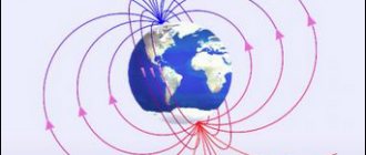
In Fig. Figure 2.8 shows a picture of the magnetic induction lines of the Earth's magnetic field.
rice. 2.7. Image of magnetic induction lines of a uniform magnetic field, which are perpendicular to the plane of the drawing and directed towards us (a); directed from us (b)
Imagine that you are walking towards the North Pole, moving exactly in the direction that the compass needle is pointing. Will you reach your destination?
The magnetic induction lines of the Earth's magnetic field are not parallel to its surface. If you fix the magnetic needle in a gimbal, that is, so that it can rotate freely both around the horizontal and
Rice. 2.8. Layout of magnetic lines of the magnetic field of planet Earth
and around the vertical axes, the arrow will be set at an angle to the surface of the Earth (Fig. 2.9).
How will the magnetic needle be located in the device in Fig. 2.9 near the Earth's north magnetic pole? near the Earth's south magnetic pole?
The Earth's magnetic field has long helped travelers, sailors, military personnel and others to navigate. It has been proven that fish, marine mammals and birds orient themselves according to the Earth’s magnetic field during their migrations. Some animals, such as cats, also navigate when looking for the way home.
Learn about magnetic storms
Studies have shown that in any area the Earth's magnetic field changes periodically, every day. In addition, small annual changes in the Earth's magnetic field are observed. However, there are also sudden changes. Strong disturbances in the Earth's magnetic field, which cover the entire planet and last from one to several days, are called magnetic storms. Healthy people practically do not feel them, but for those who have cardiovascular diseases and diseases of the nervous system, magnetic storms cause a deterioration in their well-being.
The Earth's magnetic field is a kind of “shield” that protects our planet from charged particles flying from space, mainly from the Sun (“solar wind”). Near the magnetic poles, streams of particles fly quite close to the Earth's atmosphere. With increasing solar activity, cosmic particles enter the upper layers of the atmosphere and ionize gas molecules - auroras are observed on Earth (Fig. 2.10).
Let's sum it up
Magnetic induction B is a vector physical quantity that characterizes the force action of a magnetic field. The direction of the magnetic induction vector coincides with the direction to which the north pole of the magnetic needle points. The SI unit of magnetic induction is tesla (T).
Conditional directed lines, at each point of which the tangent coincides with the line along which the magnetic induction vector is directed, are called magnetic induction lines or magnetic lines.
Magnetic induction lines are always closed, outside the magnet they leave the north pole of the magnet and enter the south pole, and are denser in those areas of the magnetic field where the magnetic induction module is greater.
Planet Earth has a magnetic field. Near the Earth's north geographic pole is its south magnetic pole, and near its south geographic pole is its north magnetic pole.
Control questions
1. Define magnetic induction. 2. What is the direction of the magnetic induction vector? 3. What is the SI unit of magnetic induction? Who is it named after? 4. Give the definition of magnetic induction lines. 5. What direction is accepted as the direction of magnetic lines? 6. What determines the density of magnetic lines? 7. What magnetic field is called uniform? 8. Prove that the Earth has a magnetic field. 9. How are the Earth’s magnetic poles located relative to the geographic ones? 10. What are magnetic storms? How do they affect a person?
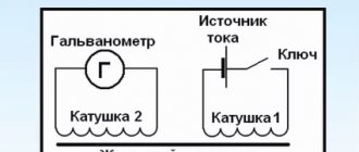
How does induced emf and induced current occur?
As I said in previous articles, an electromagnetic field arises around a conductor through which electric current flows. I reviewed this magnetic field here and here. However, there is also the opposite phenomenon, which is called electromagnetic induction. This phenomenon was discovered by the English physicist M. Faraday.
To consider this phenomenon, consider the following figure
This figure shows a frame made of a conductor placed in an electric field with induction B. If this frame is moved up and down in the direction of the magnetic lines of force or left and right perpendicular to the lines of force, then the magnetic flux Φ penetrating the frame will be almost constant. If you rotate the frame around the O axis, then over a certain period of time ∆t the magnetic flux will change by a certain amount ∆Φ and as a result, an induced emf Ei will appear in the frame and a current I, called the induced current, will flow.
Information about magnetic induction lines
From the data presented, the force nature of the field created by alternating current or the movement of a conductor is clear. A vector expression is used to accurately express the effects on the indicator element. At the beginning of publication, such a component was the compass needle. The following shows the possibility of using a conducting frame with current.
Magnetic field lines are used to visually depict this phenomenon. If at any point of such a curve you draw a vector (B) along a tangent, it will indicate the direction of influence. Size to scale shows a certain strength.
By simply checking the geometric parameters, you can establish the uniqueness of each vector. They, like the lines of the force field, do not intersect. Below are methods for clarifying the distribution of energy flows in the conductor and the surrounding space.
Two ways to determine the direction of a force field (electric current)
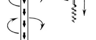
For the version with a straight conductor, the right hand is squeezed as shown in the first figure. The thumb is directed in the direction of current flow. Clenched fingers will show the direction of the lines of force. The second part of the picture demonstrates the determination of field parameters when passing current through a ring frame - the “gimlet rule”. The rotation of this tool is similar to the direction of the current.
For your information. If the solenoid is long enough, the field will be uniform over most of the working volume. It is acceptable to assume that the magnetic field lines in this case are located parallel.
Direction of magnetic induction
Magnetic forces, like any other forces, have a direction. To determine it, special rules are used.
Gimlet rule
According to this rule, if the direction of translational movement of the tip of the gimlet when screwing in coincides with the direction of the current in the conductor, then the direction of the rotational movement of the gimlet at each point coincides with the direction of the magnetic field induction vector.
Rice. 2. The gimlet rule.
Right hand grip rule
The above rule is often not clear enough due to the fact that the gimlet is used infrequently in the modern world. Therefore, it is much more convenient to apply the rule of coverage with the right hand: if the thumb of the right hand indicates the direction of the current, then the remaining fingers will indicate the direction of the magnetic lines.
This rule is also more convenient because it can also be used to determine the direction of the magnetic induction of a coil with current, in this case four fingers are directed along the turns of the coil, in the direction of the current in them, and the thumb will indicate the direction of the magnetic induction vector. That is, in both cases the thumb points to a straight line, and the rest of the fingers point to the encircling line.
Rice. 3. Right hand grip rule.
Magnetic lines of straight wire with current
We use the same experimental scheme for a straight wire through which electric current flows. In this case, you can replace the transparent plate with a piece of cardboard or plywood.
Rice. 3. Magnetic lines of a straight wire with current.
The sawdust can be seen to line up in concentric circles, showing the shape of the magnetic lines. When the direction of the current changes, the filings rotate by 1800. Consequently, the direction of the magnetic lines in this case is related to the direction of the current in the conductor.
It is known that the Earth is a huge “strip” magnet. Thanks to this, with the help of a magnetic compass needle we can navigate in space. But we must keep in mind that there are places with large deposits of magnetites (iron ores), which create a strong “background” magnetic field, which turns the compass needle along its magnetic lines. One of these places is the Kursk magnetic anomaly, located in the Kursk region of our country.
What is magnetic flux?
Magnetic flux is a physical quantity proportional to the number of magnetic field lines in a certain area of space. Since lines of force are an abstract concept, therefore, magnetic flux characterizes the intensity of the magnetic field, that is, magnetic induction in a given area. Magnetic flux is denoted by Ф and has the dimension Wb (Weber).
Thus, the magnetic flux can be expressed by the following expression
where B is magnetic induction,
S – surface area for which the magnetic flux is calculated.
The figure shows magnetic field lines that are perpendicular to surface S, that is, the angle between the magnetic induction vector B and surface S is 90°. However, it often happens that it is necessary to calculate the magnetic flux on a plane not perpendicular to the magnetic induction vector. To determine such a magnetic flux, it is necessary to bring the magnetic induction vector to the normal
Thus, the final expression for finding the magnetic flux will have the form
where B is the magnetic induction vector,
S is the surface area on which the magnetic flux is found,
α is the angle between the magnetic induction vector and the normal to the surface S.
General information
Back in the 19th century, it was established that the directed movement of elementary charge carriers leads to the appearance of electric current. The charges, interacting with each other, cause the appearance of a force called an electromagnetic field. That is, two phenomena arise around any charged body: magnetic and electric.
The first, unlike the second, is possible only with the movement of an electric charge. Even if it is created by a permanent magnet, it is still caused by the movement of particles. At its core, a magnetic field is a force characterized by a moment. She has energy. Any change in the electric field leads to a disturbance in the magnetic field. Moreover, this statement is true and vice versa.
The main characteristic of force is the induction vector. It is used to determine the effect of a magnetic field at a point in space. That is, the parameter shows with what force the charge q is influenced moving at speed V. This is a vector quantity formula for calculation, which has the form: F = q *V * sin (a) , where a is the value of the angle between the velocity vector and the magnetic induction. In this case, the direction of the force can be determined using the gimlet rule. It will always be directed perpendicular to the velocity vector. The SI unit of measurement is the tesla (T).
The magnetic field is characterized by the following:
- When its value is constant, the dipole is affected by a torque: N = . Just as the compass needle turns along the action of the field, so the coil through which the current flows tends to take a position in which its plane will be parallel to the lines of induction.
- The occurrence of induction leads to the fact that the trajectory of the charge carrier takes on a spiral shape. This effect manifests itself in the distribution of electrical particles over the cross section of the conductor.
- The time-varying field causes the charges to move, and the resulting current counteracts the further inconstancy of the force over time.
- The force acting in the magnetic field moves the dipole in the direction of the gradient. This occurs due to the division of the influence in a heterogeneous system into two beams.
The magnetic field represents matter. It is determined by the properties of the substance. From the point of view of quantum mechanics, this is a special case of electromagnetic interaction. To depict it, imaginary segments are used. These are magnetic field lines that are represented as closed directional curves.
Magnetic induction lines
A clear picture of the magnetic field can be obtained by constructing the so-called magnetic induction lines. Magnetic induction lines are lines whose tangents at any point coincide with the vector at a given point in the field (Fig. 1.10). The lines of the magnetic induction vector are similar to the lines of the electrostatic field strength vector.
For the magnetic field of a straight conductor with current, from the previous experiments it follows that the lines of magnetic induction are concentric circles lying in a plane perpendicular to this conductor with current (see Fig. 1.9). The center of the circles is on the axis of the conductor. The arrows on the lines indicate in which direction the magnetic induction vector tangent to a given line is directed.
Figure 1.11 shows the magnetic field pattern of a current-carrying coil (solenoid). If the length of the solenoid is much greater than its diameter, then the magnetic field inside the solenoid can be considered uniform
.
The magnetic induction lines of such a field are parallel
and located at equal distances from each other.
Figure 1.12 shows the Earth's magnetic field. The Earth's magnetic field lines are similar to the magnetic field lines of a solenoid. The magnetic north pole N is close to the geographic South Pole, and the magnetic south pole S is close to the geographic North Pole. The axis of such a large magnet makes an angle of 11.5° with the axis of rotation of the Earth. Periodically, the magnetic poles change their polarity. The last such replacement occurred about 30,000 years ago.
The pattern of magnetic induction lines can be made visible by using fine iron filings. You are already familiar with this method.
In a magnetic field, each piece of iron poured onto a sheet of cardboard becomes magnetized and behaves like a small magnetic needle. A large number of such arrows allows you to determine the direction of the magnetic field at a larger number of points and, therefore, more accurately determine the location of the magnetic induction lines. Examples of magnetic field patterns are shown in Figures 1.13—1.16.
Magnetic field lines
The electric field can be studied using elementary charges, by the behavior of which it is convenient to judge the meaning and direction of matter. An analogue of such energy is a test particle, which can be represented as an arrow, or rather a compass. For example, if you take many devices that point to the Earth's magnetic poles and place them in some geometric space, you can visualize the forces that characterize the electromagnetic field.
But it is possible to determine the direction of matter around conductors carrying currents of various shapes, or the so-called magnetic spectrum. Various settings are used for this. The simplest of them is a complex that includes:
- power supply;
- dielectric frame;
- a thick copper wire capable of carrying a current of about 20 amperes;
- iron filings.
A wire is passed through a drilled hole in the frame and connected to a power source. Chips are poured on top of the wire. After applying current, it will be possible to observe how chains are formed, repeating the shape of the propagation of the field force. For example, around a straight wire located perpendicular to the plate, you will see ring lines of force.
By conducting an experiment, you can find out what the peculiarity of magnetic induction lines is. Firstly, their distribution is uneven. In some places they are thicker. Secondly, these lines never intersect and are always closed. From a physics point of view, we can add that the direction of the magnetic field can be determined using the gimlet rule. In this case, the induction vector is tangent to each point of the segment.
It should be noted that the field, albeit a constant one, can be explored using a conventional magnet and a compass.
To experiment, you need to pour sawdust onto a sheet of paper and place a compass next to it. Then slowly bring the magnet from below, preferably through a layer of wood. Then it will be possible not only to see the pattern of the field, but also to notice that the compass needle points in the same direction where the iron filings are directed.
Vortex field
Fields with closed vector lines are called vortex fields. The magnetic field is a vortex field.
The closure of magnetic induction lines is a fundamental property of a magnetic field. It lies in the fact that the magnetic field has no sources. Magnetic charges similar to electric ones do not exist in nature.
The magnetic field is a vortex field; at each point in the field, the magnetic induction vector has a certain direction. This direction is indicated by a magnetic needle or can be determined by the gimlet rule. The magnetic field has no sources; magnetic charges do not exist in nature.
Questions for the paragraph
1. How are a closed loop with current and a magnetic needle oriented in a uniform magnetic field?
2. What are magnetic induction lines called?
3. What fields are called vortex fields?
4. How does a vortex field differ from a potential field?
Basic features and properties of magnetic lines
A magnetic field exists around permanent magnets (bar, arc, or other shapes) and around a metal wire carrying an electric current.
The magnetic field is depicted in the form of magnetic lines or magnetic induction lines. A magnetic induction line is a kind of geometric curve, at any point of which the vector (direction) of magnetic induction is directed tangentially to it.
can be identified :
- The magnetic lines are continuous;
- Magnetic lines are always closed. This means that in nature there are no separate magnetic charges by analogy with electric charges. Researchers have long tried to find this charge by reducing (crushing) the size of permanent magnets. But even the most microscopic magnet always has two poles: north and south;
- The direction of magnetic lines depends on the direction of electric current;
- The thickness (density) of the lines corresponds to the field value: the denser the lines are, the greater the field value.
Non-potential nature of magnetic forces
The closedness of the magnetic field lines means that the work of magnetic forces on a closed path may not be equal to zero. Magnetic forces, unlike electrostatic ones, are non-potential.
The non-potential nature of magnetic forces is clearly manifested in the rotation of a current-carrying conductor in the field of a permanent magnet. For the first time such rotation (the prototype of a modern electric motor) was carried out by Faraday a year after Oersted's discovery.
Faraday lowered the ends of a suspended U-shaped conductor into a trench with mercury. A magnet passed vertically through the trench from below so that one of its poles protruded above the mercury.
Due to this, the current-carrying conductors were in the magnetic field of one pole of the magnet. When current was passed through the mercury and the conductor, the latter began to rotate around the magnet. Figure 4.29 shows a working model of a Faraday installation.
This experiment demonstrates another remarkable property of magnetic interactions - its non-central nature. The pole of a magnet does not attract or repel current-carrying conductors, but causes them to rotate around itself. The force acting from the magnet is not directed along the line connecting the magnet pole with individual sections of the current-carrying conductor.
Vector direction
You can clearly demonstrate the magnetic field lines if you spread small iron filings evenly (in one layer) on a glass sheet through which a current-carrying conductor is passed. After turning on the current, the filings are magnetized, that is, they acquire the properties of magnetic needles and are installed along the field lines. Thus, the result of the action of a magnetic field on magnetic needles (iron filings) or a frame with current can be used to determine the direction of the magnetic induction vector.
Rice. 2. Demonstration of magnetic field lines from a straight wire with current using iron filings.
The direction of the magnetic induction vector is usually considered to be the direction from the south pole S to the north pole N of the magnetic needle, which is oriented unhindered and established in the magnetic field.
This direction coincides with the direction of the positive normal (perpendicular) to the closed loop with current. To determine this direction, the “gimlet rule” is used, which sounds like this: the vector is directed in the direction where the gimlet handle (with a right-hand thread) would move if it were screwed in in the direction of the current in the frame (or in the wire).
A visual (graphic) representation of the magnetic field is obtained by drawing the so-called magnetic induction lines. A line at any point of which the magnetic induction vector is directed tangentially is called a magnetic induction line or a magnetic induction intensity line. The picture of the magnetic induction lines for the permanent magnets, the current frame and the coil can be made visible by again using fine iron filings as in the case of a straight wire.
Rice. 3. Magnetic induction lines of coils, frames with current, permanent magnets.
Research has shown that magnetic induction lines are always closed, unlike electric field lines. From this fundamental property it follows that in nature there are no magnetic charges similar to electric ones. A magnetic field arises (induced) from moving electric charges or from an alternating electric field.
What is the induced emf?
To determine the magnitude of the resulting EMF, consider a circuit placed in a uniform magnetic field with induction B; a conductor of length l can move freely along this circuit.
Under the influence of force F, the conductor begins to move with speed v. In some time ∆t the conductor will travel the path db. Thus, the work expended on moving the conductor will be
Since the conductor consists of charged particles - electrons and protons, they also move along with the conductor. As is known, a moving charged particle is acted upon by the Lorentz force, which is perpendicular to the direction of motion of the particle and to the magnetic induction vector B, that is, electrons begin to move along the conductor, leading to the emergence of an electric current in it.
However, a conductor with current in a magnetic field is subject to a certain force Ft, which, in accordance with the left-hand rule, will be opposite to the action of the force F, due to which the conductor moves. Since the conductor moves uniformly, that is, at a constant speed, the forces Ft and F are equal in absolute value
where B is the magnetic field induction,
I is the current strength in the conductor arising from the action of induced emf,
l is the length of the conductor.
Since the path db traversed by the conductor depends on the speed v and time t, the work spent on moving the conductor in the magnetic field will be
When a conductor moves in a magnetic field, almost all the mechanical energy expended on this work is converted into electrical energy, that is
Thus, transforming the last expression, we obtain the value of the induced emf when a straight conductor moves in a magnetic field
where B is the magnetic field induction,
l – conductor length,
v is the speed of movement of the conductor.
This expression corresponds to the movement of the conductor perpendicular to the lines of magnetic induction. If movement occurs at a certain angle to the lines of magnetic induction, then the expression takes the form
In practice, it is quite difficult to calculate the speed of movement of the conductor, so we transform the expression to the following form
where dS is the area that the conductor crosses during its movement,
dΦ – magnetic flux penetrating the area dS.
Thus, the induced emf is equal to the rate of change of the magnetic flux that penetrates the circuit.
To indicate the direction of current movement in the circuit, a “–” sign is introduced, which indicates that the current in the circuit is directed against the positive bypass of the circuit. Thus
Often a circuit consisting of many turns of wire moves in a magnetic field, so the induced emf will have the form
where w is the number of turns in the circuit,
dΨ = wdΦ – elementary flux linkage.
To paraphrase the previous definition, the induced emf in a circuit is equal to the rate of change in the flux linkage of this circuit.
Image of magnetic induction lines
To visually study the distribution of the field in space, the dimensions of the measuring elements are reduced. Iron filings evenly scattered on the surface of a cardboard sheet or other electrically neutral plane are suitable for the experiment.
If you bring a magnet from the reverse side, metal particles, like miniature compass needles, are distributed along the force strips. By the distance between them one can judge the energy parameters of the field in a certain place. Create a drawing in the same way. Greater density (near the poles) indicates an increased value of induction.
For your information. Physically separating a permanent magnet into parts will not create separate poles. This is a fundamental difference from electrostatic charges of a certain polarity, which also create a force field.
The presented knowledge is used to solve various engineering problems. In particular, simple rules for determining the direction of current in a conductor and the direction in which the solenoid core moves are useful.
Magnetic levitation train accelerates to high speeds with minimal energy losses
Application of magnetic field
Iron dioxide particles on magnetic film are highly magnetized during the recording process.
Magnetic levitation trains glide over surfaces with absolutely no friction. The train is capable of reaching speeds of up to 650 km/h.
The work of the brain, the pulsation of the heart is accompanied by electrical impulses. In this case, a weak magnetic field appears in the organs.
First get acquainted with the concept of a magnetic field.
Let's consider two phenomena. The first one, well known to everyone, is the attraction or repulsion of magnets. It is generally accepted that a magnet has two poles: north and south. Like poles of magnets repel, and opposite poles attract. It should be noted that magnetic poles cannot exist separately. If we divide a magnet, for example, in half, then each half again forms two poles (Fig. 1).
What is self-induced emf? Inductance
As you know, there is a magnetic field around a conductor carrying current. Since the magnetic field induction is proportional to the current flowing through the conductor, and the magnetic flux is proportional to the magnetic induction, therefore, the magnetic flux is proportional to the current flowing through the conductor.
Thus, when the current changes, the magnetic flux (or flux linkage) changes. However, in accordance with the law of electromagnetic induction, a change in flux linkage leads to the appearance of an induced emf in the conductor.
This phenomenon (the appearance of an emf) in a conductor when the current passing through it changes is called self-induction. The EMF arising due to self-induction is called self-induction EMF EL, which is equal to
where dΨL is the change in flux linkage.
Therefore, between the electric current in the conductor and the flux linkage of the magnetic field arising around the conductor, there is a certain proportionality coefficient connecting them. This coefficient is inductance - denoted L (it has the old name self-inductance coefficient)
The amount of inductance characterizes the ability of an electrical circuit to create flux linkage (magnetic flux) when electric current flows through it. The unit of inductance is Henry (denoted Hn)
Thus, inductance depends on the geometric dimensions of the current-carrying conductor and on the magnetic properties of the magnetic circuit through which the magnetic flux created by the current-carrying conductor is closed.
In the next article I will tell you how to calculate the inductance of current-carrying conductors of different shapes.
Magnetic field of solenoid and toroid
Using the law of total current and circulation of the magnetic induction vector, it is quite easy to determine the magnetic induction of such complex magnetic fields as those of a solenoid and a toroid.
A solenoid is a cylindrical coil that consists of many turns of conductor wound turn to turn on a cylindrical frame. The magnetic field of a solenoid actually consists of multiple magnetic fields of a circular current with a common axis perpendicular to the plane of each circular current.
Let's use the circulation of the magnetic induction vector and imagine the circulation along a rectangular contour 1-2-3-4. Then the circulation of the magnetic induction vector for a given circuit will have the form
Since in sections 2-3 and 4-1 the magnetic induction vector is perpendicular to the circuit, the circulation is zero. In section 3-4, which is significantly removed from the solenoid, it can also be ignored. Then, taking into account the law of total current, the magnetic induction in a solenoid of sufficiently large length will have the form
where n is the number of turns of the solenoid conductor per unit length,
I – current flowing through the solenoid.
A toroid is formed by winding a conductor around a ring frame. This design is equivalent to a system of many identical circular currents, the centers of which are located on a circle.
As an example, consider a toroid of radius R on which N turns of wire are wound. Around each turn of the wire we take a contour of radius r, the center of this contour coincides with the center of the toroid. Since the magnetic induction vector B is directed tangentially to the contour at each point of the contour, the circulation of the magnetic induction vector will have the form
where r is the radius of the magnetic induction loop.
The circuit passing inside the toroid covers N turns of wire with current I, then the law of the total current for the toroid will have the form
where n is the number of turns of the conductor per unit length,
r – radius of the magnetic induction loop,
R is the radius of the toroid.
Thus, using the law of total current and the circulation of the magnetic induction vector, it is possible to calculate an arbitrarily complex magnetic field. However, the law of total current gives correct results only in a vacuum. When calculating magnetic induction in a substance, it is necessary to take into account the so-called molecular currents. This will be discussed in the next article.
What is a magnetic field?
In one of the previous articles, talking about the electric field, I mentioned that it is part of the general electromagnetic field. It is not difficult to guess that the second part is the magnetic field, which complements the picture of the interaction of electric charges.
The use of magnets began a long time ago; for example, the magnetic compass has been in use for more than 4,000 years, and the study of magnetic fields began in the 13th century. However, magnetism as a science began to spread only from the 17th century with the works of William Gilbert Colchester. Since the discovery of electricity and the study of electrical phenomena, it has become clear that electrical and magnetic phenomena are interrelated. This connection was studied by Andre-Marie Ampere and James Clerk Maxwell.
As a result of these studies, it was found that there are bodies that have the following properties:
- these bodies attract metal objects;
- if a conductor with current is placed near a given body, then a certain force will act on this conductor, which causes this conductor with current to move;
- if the conductor is moved near such bodies, then an EMF (electromotive force), that is, voltage, appears at the ends of the conductor.
The bodies around which these phenomena were observed were called magnets, and the space around the magnets was called magnetic fields. The magnetic field on the surface of a magnet has a maximum value at certain points, which are called the poles of the magnet. Each magnet has two poles: the north, designated by the letter N, and the south, designated by the letter S. The magnetic field consists of lines of force, the direction of which is considered to be from the north pole to the south pole.
Initially, natural magnets were used to produce a magnetic field, but after they discovered the phenomenon of electromagnetism, that is, the property of a conductor with electric current to create a magnetic field, they began to use electromagnets.
Earth's magnetic field
The Earth is not only a large negative charge and a source of electric field, but at the same time the magnetic field of our planet is similar to the field of a direct magnet of gigantic proportions.
Geographic south is close to magnetic north, and geographic north is close to magnetic south. If a compass is placed in the Earth's magnetic field, then its north arrow is oriented along the lines of magnetic induction in the direction of the south magnetic pole, that is, it will show us where the geographic north is located.
The characteristic elements of the earth's magnetism change very slowly over time - secular changes
. However, from time to time magnetic storms occur, when the Earth's magnetic field is greatly distorted for several hours and then gradually returns to its previous values. Such a drastic change affects people's well-being.
The Earth's magnetic field is a “shield” that protects our planet from particles penetrating from space (“solar wind”). Near the magnetic poles, particle flows come much closer to the Earth's surface. During powerful solar flares, the magnetosphere is deformed, and these particles can move into the upper layers of the atmosphere, where they collide with gas molecules, forming auroras.
Notes
- If we take into account the effect of the electric field E
, then the formula for the (total) Lorentz force takes the form: F→=qE→+qv→×B→.{\displaystyle {\vec {F}}=q{\vec {E}}+q.}In the absence of an electric field (or if the term describing its action is specifically subtracted from the total force), we have the formula given in the main text.
- This definition, from a modern point of view, is less fundamental than the one given above (and is simply a consequence of it), however, from the point of view of proximity to one of the practical ways of measuring magnetic induction, it can be useful; also from a historical point of view.
- That is, in the most fundamental and easiest to understand form.
- That is, in the particular case of constant currents and constant electric and magnetic fields, or - approximately - if the changes are so slow that they can be neglected.
- It is a special magnetostatic case of the Ampere-Maxwell law (see later in the article).
Magnetic field sources
The above experiment clearly demonstrates how anyone can determine the direction of the Earth's magnetic field lines. The arrow of the device will show the directions to the south and north poles. The longitudinal axis of this indicator will coincide with vector (B).
Electromagnetic field of a conductor
If a similar experiment is performed near a current-carrying conductor, the circular location of the power lines can be determined by the movement of the arrow. They form closed rings perpendicular to the center line of the cable.