From Lorenz to Hall
The Hall effect is an extension of the Lorentz force, which describes the force acting on charged particles - such as an electron - moving in a magnetic field. If the magnetic field is directed perpendicular to the direction of motion of the electrons, the electron is subject to a force that is perpendicular to both the direction of motion and the direction of the magnetic field.
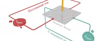
The Hall effect refers to a situation in which the Lorentz force acts on electrons moving in a conductor such that a potential difference - or in other words, voltage - occurs between the two sides of the conductor.
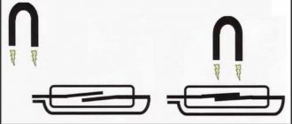
It should be noted that the arrows in the second figure show the directions of normal current flow, which means that the electrons are moving in the opposite direction. The direction of the Lorentz force is determined by the right-hand rule, which takes into account the direction of motion of the electron relative to the magnetic field. In the first picture, the electron is moving to the right, and the Lorentz force is directed upward. In the second picture, the electrons are moving to the left and the Lorentz force is downward, and thus negative charge accumulates on the bottom side of the conductor. The result is a potential difference that occurs between the top and bottom edges of the conductor, with the top edge being more positive than the bottom. This potential difference is called the Hall voltage:
\[U_{Hall}=-\frac{IB}{eρt}\]
This formula, which is applied to a conductive plate, tells us that the Hall voltage depends on the magnitude of the current (I) flowing through the conductor, on the magnetic induction (B), on the elementary charge of the electron (e), on the number of electrons per unit volume (ρ) and on the thickness of the plate (t).
Kinds
Digital Hall sensors are divided into unipolar and bipolar
In addition to the Hall effect, the laws of which are described by classical physics and are observed in all normal or close to normal experiments, there are several more varieties of the phenomenon of the appearance of a potential difference in a conductor.
Abnormal
Anomalous is any case of accumulation of charge on the edge of a conductor, in which the influence of external magnetic fields is excluded. A necessary condition is the perpendicular direction of the potential difference relative to the direction of the current.
The reasons why the anomalous Hall effect occurs usually lie in the magnetization of the conductor metal or the features of its molecular structure.
Quantum
The laws of the emergence of potential differences in the “quantum world” are studied using the example of a flat conductor of the DEG type (two-dimensional electron gas). Quantum is observed in strong magnetic fields and at low temperatures. It is expressed in the quantization of the Hall resistance, which has clearly defined “plateau areas” on the graph. The higher the resistance, the longer the plateau sections and the greater the difference between them.
The discovery of this phenomenon is one of the main milestones of modern quantum physics. Klaus von Klitzing, the discoverer of the quantum Hall effect, was awarded the Nobel Prize in 1985.
Fractional
Many advanced scientists in the 80s of the last century became interested in von Klitzing's research and continued to study the properties of the potential difference in the 2DEG. The greatest successes were achieved by Daniel Tsui and Horst Störmer, who analyzed the intermediate areas between the “resistance plateaus” and came to the conclusion that with a significant increase in the intensity of the magnetic fields, “plateau areas” can also be obtained at fractional values of the Landau electronic levels, for example, at n = 1 /3; n=2/5; n=3/7, etc.
This phenomenon was called the fractional quantum Hall effect, and its discoverers received the Nobel Prize in Physics in 1998. Currently, extensive research is underway on the quantum and fractional quantum types of this effect.
Spin
In 2003–2004, the behavior of electrons with antiparallel spins in conductors isolated from any magnetic fields was studied. The theoretical basis of the study was the theories of Vladimir Perel, put forward back in 1971. They were proven in practice, when it was possible to record the deviations of these groups of electrons to the opposite faces of the conductor. The movement of charged particles resembles the first type of effect - anomalous.
Using the Hall effect
The voltages generated by the Hall effect are small relative to the effects of noise, offset and temperature that typically affect the circuit, and thus true Hall effect sensors were not widespread until the advent of semiconductor technology enabled the creation of components with a high degree of integration, which included both the Hall element and the additional circuitry necessary to amplify the Hall voltage. However, Hall effect sensors are limited in their ability to measure small currents. For example, the sensitivity of the ACS712 from Allegro MicroSystems is 185 mV/A. This means that a current of 10 mA will produce an output voltage of only 1.85 mV. This voltage may be acceptable if the circuit is low noise, but if a 2 ohm resistor is included in the current path, the result may be 20 mV, which is much better.
The Hall effect is used in various sensors; devices based on the relatively simple relationship between current, magnetic field and voltage can be used to measure the position, speed and strength of a magnetic field. In this article, we will focus on devices that measure current through the Hall voltage generated when the magnetic field created by the current being measured is concentrated in the Hall sensor element.
Application of Hall sensors
- Hall sensors are widely used in household appliances. An eloquent example is washing machines. Users are puzzled by how laundry is weighed in advanced models. There are patents on the Internet where, with the help of springs or strain gauges, it is proposed to solve the problem head-on. Such devices are not capable of greater reliability, risking constant deformation. In addition, a couple of bricks are hung on the tank, which means that the total weight of the structure is large, which imposes restrictions. In practice, in washing machines, clothes are first abundantly moistened, then the total mass is estimated based on the acceleration speed of the drum. This is how the laundry is weighed, which subsequently determines the operating program of the equipment, the consumption of powder, water, and rinse aid.
- Hall sensors entered mass production for the first time in computer keyboards. Usually there is a sensitive element on the substrate, and a magnet is attached to the key. It is clear that there are no longer springs inside a modern keyboard, and the elastic force is created by polymers with a long service life. The solution is extremely successful: it is not the sensor or the elastic mechanical part that breaks, but the controller that fails.
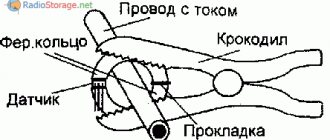
- The Hall sensor can be used to measure current strength (as in current clamps). The device can respond to changes in the electromagnetic field surrounding the wires. A so-called excitation winding (inductance made of copper wire) is created. The measured current is supplied to the taps, resulting in the formation of an electromagnetic wave, part of which is evaluated by a Hall sensor. The response depends directly on the measured value. The calculation is carried out according to formulas embedded, for example, in the controller. For accuracy, the device is calibrated by the manufacturer. Moreover, the advantages mentioned above remain, first of all, the absence of moving parts. Similarly, using Hall sensors, power measurement becomes possible.
Sensor Application - Converting DC voltage to AC voltage is considered an example of creating a generator. If the Hall sensor is in an alternating magnetic field, the output voltage follows the same shape. The efficiency of the device is not high. But the design is simplified to the maximum, and it becomes possible to directly transfer the shape of the magnetic field to the electric current.
- In connection with the facts described above, we note that Hall sensors allow you to control the consumption and charge level of batteries (by measuring the flowing current and integrating it over time). This makes it possible for them to be widely used. For example, in cell phones (up to 37% of the market). But experts believe that the most promising area is the electric vehicle segment, where the issue of energy availability will be vital.
- Thanks to the presence of the Earth's magnetic field, it becomes possible to create compasses based on Hall sensors. The only problem is that the value in T is uneven across the surface of continents and continents; measurement correction methods must be introduced. Due to this effect, automatic image stabilization systems for video cameras of mobile devices sometimes work.
- It is little known, but 52% of the profitability of Hall sensors comes from the automotive industry. This industry requires measuring wheel, crankshaft and camshaft speeds. Readers have already guessed that the Hall sensor will help with determining the position of the throttle valve and steering wheel. The automotive market has become the main driving force for further improvement of devices. Some systems are considered a de facto standard (ASIC, ASSP, ESC/ESP, etc.) on the market, and Hall sensors take an active part in them.
We recommend reading: ATS: design and principle of operation of the transfer system, use of automatic power switching
Advantages and disadvantages
The characteristics of different Hall effect current sensors vary greatly, so it is difficult to summarize the advantages and disadvantages of using the Hall effect relative to another common method of measuring current; namely, inserting a precision resistor into the current flow circuit and measuring the voltage drop that appears across it using a differential amplifier. In general, Hall effect sensors are valued for their "non-interference" properties and for providing electrical isolation between the current flow path and the sensing circuit. These devices are considered to have no effect because no significant resistance is inserted into the current path, and thus the circuit behaves as if there were no sensor at all when making measurements. An additional benefit is that the sensor dissipates minimal power; this is especially important when measuring large currents.
In terms of accuracy, currently available Hall sensors can achieve a minimum error of 1%. A well designed resistor based sensor can give better results, but one percent is usually sufficient for high current/voltage applications where Hall sensors are suitable.
Disadvantages of Hall sensors include limited frequency range and high cost. The ACS712 operates up to 80 kHz, and the Melexis MLX91208 range, which is positioned as “wideband,” is limited to the upper limit of 250 kHz. A resistive current sensor with a high-speed amplifier, on the other hand, can work well in the megahertz range. Additionally, as discussed above, the Hall effect is inherently limited when it comes to measuring small currents.
How to check the Hall sensor
It is recommended to carry out the test using a simple device that every driver can do with his own hands. He will need a resistance of 1 kOhm and a simple LED. A resistance is soldered to its leg, two pieces of any length of flexible wire convenient for operation are soldered to it, and the device is ready. Checking the Hall sensor is preceded by determining the presence of power supply to it:
- the distributor cap is removed;
- the plug box from the distributor is disconnected;
- the tester is connected to terminals 1 and 3, then the ignition is turned on.
If the car's electrical wiring is functioning normally, the tester will show a voltage of 10 volts or higher. After this, we connect the designed device to the same terminals - the LED lights up if the polarity has been chosen correctly. Otherwise, you need to swap the ends of the wires. The subsequent verification scheme is as follows:
- We do not touch the wire connected to the 1st terminal, but we transfer the end from the 3rd to the free 2nd terminal;
- rotate (manually or with a starter) the camshaft.
If you notice that the LED blinks during this process, then the ignition sensor does not need to be replaced. It is also possible to check the Hall sensor with a multimeter. It is connected to the ignition output contact, setting the device to voltmeter mode. The device arrow should move in the range of 0.4-3 Volts (an indicator of the health of the sensor).
How to check the Hall sensor
Malfunctions of the Hall sensor manifest themselves in different ways; even experienced specialists are not able to accurately determine the failure. There are a number of symptoms, but they indicate problems with the sensor indirectly, because These signs happen for different reasons:
- the engine does not start;
- at idle speed fluctuates;
- while driving, when the speed increases, the car jerks;
- The engine stalls for no reason.
If such symptoms occur, it is necessary to also check the Hall sensor. In addition to the method indicated in the article, there are several more. For example, the simplest thing is to ask someone for a working sensor and simply replace it on your car; if the problems go away on their own, then the sensor is faulty.
If you have a multimeter at hand, checking is easier than ever. To do this, you need to set the voltage measurement game mode on the device and test the indicators at the output of the sensor; if it is working properly, the voltage will vary from 0.4 to 11 V. Another common method involves checking in the absence of sparking (if there is power in the ignition system) and consists of in sensor simulation. The block is removed from the distributor and the ignition is turned on. Next, using a piece of wire, contacts 3 and 2 on the block are closed; if a spark appears on the central channel of the ignition coil, it means that the Hall sensor is faulty and requires replacement.
Another way is to check the existence of resistance on the sensor. To do this, you need to build a simple device, which consists of a 1 Kom resistor, a light diode, and flexible wiring. Solder a resistance to the leg of the light diode, and to it two wires of such length that it is convenient for operation (not short). Then remove the distributor cap, disconnect the distributor and the plug box. Then we check whether the electrical circuit is working properly. Therefore, we connect the electronics multimeter to the first and third terminals, then turn on the car’s ignition.
Under good conditions, the measurement on the device’s screen should be within 10-12 V. Then also connect the made mechanism to the same terminals. If you did everything correctly, the light diode will light up. Otherwise, you need to change the wiring places. Next you need to do this: do not touch the wire that is connected to the first terminal, do not touch the tip from the third terminal, transfer it to the free second terminal, turn the camshaft (by hand or with a starter). If the diode blinks when turning the shaft, this indicates that the sensor should not be changed.
Replacing the Hall sensor.
Voltmeter and multimeter
Using a voltmeter or a classic tester, you can easily check the condition of the device.
I think every motorist can use the tester. The task is to measure the voltage at the sensor output.
If the DC is in good condition, the tester will produce values in the range of 0.4-11 V.
A universal multimeter is used in exactly the same way. You just need to select the voltmeter mode on it.
Without testers
When testers are not available, testing can be done using a slightly different method.
Here you need to carry out step-by-step manipulations:
- the spark plug is connected to the wire terminal from the coil;
- the threaded part of the spark plug is connected to the ground;
- the carriage with the sensor is dismantled;
- connector is connected;
- the ignition is turned on;
- a metal object is held near the sensor;
- When a spark appears on the spark plug, the DH is operational.
Just be extremely careful when doing such manipulations with your own hands.
Sensor simulation
Quite an interesting and effective method. But here you will have to do a little work with your own hands.
We recommend reading: What are instrumentation and instrumentation systems: definition of the abbreviation, purpose
The principle of imitation is as follows. First, remove the block from the DH, which has 3 plugs. Next, start the ignition on the car, then connect outputs 3 and 6 to each other.
If a spark appears during such manipulation, then most likely the DC has failed.
Wedge with wedge
The simplest and most effective method that does not require you to equip yourself with a tester or multimeter. But you will need a known-good similar Hall sensor.
The essence of diagnosis is outrageously simple. You remove the old controller and install a new one in its place. If after the manipulation the symptoms go away and engine operation returns to normal, then simply leave the new part in place. If you borrowed a DH from a friend or neighbor in the garage, remove the device, say thank you, and go to the auto parts store.
Homemade tester
You can assemble an analogue of the tester from practically available materials.
The testing device consists of a regular LED, a 1 ohm resistance and two pieces of flexible wiring that need to be soldered to the leg.
Insulation
One of the main advantages of Hall sensors is electrical isolation, which in the context of circuit and system design is called galvanic isolation. The principle of galvanic isolation is used whenever a design requires two circuits to be coupled in a manner that prevents any possibility of electrical current flowing between them. A simple example is where a digital signal is transmitted through an opto-isolator, which converts voltage pulses into light pulses and thus transmits data optically rather than electrically. One of the main reasons for implementing galvanic isolation is to prevent problems associated with ground loops:
Basic circuit design principles assume that interconnected components share a common ground point, which is assumed to be 0 V. In real life, however, ground consists of conductors that have non-zero resistance, and these conductors serve as the return path for current to flow from the circuit back to the power source. Ohm's Law reminds us that current and resistance will produce voltage, and this voltage drop in the return path means that the ground in one part of the circuit is not exactly the same potential as the ground in another part of the circuit. This difference in ground potential can cause problems ranging from minor to catastrophic.
To prevent DC current from flowing between the two circuits, galvanic isolation is used, allowing the circuits to successfully communicate with different ground potentials. This is especially true for current measurements: a low-voltage sensor and processing circuit may be needed to monitor large, highly variable currents, such as in a motor drive circuit. These large, rapidly changing currents will cause significant voltage fluctuations in the return path circuit. The Hall effect sensor allows the system to monitor the drive current and protect the high-precision sensor circuitry from these harmful ground vibrations.
Features and Benefits
- Possibility of measurements in constant and alternating signal modes. The use of AC current and phase-sensitive detection eliminates thermal effects and errors associated with changes in system parameters over time, and significantly improves the signal-to-noise ratio. Constant signal mode is used when carrier trapping, rectification on non-ohmic contacts, or stray capacitances affect the alternating current.
- Possibility of measuring in various ways: Van der Pauw, etc. according to ASTM F-76 standard.
- A simple and convenient probe system that increases productivity.
- Compact tabletop design of the device.
- Wide current range and automatic setting of its value to minimize sample heating.
- Limiting the magnitude of the electric field to avoid impact ionization effects at low temperatures.
- Additional buffer amplifier/current source to expand the range of measured surface resistance to 100 GOhm/cm2.
- Software control of all measurement parameters, the ability to save and archive data, text and graphic printing.
- Additional measurement options at different temperatures:
- two fixed temperatures: room and 77K;
- cryostat with liquid nitrogen, from 90K to 500K;
- cryostat with continuous pumping of liquid helium, from 4K to 500K;
- cryostat with continuous pumping of liquid helium, from 4K to 300K.
- Rare earth permanent magnet providing high stability.
- During the measurement process, the plate is placed under an opaque casing, thereby eliminating errors caused by extraneous illumination.
- The probe design used allows for rapid installation and measurement at room temperature and liquid nitrogen temperature (77K) of plates up to 3 inches in diameter.
- Thorough verification of measurement accuracy, including contact quality control algorithms
- Electric contact burning system
Common Mode Voltage
Another important application of Hall sensors is to measure currents when operating at high voltages. In a resistive current sensor circuit, a differential amplifier measures the difference between the voltages on one side of the resistor and the other. The problem occurs when these voltages are large compared to ground potential:
Real amplifiers have a limited "common mode range", which means the device will not function properly, the difference between the input voltages is small, and the difference between them and ground is very large. The common-mode input voltage ranges of current-sensing amplifiers are typically within 80 or 100 V. Hall sensors, on the other hand, can convert current to voltage without reference to ground potential in the circuit being measured. Therefore, as long as the voltage is not high enough to cause physical damage, common mode voltage does not affect the operation of the Hall effect sensor.
Original article
- Robert Keim. Understanding and Applying the Hall Effect
Why does the Hall sensor fail?
Damage to the sensor can manifest itself with different symptoms - even a professional can sometimes find it difficult to determine the exact cause. Here are the signs that indicate a sensor failure:
- the engine does not start well;
- idling with constant interruptions;
- at high speeds the car jerks;
- the spark on the candles disappears;
- the engine suddenly stalls.
The main reason for the failure of this part is trivial - dirt has accumulated. As soon as this happens, the DH signals immediately. “Miracles” begin to happen to the car. However, it is wrong to blame this device for all the troubles - a thorough check is needed.
The disappearance of the spark is the main symptom of a faulty DC.
A common cause of failure is a lack of contact in the wiring. In total, the device has 3 contacts - connecting it to ground, to plus, to the switch. One of the contacts could have oxidized, causing the electrical circuit to break.
Finally, the wire may simply break or break. This occurs due to the fact that the vacuum ignition corrector displaces the platform on which the DC is located, shifting the ignition angle. To avoid such a misfortune, the wiring must be secured so that it bends in a loop.
If the high-voltage wiring in the car is worn out and lies next to the sensor wires, a high-voltage breakdown is possible. Often breakdowns occur in wet weather, when the wheel drives into a deep puddle.
The sensor wires should be kept away from the rest of the wiring. And the wiring needs to be changed as often as possible - at least once every 2 years.
A breakdown may occur due to overcharging of the battery generator - when the DC experienced too much load and one of the parts burned out at the input of the switch.
Signs of sensor malfunction
Hall sensor Malfunctions in the Hall sensor manifest themselves in different ways. Even an experienced technician will not always immediately identify the cause of engine problems. Here are some of the most common symptoms:
- The engine starts poorly or does not start at all.
- At idle, the engine runs rough and jerky.
- The car may jerk when driving at high speeds.
- The power unit stalls while driving.
If one of these signs appears, you must first check the serviceability of the Hall sensor. Also, do not exclude other malfunctions of the ignition system found in cars.
Signs of sensor malfunction.
Publications: Other (categorizer)
| Tweet |
Is it easy for a steel rod to break or tear? If you take a calculator and calculate the theoretical tensile strength of a material, taking into account the energy of its chemical bonds, you will get values that far exceed the actual strength of the products. So what actually happens when a load is applied, and why are experimental and theoretically calculated strength values so different? It turns out that under mechanical stress, materials behave according to the saying “where it is thin, it breaks,” and in this case, the “thin link” turns out to be the places where defects are localized, i.e. those areas where the continuous structure of the material is disrupted. Compare, for example, the effort required to break a bar of regular or aerated chocolate, a freshly cut or dry stick, or a baked or wet brick. It is thanks to defects that we can break glass along a line drawn by a glass cutter, or open a bag of juice or milk along pre-applied perforations.
What happens to the material during the transition from the bulk state to the nanostructured state? What happens if you gradually reduce the thickness of the rod, will it become even more fragile? This is exactly the question that A.A., an employee of the Farnborough Aviation Research Center, asked himself in 1920. Griffiths found the answer by conducting experiments with glass rods. He discovered a pattern that was not obvious at first glance: as the diameter of the rod decreased, its specific mechanical strength increased, and significantly. This change in strength depending on the diameter of the rod is due to the fact that as the thickness decreases, structural defects come to the surface more and more easily, leading to the formation of an almost ideal lattice. More and more, the strength of the material is approaching the theoretical one. The record holders among macroscopic objects are whisker crystals; their strength is tens of times greater than the strength and flexibility of the bulk material. Have you ever tried to bend or flatten your grandmother's diamond? And don’t try, at best you’ll end up with diamond powder! But diamond “mustaches” grown in special conditions can practically be tied into a knot. Moreover, in both cases we are talking about the same structural state of carbon - diamond. It turns out that “mustaches”, and not large diamonds, are the most perfect of crystals!
Most nanostructures are also virtually free of defects, and individual carbon nanotubes have tensile strengths exceeding 50 GPa. Nanotubes are difficult to break either by stretching or bending - despite their record strength, they are not a brittle material, and can be bent more than 90˚ without breaking. Similarly, it was discovered that the strength of layered structures depends on the thickness of the individual layers, and the strength of some bulk materials depends on the size of the grains that form them. These patterns are expressed by the Hall-Petch law, according to which the strength of a material increases as the particle size decreases according to the formula given on the left.
However, one should not think that an unlimited reduction in the thickness of the rod or the grain size of the material will lead to a natural improvement in its mechanical properties and the achievement of theoretical strength values. In fact, almost any material consists of grains, the boundaries of which are themselves defects along which rupture can occur. In some cases (but not always), a fairly simple pattern applies: the smaller the grain size, the less frictional force between them, and the easier it is to deform the material. In particular, at certain grain sizes (<50 nm), ceramics can transition from a strong state to a superplastic state, when even with low heating and low loads the material can be deformed (pressed or pulled) without destruction. This transition is explained by a change in the deformation mechanism - the grains no longer deform under load, but they begin to slide along the grain boundaries (grain boundary sliding). Of course, this expands technological capabilities. Thus, it is possible to obtain ceramics with nano-sized grains, by pressing or molding to set the shape of the part (ordinary ceramics can be strong, but brittle and will collapse even with small deformations), and then by annealing increase the grain size, giving the material good strength characteristics.
The practical use of the unique mechanical properties of nanomaterials is often limited by their high cost. However, it is not at all necessary to make the entire part from nanoparticles; it is enough to reinforce the easy-to-use material with strong nanofibers and nanotubes, just as the strength characteristics of concrete are increased by using steel rods - reinforcement. Today, the first products of the nanotechnology era have already appeared on sale: Easton Sports and Babolat have released baseball bats and tennis rackets reinforced with carbon nanotubes.
Literature:
Ch.P. Poole, F. J. Owens, Introduction to nanotechnology, John Wiley & Sons, 2003