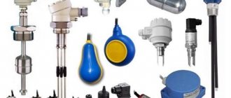
Ultrasonic sensors are widely used in a variety of areas of production, and in some way they are a universal means of solving many problems of process automation. Such sensors are used to determine the distance and location of various objects. Determining the level of liquid (for example, fuel consumption in transport), detecting labels, including transparent ones, monitoring the movement of an object, measuring distance - these are just some of the possible applications of ultrasonic sensors.
As a rule, there are many sources of pollution in production facilities, which can become a problem for many mechanisms, but the ultrasonic sensor, due to the nature of its operation, is absolutely not afraid of contamination, since the sensor housing, if necessary, can be reliably protected from possible mechanical influences.
Ultrasonic sensors are quite compact, have a high-quality design, and do not have various moving parts. In addition, the equipment requires virtually no maintenance.
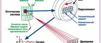
The ultrasonic sensor contains in its design a piezoelectric transducer, which is both an emitter and a receiver. The piezoelectric transducer emits a packet of sound pulses, then receives the echo, and converts the signal into voltage, which is supplied to the controller. Read more about the use of the piezoelectric effect in technology here.
The ultrasonic frequency ranges from 65 kHz to 400 kHz, depending on the type of transducer, and the pulse repetition rate ranges between 14 Hz and 140 Hz. The controller processes the data and calculates the distance to the object.
The active range of an ultrasonic sensor is the operating detection range. The detection range is the distance within which an ultrasonic transducer can detect an object, whether the object is approaching the sensing element axially or moving across the sound cone.
Operating principle
An ultrasonic rangefinder determines the distance to objects in the same way that dolphins or bats do. It generates sound pulses at 40 kHz and listens for echoes. Based on the time it takes for the sound wave to travel back and forth, you can unambiguously determine the distance to the object.
Unlike infrared rangefinders, ultrasonic rangefinder readings are not affected by light from the sun or the color of the object. But it may be difficult to judge the distance to furry or very thin objects. Therefore, it will be difficult to perform a high-tech mousetrap on it.
When sound is reflected from an obstacle, we hear an echo. The bat uses the reflection of ultrasonic waves to fly in the dark and to hunt insects. An echo sounder works on the same principle, which is used to measure the depth of water under the bottom of a ship or search for fish.
The principle of transmitting and receiving ultrasonic energy is the basis of many very popular ultrasonic speed sensors and detectors. Ultrasonic waves are mechanical acoustic waves whose frequency lies beyond the audibility of the human ear - more than 20 kHz. However, signals of these frequencies are perceived by some animals: dogs, cats, rodents and insects. And some species of mammals, such as bats and dolphins, communicate with each other using ultrasonic signals.
ULTRASONIC SENSOR Lego Mindstorm EV 3. SEE THE ROOT
Technical Specifications and Product Features:
- Distance measurement ranging from 1 to 250 cm
- Measurement accuracy up to +/- 1 cm
- The front illumination in the form of a red ring is constantly on when transmitting a signal and blinks when listening to the broadcast.
- If the ultrasonic signal is recognized, the sensor returns a logical value "True"
- Automatic identification is carried out by EV3 microcomputer software
Rice. 1 Ultrasonic sensor Lego Mindstorm EV 3 (cost including internal microcontroller and signal amplification chips $50, cost price $5)
Rice. 2 Lego Mindstorm EV 3 ultrasonic sensor circuit (ultrasonic sensor hardware schematics) is built on an STM8S103F3 microcontroller
- Introduction to stm8
- Microcontroller STM8S103F3
- LEGO MINDSTORMS EV3 central microcontroller circuit diagram programmable brick main hardware schematics
Rice. 3 Ultrasonic emitter AW8T40 and receiver AW8R40 ultrasonic sensor Lego Mindstorm EV 3
Tasks
Now that we can calculate distance using a rangefinder, we will make several useful devices.
- Construction rangefinder. The program measures the distance every 100ms using a rangefinder and displays the result on a symbolic LCD display. For convenience, the resulting device can be placed in a small case and powered by batteries.
- Ultrasonic cane. Let's write a program that will “beep” a buzzer at different frequencies, depending on the measured distance. For example, if the distance to an obstacle is more than three meters, the buzzer makes a sound once every half a second. At a distance of 1 meter - once every 100ms. Less than 10cm - beeps constantly.
Ultrasonic sensor HC-SR04
Ultrasonic Sensor HC-SR04 – Ultrasonic Ranging Module HC – SR04 – Ultrasonic Sensor Distance Measuring Module – Sonar
Ultrasonic rangefinder HC SR04 is the most famous sensor for use in Arduino, Raspberry
Pi, ESP8266 and ESP32 modules.
Allows you to measure the distance to an object in the range from 2 to 400 (180) cm. For example, if you want to build a robot that avoids obstacles, then this rangefinder is perfect for your tasks.
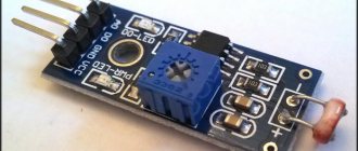
The sensor has small dimensions and a simple interface. Rice. 4 Appearance of the ultrasonic sensor (sonar, ultrasonic sensor, ultrasonic module) HC-SR04
Applications and Benefits
Distance sensors are widely used in everyday life. Cars are equipped with parking sensors. In addition to measuring distances, they can simply register the presence of an object within the measuring range, for example in hazardous areas of working machines. Such devices are used in a wide range of industries, for example:
- in the press;
- when converting;
- in robotics;
- during materials processing;
- in transportation, etc.
Distance sensors can be used to monitor or indicate the position of objects and materials. These instruments are so widely used that they can be reliably implemented in applications such as measuring material grain size, determining water levels and much more, since ultrasound reflects from almost any surface. The only exceptions are soft materials, such as wool. Its surface absorbs ultrasonic waves and does not reflect sound.
Ultrasonic distance meters are superior to infrared sensors because they are unaffected by smoke and other elements. Although this system is not completely perfect, it is a good, reliable and cost-effective solution for determining distance and obstacles.
Gadgets connect to all common types of automation and telemetry tools. Applications range from simple analog connections to complex data networks with multiple sensors.
Names of terminals and ultrasonic emitters of the module
- Vcc is the positive power contact.
- Trig - digital input. To start the measurement, it is necessary to apply a pulse (logical unit) with a duration of 10 μs to this input. It is recommended to send the next pulse no earlier than 50 ms. which is related to the processing time of the first pulse.
- Echo - digital output. After processing the reflected signal, a pulse (logical unit) will be sent to this output, with a duration proportional to the distance to the object.
- GND - negative power contact (ground).
- The left ultrasonic emitter (marked with the letter T - transmiter) is an ultrasonic signal transmitter, the right ultrasonic emitter (marked with the letter R - receiver) is a receiver of the ultrasonic signal (echo) reflected from the object.
Ultrasonic range finder
Using piezoelectric or magnetostrictive transducers, we can create a device that measures the distance to objects - an ultrasonic rangefinder, which works as follows.
At the moment of measurement, we create an electrical vibration using a generator, which, transformed (for example, using a piezocrystal) into an ultrasonic wave, is emitted into the surrounding space. This wave is reflected from the obstacle and returns as an echo to the receiver (a piezo crystal can also be used). Measuring the time between sending and receiving our reflected signal
*** QuickLaTeX cannot compile formula: \Delta t *** Error message: Cannot connect to QuickLaTeX server: SSL certificate problem: certificate has expired Please make sure your server/PHP settings allow HTTP requests to external resources (“allow_url_fopen”, etc .) These links might help in finding a solution: https://wordpress.org/extend/plugins/core-control/ https://wordpress.org/support/topic/an-unexpected-http-error-occurred-during- the-api-request-on-wordpress-3?replies=37 and, knowing the speed of the sound wave *** QuickLaTeX cannot compile formula: v *** Error message: Cannot connect to QuickLaTeX server: SSL certificate problem: certificate has expired Please make sure your server/PHP settings allow HTTP requests to external resources (“allow_url_fopen”, etc.) These links might help in finding a solution: https://wordpress.org/extend/plugins/core-control/ https://wordpress .org/support/topic/an-unexpected-http-error-occurred-during-the-api-request-on-wordpress-3?replies=37 distributed in this environment (for air this value is about 340 m/s) , we can calculate the distance *** QuickLaTeX cannot compile formula: d *** Error message: Cannot connect to QuickLaTeX server: SSL certificate problem: certificate has expired Please make sure your server/PHP settings allow HTTP requests to external resources (“allow_url_fopen” ", etc.) These links might help in finding a solution: https://wordpress.org/extend/plugins/core-control/ https://wordpress.org/support/topic/an-unexpected-http-error-occurred -during-the-api-request-on-wordpress-3?replies=37
to the obstacle.
*** QuickLaTeX cannot compile formula: \[d=\frac{v\Delta t}{2}\] *** Error message: Cannot connect to QuickLaTeX server: SSL certificate problem: certificate has expired Please make sure your server/ PHP settings allow HTTP requests to external resources (“allow_url_fopen”, etc.) These links might help in finding a solution: https://wordpress.org/extend/plugins/core-control/ https://wordpress.org/support/ topic/an-unexpected-http-error-occurred-during-the-api-request-on-wordpress-3?replies=37
Operating principle of ultrasonic rangefinder
Characteristics
- Supply voltage: 5V. Model HC-SR04 + operates in the range of 3.3V-5V (marked as HC-SR04 + on the back of the module board)
- Quiet mode consumption: 2 mA
- Operating consumption: 15 mA
- Maximum sensor polling rate: 20 Hz (50 ms polling period)
- Ultrasound frequency: 40KHz
- Viewing range: 2 cm - 4 m (1.8 m)
- Resolution (output signal gradation): 0.3 cm
- Effective viewing angle: 15°
- Working viewing angle: 30°
- weight - 8.28 grams
- Dimensions: 45*20*15 mm. LxWxD (W - excluding connection contacts)
Rice. 5 Dimensions of ultrasonic sensor HC-SR04
- Attention: ! It is not recommended to connect the module directly to the microcontroller board connected to the power supply, it is necessary to turn off the power supply when connecting the module, the GND pin of the module should be connected first, otherwise it may affect the normal operation of the module.
- ! When testing the module for measurement range and accuracy, the size of the area of the scanned object must be at least 0.5 square meters and its surface must be as hard and smooth as possible, otherwise it will affect the measurement results.
Rice. 6 Directional pattern of the ultrasonic sensor HC-SR04. Taken from the documentation for this sensor
Description of work:
Sensor viewing angle test, taken from the description on the website:
- https://life-prog.ru/view_msinv.php?id=62%D0%BC%D0%BE%D0%B6%D0%B5%D1%82
An ultrasonic distance sensor determines the distance to an object by measuring the time a sound wave is reflected from the object. The frequency of the sound wave is within the frequency of ultrasound, which ensures a concentrated direction of the sound wave, since sound with a high frequency is less dissipated in the environment. A typical ultrasonic distance sensor consists of two membranes, one of which generates the sound and the other of which registers the displayed echo. Figuratively speaking, we are dealing with a speaker and a microphone. The sound generator creates a small ultrasonic pulse with a certain period and starts the timer. Figure 3 – Ultrasonic distance sensor HC-SR04 The second membrane registers the arrival of the displayed pulse and stops the timer. From the timer time and the speed of sound it is possible to calculate the distance traveled by the sound wave. The object's distance is approximately half the distance traveled by the sound wave. Figure 4 - Operating principle of an ultrasonic distance sensor Limitations associated with the use of an ultrasonic distance sensor: 1. Partial reflections, or as they are called spurious echoes, can distort the measurement results (the reason may be surfaces that are curved or inclined relative to the direction of emission of the signal) . 2. Measuring objects made of sound-absorbing, insulating materials or having a fabric (wool) surface may lead to incorrect measurements due to signal absorption (attenuation). 3. The smaller the object, the less reflective surface it has. This results in a weaker reflected signal. 4. In high humidity (rain, snow), the signal may also be partially reflected from drops (snowflakes), which leads to a spurious echo signal.
The operating principle of the sensor is as follows: one of the piezoelements emits an ultrasonic wave when a pulse lasting 15 microseconds is applied, and the other piezoelement receives the same reflected wave from an obstacle. Then the delay time from transmission to reception of the wave is measured, then the distance is calculated and a signal is transmitted to the leg of the Echo sensor, with a duration proportional to the distance to the obstacle. All we have to do is send an impulse to the sensor, receive it and calculate the distance. Today we will learn how to work with HC-SR04 on BASCOM-AVR.
Let's set ourselves a task: to assemble a device that should measure the distance to any object using the HC-SR04 sensor and transmit data via UART to a PC.
For this purpose, you can use almost any AVR microcontroller, since the algorithm is very simple. I took Atmega8, and the result was the following circuit diagram of the device:
The description of the operating principle of the ultrasonic range finder HC - SR 04 can be divided into the following steps:
The next pulse can be emitted only after the echo from the previous one has disappeared. This time is called the cycle period. The recommended period between pulses should be at least 50 ms.
If a pulse with a duration of 10 μs is applied to the signal pin (Trig), the ultrasonic module will emit eight bursts of ultrasonic signal with a frequency of 40 kHz and detect their echo. The measured distance to the object is proportional to the width of the echo (Echo) and can be calculated using the formula shown in the graph above.
The sensor sends ultrasonic pulses and listens for echoes. We apply a high-level pulse with a duration of 10–15 microseconds to the Trig input of the sensor. The sensor sends out an ultrasonic "chirp" signal of eight short pulses at a frequency above the limit of human hearing range. The sensor electronics know the speed of sound in air. By measuring the time between sent and received ultrasound, the HC-SR04 ultrasonic sensor generates an output signal. This principle of echolocation is used by dolphins and bats. After about a microsecond, the HC-SR04 ultrasonic sensor outputs a high-level pulse at the Echo output for up to 38 milliseconds. If no obstacles are detected, the output will be a signal with a duration of 38 ms. Thus, to operate the sensor, the device electronics require one digital control output and one input for the sensor signal. The pulse length at the Echo output is proportional to the distance to the obstacle. The distance is calculated by the formula: S=F/58, where S is the distance in centimeters, F is the pulse duration in microseconds. There is an Ultrasonic software library for interaction between Arduino and the sensor.
Step 1: A pulse lasting 10 microseconds is applied Trig input For the rangefinder, this is a command to start measuring the distance in front of it.
Step 2: The device generates 8 ultrasonic pulses with a frequency of 40 kHz through the output sensor T.
Step 3: The sound wave is reflected from the obstacle and hits the receiving sensor R.
Step 4: Echo output , the duration of which is directly proportional to the measured distance.
Step 5: On the side of the control controller, we convert the duration of the Echo into distance using the formula: pulse width (μs) / 58 = distance (cm) .
The figure below shows timing diagrams that clearly explain the steps listed.
Short pulses with a duration of 10 μs must be applied to the Trig signal. This pulse triggers the echo locator. It already generates a packet of ultrasonic pulses (40 kHz) for the emitter and itself catches the reflected echo. Based on the time the sound travels back and forth, the sensor determines the distance. For us, the sensor itself gives an impulse to the Echo contact with a duration proportional to the distance. Echo signal duration is from 150µs to 25ms. If there is no answer, then the Echo duration is about 40ms. The distance to the object can be calculated by dividing the duration in microseconds of the echo by 58. The distance in centimeters is obtained. The maximum distance that can be measured according to the documentation is 5 meters. The recommended sensor polling period is 50-10ms. The sensor's radiation pattern is not very sharp - about thirty degrees.
- The operation of the ultrasonic rangefinder HC-SR04 is based on the principle of echolocation. It emits sound pulses into space and receives a signal reflected from an obstacle. The distance to the object is determined by the time of propagation of the sound wave to the obstacle and back. The sound wave is triggered by applying a positive pulse lasting at least 10 microseconds to the TRIG leg of the rangefinder. As soon as the pulse ends, the rangefinder emits a packet of sound pulses with a frequency of 40 kHz into the space in front of it. At the same time, the algorithm for determining the delay time of the reflected signal is launched, and a logical unit appears on the ECHO rangefinder leg. As soon as the sensor detects the reflected signal, a logical zero appears at the ECHO pin. The duration of this signal (“Echo Delay” in the figure) determines the distance to the object. The distance measurement range of the HC-SR04 rangefinder is up to 4 meters with a resolution of 0.3 cm. The viewing angle is 30 degrees, the effective angle is 15 degrees. Current consumption in standby mode is 2 mA, during operation - 15 mA.
- The sound wave is triggered by applying a positive pulse lasting at least 10 microseconds to the TRIG leg of the rangefinder. As soon as the pulse ends, the rangefinder emits a packet of sound pulses with a frequency of 40 kHz into the space in front of it. At the same time, the algorithm for determining the delay time of the reflected signal is launched, and a logical unit appears on the ECHO rangefinder leg. As soon as the sensor detects the reflected signal, a logical zero appears at the ECHO pin. The duration of this signal (“Echo Delay” in the figure) determines the distance to the object. The distance measurement range of the HC-SR04 rangefinder is up to 4 meters with a resolution of 0.3 cm. The viewing angle is 30 degrees, the effective angle is 15 degrees. Current consumption in standby mode is 2 mA, during operation - 15 mA.
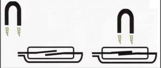
Rice. 40. Piezoelectric ultrasonic transducer: A - input voltage causes the element to bend, which causes the generation of ultrasonic waves. Conversely, as a result of the influence of waves, voltage appears at the output of the converter; B - ultrasonic transducer with an open aperture for working in air
- More details: https://www.kakprosto.ru/kak-918792-kak-podklyuchit-ultrazvukovoy-dalnomer-hc-sr04-k-arduino#ixzz4PeP45Mxx
- Contacts, in order from left to right, from the front side:
- Vcc – 5V power supply
- Echo - exit
- Gnd – ground
Trig – input
Work process:
- We connect the sensor to power and to the control device
- We send a signal with a duration of 10 μs to the rangefinder input (Trig) (or a little more, it triggers at 10 μs)
- The sensor speaker emits 8 signals at 40 kHz, and the microphone receives their echo (or does not receive it)
- The sensor sends a signal to its output (Echo) with a duration corresponding to the distance to the obstacle: 150 μs (at 2 cm to the obstacle) – 25 ms (at 4 m to the obstacle) and 38 ms in the absence of an obstacle. Note: sound travels a distance of 4 cm (2 cm from the speaker to the obstacle and 2 cm back to the microphone) in 0.04 m / 335 m/s = 0.000119 s = 119 μs and 8 m in 8 m / 335 m/s = 0.023881 s = 23.881 ms.
What time passes from the sensor being triggered by an input signal to the beginning of point 3 and from the beginning of point 3 to the beginning of point 4 is not stated anywhere - this will soon be found out by me experimentally.
To calculate the distance to an obstacle, the following formulas are used:
- Output pulse length in microseconds / 58 = distance in centimeters
- Output pulse length in microseconds / 148 = distance in inches
The HC-SR04 module circuit has 2 converters of ultrasonic signals into low-power electrical signals, one TCT40-16T - ( T - Transmiter in the diagram is designated as Emit MK2, see diagram) is designed for transmitting (emission) ultrasonic waves into the surrounding space and the second TCT40-16R ( R - Receive in the diagram is designated as Receive MK1, see diagram) for receiving reflected ultrasonic waves from objects in the surrounding world.
Relatively high voltage is required to transmit ultrasonic waves. MAX232 microcircuit (designation on the board is U3, see diagram) amplifies the 5 volt input supply voltage to +/- 9-10 volts. MAX232 microcircuit is connected between two outputs (T OUT1 - pin 14 and T OUT2 pin 7, see diagram), so that in fact the amplitude of the voltage value of the pulses supplied to the ultrasonic transmitter reaches up to 20 volts. MAX232 microcircuit through transistor Q2 (in the new circuit it is absent and power is supplied directly to input 16 of the microcircuit and in this case the microcontroller does not turn off) for some time before and during pulse emission, since internal charge switching creates excess noise on the receiving side module. When the module goes into receive mode on the MAX232 chip, power is turned off at output 10 - Signal of the EM78P153S microcontroller (EM78P153S Chinese microcontroller operates at a frequency < 27 MHz.
the TCT40-16R ultrasonic signal converter is carried out by the LM324 microcircuit (designation on the board - U1, see diagram), which contains 4 operational amplifiers. Operational amplifier U2D (see diagram) amplifies the signal 6 times. Operational amplifier U2C has feedback (1st order) and is a bandpass filter, then operational amplifier U2B amplifies the input signal 8 more times. The last operational amplifier U2A is used together with Q1 as a hysteresis comparator where the rectangular pulses and the analog input signal are separated. I simulated the filter in PSpice and it is not centered at 40KHz as it should be but instead it has a peak at 18kHz. By changing only two resistors (R13 to 2K2 and R11 to 18K), the filter response is shifted to the pulse frequency, and this significantly increases detection sensitivity.
MICROCONTROLLER ESP-8266 AND ULTRASONIC SENSOR HC-SR04
Redesign of ultrasonic sensor HC-SR04
Rice. 4 Ultrasonic emitter/receiver TCT40-16R/T (cost including internal microcontroller and signal amplification chips < $1)
Rice. 5 Spatial radiation diagram of the ultrasonic emitter/receiver TCT40-16R/T (if we saw ultrasound, then we would see the propagation of ultrasonic waves in space)
Characteristics of ultrasonic emitter/receiver TCT40-16R/T
1. Model: TCT40-16R/T (16mm in diameter) 2. Nominal frequency (KHz): 40KHz 3. Sound pressure emission At10v (dB=0.02mPa): ≥ 117dB 4. Receiver sensitivity at40KHz (dB=V/ ubar): ≥-65dB 5. Electrostatic potential at1KHz, <1V (PF): 2000±30%
Ultrasonic transducers reference 1
Ultrasonic transducers help 2
APPLICATION
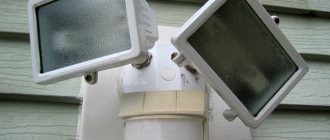
Echo sounder. Category “How does it work?”
Murata Ultrasonic Sensors
Sensors designed for parking machines have high sensitivity: with a resonant frequency of 40 kHz. The sensor range reaches 1.5 meters with a resolution of 9 mm. Sensors are available with different radiation patterns, both symmetrical (circular) and asymmetrical (oval).
Connecting to Arduino
If you plan to use the HC-SR04 ultrasonic rangefinder with Arduino you can use the existing libraries:
- Ultrasonic is the most popular library for the HC-SR04.
- NewPing is more accurate and faster.
- Ultrasonic rangefinder URM37
Pinout:
- Vcc - positive power supply
- TRIG - TRIG input
- ECHO - ECHO output
- GND - power zero
The power pins are supplied with a constant voltage of 5 V, the current consumption in operating mode is about 15 mA.
The TRIG input connects to any pin of the microcontroller. A pulse digital signal with a duration of 10 μs must be supplied to this pin. Based on the signal at the TRIG input, the sensor sends ultrasonic pulses.
After receiving the reflected signal, the sensor generates a pulse signal at the ECHO pin, the duration of which is proportional to the distance to the obstacle.
The sensor pins can be connected to a breadboard or Arduino female-male wires. And with Troyka Shield through female-to-female wires.
- Garage parking sensor
This rangefinder can serve as an excellent sensor for a robot, thanks to which it can determine distances to objects, avoid obstacles, or build a map of the room. It can also be used as a sensor for alarms that are triggered when objects approach.
Specifications
https://www.yourmestudio.com/rcw-0002-ultrasonic-ranging-module-p717.html
- Supply voltage: 5 V
- Quiet mode consumption: 2 mA
- Operating consumption: 15 mA
- Distance range: 2–400 cm
- Effective viewing angle: 15°
- Working viewing angle: 30°
Product Description:
TK T 40-16 t/r 1
- (Tc): piezoceramics Ultrasonic sensor
- (T): Category t-generality
- (40): Center frequency (kHz)
- (16): outer diameter? (mm)
- (T): use mode: emitter; r-receiver; TR-compatible emitter and receiver
- (1): ID - 1,2, 3...
Circuit testing
- 1 Sine Wave Generator 1 Swept Signal Generator
- 2 cymometer 2 Frequency meter
- 3 standard speakers 3 voltmeter
- 4 Get sensor model 4 emit sensor model
- 5 oscilloscope 5 Standard microphone
- 6 audio frequency characteristics Instrument display
Product performance 1). Rated Frequency (KHz): 40KHz 2). emit sound pressureat10V(=0.02Mpa):? 117dB 3). Reception Receiver sensitivity at40KHz (dB = v/ubar):?-65dB 4). Electrostatic potential at1KHz, <1V (PF): 2000 +/-30% 5). Detection range (m): 0.2~20 6).-6dB direction angle: 80o 7). Sheathing material: aluminum 8). Trim COLOR: silver
Useful resources:
Ultrasonic rangefinder HC-SR04 connection to Arduino
Ultrasonic sensor HC-SR04 – rangefinder on a microcontroller
https://www.elecfreaks.com/store/download/product/Sensor/HC-SR04/HC-SR04_Ultrasonic_Module_User_Guide.pdf
https://robocraft.ru/blog/arduino/770.html
Ultrasonic Distance Sensor HC-SR04
Pengetahuan Dasar Timer Untuk Pengukuran Jarak Dengan Ultrasonic
Triggering a Servo Using HC-SR04 Distance Sensor and Arduino
https://robocraft.ru/blog/electronics/772.html
Raspi-sump October 2014 Embedded Release LinuxJournal
https://www.arduino.cc/en/Tutorial/Ping
Simple ultrasonic range finder using HC-SR04
Obstacle Sensor using Arduino and HCSR04
How to Test DYP-ME007 Ultrasonic Rangefinder Using NE555 and Multimeter
https://macduino.blogspot.ru/2013/11/HC-SR04-part1.html
https://amperka.ru/product/ultrasonic-urm37
https://image.dfrobot.com/image/data/SEN0002/URM04V2.0Mannual1.1.pdf
https://people.ece.cornell.edu/land/courses/ece4760/FinalProjects/s2012/xz227_gm348/xz227_gm348/URM3.2_Mannual_Rev2.pdf
RCW-0012 Ultrasonic Module Distance Measuring Transducer Test Indication Module
https://www.farnell.com/datasheets/81163.pdf?_ga=1.169892256.1853603956.1478607467
https://chinaultrasound.en.alibaba.com/product/60268805778-800581237/40Khz_TCT40_16R_T_Air_Ultrasonic_Ceramic_Transducer_Ultrasonic_Sensor.html
Piezoelectric effect and magnetostriction
How to obtain vibrations in the ultrasonic range?
The crystals of some materials (such as quartz) are capable of very rapid vibrations when electricity passes through them. This is the so-called inverse piezoelectric effect. As they vibrate, they push and pull the air around them, thereby producing ultrasonic waves. Devices that produce ultrasonic waves using piezoelectricity are known as piezoelectric transducers. Piezoelectric crystals also work in the reverse order: if ultrasonic waves, propagating through the air, collide with a piezoelectric crystal, slightly deform its surface, resulting in an electric field in the crystal. So, if we connect a piezoelectric crystal to an electrical voltage meter, we get an ultrasound detector.
Piezoelectric effect
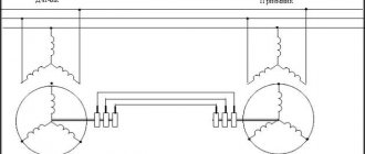
Ultrasonic waves can be produced using magnetism instead of electricity. Just as piezoelectric crystals produce ultrasonic waves in response to electricity, there are other crystals that emit ultrasound in response to magnetism. This is the magnetostriction effect. Such crystals are called magnetostrictive crystals. Sensors using them are called magnetostrictive transducers.
In English literature, ultrasonic sensors are called ultrasound sensor.