In accordance with the “Rules for the technical operation of consumer electrical installations,” a single-line power supply diagram is one of the types of executive documentation that must be available to organizations and individuals operating electrical networks and equipment without fail. In this article by the editors of HomeMyHome.ru we will talk in detail about what such a scheme is, what it should include, as well as the rules for its design in accordance with all regulatory documents.
Single-line diagram of power supply for a country house
Features of reading circuits
In circuit diagrams, conductors (or tracks) are indicated by lines.
This designates conductors that intersect, but they do not have a common connection and are not electrically connected to each other. And this is what they look like if there is a connection between them. The black dot is a node in the circuit. A node is a connection of several conductors or parts together. They are electrically connected to each other.
Common point
Beginner radio amateurs often have a question: what is this symbol on the diagram?
This is the common point (GND, ground). Previously, it was called the common wire. This is how a single power wire is designated. Usually this is a minus of nutrition. Previously, in the diagrams they could make the common wire and the power plus. In this case, the diagram without a common point would look like this:
A common point with unipolar power supply looks visually better and more compact than if you simply make a single line between them.
It is also called a common point because any other points on the diagrams can be measured relative to it. For example, place the multimeter probe on a common point, and with the second probe you can check any part of the circuit in the diagram.
Why can it be called ground (GND)? Previously, the chassis of the device body could be used as a common wire. This has caused confusion between grounding and earth. It is interpreted in the context of the schema. The circuit that was discussed above - the common point (ground) is simply a minus of the power supply. Another thing is bipolar current sources and grounding.
Bipolar power supply and common point
In a bipolar supply, the common point is the middle contact between plus and minus.
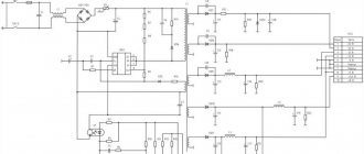
Grounding
An example of grounding would be a filter in computer power supplies.
From the capacitor filter, noise goes to the power supply housing. This is grounding. And from the power supply they must go into the outlet if you have a ground connection, otherwise the body of the power supply itself may be energized. The currents there are not large, they are not life-threatening. This is done to reduce impulse noise in the power supply and safety.
Sometimes in power supplies, instead of the housing, noise from the capacitor goes to a common point. It all depends on the design and circuitry. In this case, there will be more interference than with grounding.
In general, there are different grounding connections on the diagrams. For example, in digital technology, analog ground is separated from digital ground. so as not to disrupt the operating modes of the circuit. Pulse noise can affect the analog part of the circuit.
Types of electrical circuits
1.1. Structural scheme
This type of document is the simplest and gives an understanding of how the electrical installation works and what it consists of. A graphical representation of all circuit elements allows you to initially see the overall picture in order to move on to a more complex connection or repair process. The reading order is indicated by arrows and explanatory inscriptions, which allows even a novice electrician to understand the structural electrical diagram. You can see the principle of construction in the example below:
Figure 1 — Block diagram
1.2. Functional diagram
The functional electrical diagram of the installation, in fact, is not too different from the structural one. The only difference is a more detailed description of all the components of the chain. This document looks like this:
Figure 2 - Functional diagram
1.3. Schematic diagram
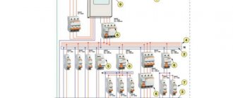
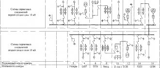
The electrical circuit diagram is most often used in distribution networks, because gives the most comprehensive explanation of how the electrical equipment in question works. Such a drawing must necessarily indicate all the functional components of the circuit and the type of connection between them. In turn, the circuit diagram can have two varieties: single-line (Figure 3) or complete (Figure 4). In the first case, only primary networks, also called power networks, are shown in the drawing. An example of a single line image can be seen below:
Figure 3 - Single line circuit diagram
A complete circuit diagram can be expanded or elemental. If the electrical installation is simple and all the explanations can be put on one main drawing, it is enough to make a detailed plan. If you are dealing with complex equipment that includes a control, automation and measurement circuit, it is better to separate all the individual components into different sheets so as not to get confused.
Figure 4 - Complete circuit diagram
There is also a schematic diagram of the product. This type of document is a kind of copy from the general plan, which only indicates how a certain unit works and what it consists of.
1.4. Wiring diagram
We most often use this type of electrical diagram when we talk about how to install electrical wiring yourself. The fact is that the wiring diagram can show the exact location of all the elements of the circuit, the method of connecting them, as well as the alphanumeric characteristics of the installations that make up the drawing. If we take Figure 5 as an example of the electrical wiring diagram in a one-room apartment, we will see where we need to place sockets, switches, lamps and other products.
Figure 5 - Wiring diagram
The main purpose of a wiring diagram is to provide a guide for electrical work. According to the prepared drawing, you can understand where, what and how to connect.
1.5. Combined scheme
Well, the last electrical circuit used in distribution networks is the combined Figure 6, which can include several types and types of documents. It is used if it is possible to indicate all the important features of the circuit without too much cluttering of the drawing. The integrated project is used most often in enterprises. Home craftsmen are unlikely to encounter this type of scheme. You can see an example below:
Figure 6 - Integrated scheme
Ratings of radio components
In general, there are disagreements in this regard. According to GOST at the moment, the nominal values of parts are not indicated on circuit diagrams. This is done in order not to clutter the diagram with information.
The circuit diagram is accompanied by a list of parts, wiring and structural diagrams, as well as a printed circuit board.
There is another generally accepted standard. The diagrams indicate the ratings of some parts and their operating voltages.
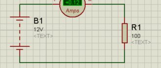
For example, in this circuit there are two resistors.
By default, resistance without a prefix is written only as a number. R2 has a resistance of 220 Ohms. And R3 has a letter after the number. The resistance of this resistor reads 2.2k ohms (2,200 ohms).
Consider two capacitors in the diagram.
In this case, C5 is a non-polar capacitor with a capacitance of 0.01 µF. Microfarads can be designated either uF or uF. And capacitor C6 is polar and electrolytic. This is indicated by the plus sign near the UGO. Capacitance C6 is 470 μF. The rated operating voltage is indicated in volts. Here for C6 it is 16 V.
Nanofarads are denoted as nF.
If there is no microfarad (uF) or nanofarad (nF) prefix on the circuit, then the capacitance of this capacitor is measured in picofarads (pF, pF). This condition is not common, so carefully study the diagram you are about to read or assemble. There are few capacitances in farads (F), so µF, nF and pF are used.
Single-line design diagram
Designing a design diagram is necessary when the object (be it a house, cottage or other premises) has not yet been in operation. Accordingly, this means that it does not have any electrical installation (there was no power supply at all).
In this case, the first stage in the design of a single-line design diagram is the need to carry out the entire complex of computational activities. And based on the data received, continue its preparation in terms of design work for the installation of the electrical network itself. All calculations are based on the expected loads that will occur during operation of the electrical network. Accordingly, the characteristics of the selection of all elements of the electrical network (conductors and their components), as well as automatic machines, are determined. Each of the above network components must withstand the loads designed for it.
When designing a single-line diagram, electrical energy is distributed from the switchboard through an electrical network, which is the same for all consumers of electrical energy. Since in the modern world many more high-power household electrical appliances are used compared to Soviet times, the need to install, in addition to circuit breakers, also a residual current device, which is also selected based on the above typical calculations, comes to the fore.
What is a datasheet and why is it needed?
Datasheet is a technical specification that provides complete information about a radio component. All technical information, basic connection diagram, parameters and types of housings are indicated in this document.
Datasheets come in different languages, mostly in English. There are also translated versions.
Documentation for the NE555 chip. The body and appearance of the part are drawn.
The microcircuit, its parameters and operating conditions are described in detail here.
Such documentation is available for any detail. This is very convenient and informative, especially when searching for analogues. And with the help of the Internet, searching for analogue parts or diagrams has become even easier.
The datasheet also allows you to identify an unknown part or microcircuit. Just write its name in a search engine, add the word datasheet, and all the documentation will be in the search results.
Power supply designation
Any radio-electronic device is capable of performing its functions only in the presence of electricity. There are fundamentally two types of electricity sources: direct and alternating current. This article deals exclusively with DC sources. These include batteries or galvanic cells, rechargeable batteries, various types of power supplies, etc.
There are thousands of thousands of different batteries, galvanic cells, etc. in the world, which differ in both appearance and design. However, they are all united by a common functional purpose - to supply electronic equipment with direct current. Therefore, in the drawings of electrical circuits, sources are designated uniformly, but still with some minor differences.
It is customary to draw electrical circuits from left to right, that is, the same way as writing text. However, this rule is not always followed, especially by radio amateurs. But, nevertheless, this rule should be adopted and applied in the future.
A galvanic cell or one battery, no matter “finger”, “pinky” or tablet type, is designated as follows: two parallel lines of different lengths. A longer dash indicates the positive pole – plus “+”, and a shorter one – minus “-”.
Also, for greater clarity, battery polarity signs may be indicated. The galvanic cell or battery has a standard letter designation G.
However, radio amateurs do not always adhere to this encryption and often write the letter E instead of G, which indicates that this galvanic element is a source of electromotive force (EMF). The EMF value may also be indicated next to it, for example 1.5 V.
Sometimes, instead of a picture of the power supply, only its terminals are shown.
A group of voltaic cells that can be recharged repeatedly by a battery. In the drawings of electrical circuits they are designated similarly. Only between the parallel lines is a dotted line and the letter designation GB is used. The second letter just means “battery”.
How to learn to read circuit diagrams
There are really only a few ways. This is theory and practice. If you learn the designation of radio components, this does not mean that you have learned circuit design. It's like learning your ABC's, but without grammar and practice you won't learn the language.
Theory is circuit design, books, a description of the principle of operation of the circuit. Practice involves assembling devices, repairing and soldering.
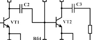
For example, a simple amplifier circuit with one transistor.
Input X1 plus (left or right channel), X2 minus. The sound signal is sent to electrolytic capacitor C1. It protects transistor VT1 from short circuiting, since transistor VT1 is constantly open using a voltage divider across R1 and R2. The voltage divider sets the operating point at the base of transistor VT1, and the transistor does not distort the input signal. Resistor R3 and capacitor C2, which are connected to the emitter of transistor VT1, perform the function of thermal stabilization of the operating point as the temperature of the transistor increases. Electrolytic capacitor C3 accumulates and filters the supply voltage. The BF1 dynamic head serves as an audio signal output.
Is it possible to understand this only by learning the designations of radio components without circuit design and theory? Unlikely.
The situation is even more complicated with digital technology.
What kind of microcontroller is this, what functions does it perform, what firmware and what fuses are installed in it? And the second microcircuit, what amplifier is it? Without datasheets and a description of the circuit, it will not be possible to understand its operation.
Study circuit design, theory and practice. Simply learning the names of the parts will not help you understand the circuitry. The designation of radio components can be learned on its own with practice and accumulation of knowledge. It all depends on the chosen industry. Signalmen have one circuit design, mobile equipment repairmen have another. And those who deal with sound will not really understand electricians. As well as vice versa. To understand another industry, its circuitry and operating principles, you need to immerse yourself in it.
Circuit diagrams are a kind of language that has different dialects.
Therefore, one should not create illusions. Study circuit design and assemble circuits.
Schematic diagrams help to assemble devices, and when studying the theory, to understand the operation of the device. Without knowledge and experience, a diagram is just a diagram.
Procedure for developing OSE
When creating a single-line electrical network project, you will need to comply with certain regulatory rules. In this case, the selection of individual circuit elements must be carried out in accordance with the PUE.
What information should the OSE carry?
The diagram intended to formulate a power supply project will definitely need to reflect:
- connection point to the power source;
- type of input device (automatic machine or distribution point) indicating the rated current;
- information about the meters used to account for electricity;
- brand, length, cross-section and number of current-carrying cores of cable lines;
- calculated voltage losses and load;
- the protective devices used;
- location of internal and external lighting networks.
Development stages
Before starting to develop a single-line electrical network project, you will need to obtain technical specifications. To do this, you will need to contact the municipal electrical network department. The technical condition determines the location of the facility’s connection to the power supply network, as well as the distribution boundaries of the future power supply project.
After this, you will need to visit the department of architecture and urban planning at your place of residence. In it, make a request for the issuance of a master plan for the land plot. This is necessary to accurately determine the location of the supply line from the connection point, excluding intersections with other engineering structures. You can also determine the length of the future cable line.
Procedure for connecting to electrical networks
At the next stage, the planned loads are calculated, with all the required elements displayed on a single-line diagram. At the final stage, all that remains is to approve the project and obtain permission to connect to the power supply network.
GOST requirements and design nuances
The construction of OSE is carried out in accordance with the requirements of GOST ESKD. For this, the following GOST numbers are used:
- 709-89 - current-carrying conductors, electrical equipment and contact connections;
- 710-81 — application of alphanumeric designations;
- 721-74 - elements of general use;
- 732-68 - designation of light sources;
- 755-87 - switching devices and contact connections;
- 702-2011 - rules for designing diagrams.
Alphanumeric designations in diagrams in accordance with GOST 2.710-81
When preparing a drawing, it is recommended to adhere to the following rules:
- Initially, a frame and a stamp of the established shape are drawn.
- If necessary, you can spread the drawing onto several sheets to make it easier to read. In this case, a list with continuous numbering is formed.
- The marking of circuit elements is carried out from the power source to the end consumer. For this purpose, capital Latin letters and Arabic numerals are used. The former indicate the phase of the alternating current, and the latter indicate the sequence of the circuit.
- Odd numbers are used to indicate positive polarity, and even numbers are used for negative polarity.
- Decoding the markings of the circuit components is performed on the left side of the drawing or directly above each element.
- The main parameters of the supply network, as well as consumers, can be included in a separate table. However, its size is not regulated.
- It is allowed to use free sections of the OSE to display the technical characteristics of cable lines in the form of text.
Symbolic graphic display of circuit components
To compile the OSE you will need to use certain conventions. Most of them are reflected by GOST ESKD 2.721-74, 2.709-89, 2.755-87 and 2.732-68 in separate tables.
Project verification and approval
After the development of the OSE is completed, the signature of the direct executor is placed on it. In the future, you will need to obtain approval of the project from a responsible specialist on the part of the supplier, who will verify the provided data.
The final stage will be obtaining permission to implement the project from the head of municipal electrical networks. Depending on the established staff of the specified organization, the checking and approving specialist may combine responsibilities.
Common wire designation
In complex electrical circuits, in order to improve the readability of the diagram, the conductors connected to the negative terminal of the power source are often not shown. And instead of them, signs are used indicating the negative wire, which is also called common or ground or chassis or ground.
Next to the grounding sign, especially in English-language circuits, there is often the inscription GND, short for GRAUND - ground.
However, you should know that the common wire does not have to be negative; it can also be positive. Especially often, the positive common wire was mistaken for the positive common wire in old Soviet circuits, which predominantly used transistors of p–n–p structure.
Therefore, when they say that the potential at some point in the circuit is equal to some voltage, this means that the voltage between the indicated point and the “minus” of the power supply is equal to the corresponding value.
For example, if the voltage at point 1 is 8 V, and at point 2 it is 4 V, then you need to install the positive probe of the voltmeter at the corresponding point, and the negative probe to the common wire or negative terminal.
This approach is quite often used, since it is very convenient from a practical point of view, since it is enough to indicate only one point.
This is especially often used when setting up or adjusting radio-electronic equipment. Therefore, learning to read electrical circuits is much easier by using potentials at specific points.
External connection E5
In the drawing, it is necessary first of all to indicate the product itself, its input and output components (couplings, clamps, etc.) and the contacts of cords and external installation cables connected to them, near which information about the connection itself is located.
The constituent parts of the plan are shown as quadrangles, and the input and output parts are shown as lines, segments and dotted lines. It is allowed to use simpler notation to construct the diagram.
How the harness connection is clearly indicated
Note! Connectors, clamps and other components are positioned in the same way as they appear on the product itself.
Introductory details can be placed in the form of iconic graphic symbols. The drawing must indicate the input, output or output parts that are present on the product. If these components are not included, then conventional symbols are used in the diagram.
It is allowed to write an explanation and name next to all components. As well as the necessary data from the documentation on the product. Cable products and cords are shown as separate lines. It is allowed to use markings for cable products, but its explanation is written strictly in the margins (name, cross-sectional area, power, number of cores inside).
You may be interested in this Features of an independent release
E6 GOST
Designation of wires and their connections on diagrams
Electrical wires perform the function of combining all electronic elements into a single circuit. They act as a “pipeline” - they supply electronic components with electrons. Wires are characterized by many parameters: cross-section, material, insulation, etc. We will deal with installation flexible wires.
On printed circuit boards, conductive paths serve as wires. Regardless of the type of conductor (wire or track), in the drawings of electrical circuits they are designated in the same way - a straight line.
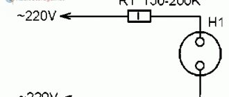
For example, in order to light an incandescent lamp, it is necessary to supply voltage from the battery using connecting wires to the light bulb. Then the circuit will be closed and a current will begin to flow in it, which will cause the filament of the incandescent lamp to heat up until it glows.
The conductor should be denoted by a straight line: horizontal or vertical. According to the standard, wires or live paths can be depicted at an angle of 90 or 135 degrees.
In branched circuits, conductors often intersect. If an electrical connection is not formed, then a dot is not placed at the intersection.
If an electrical connection is formed at the intersection of conductors, then this place is designated by a point called an electrical node. Several conductors can intersect at the same time in a node. Here I advise you to get acquainted with Kirchhoff's first law.
Conventional graphic designation of radio components
The basis of any electronic device is radio components. These include resistors, LEDs, transistors, capacitors, various microcircuits, etc. To learn how to read electrical circuits, you need to know well the graphic symbols of all radio components.
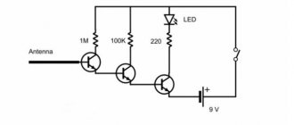
For example, consider the following drawing. It consists of a battery of galvanic cells GB1, resistor R1 and LED VD1. The conventional graphic designation (UGO) of the resistor looks like a rectangle with two terminals. In the drawings it is designated by the letter R, followed by its serial number, for example R1, R2, R5, etc.
Since an important parameter of a resistor, in addition to resistance, is power dissipation, its value is also indicated in the designation.
The LED UGO has the shape of a triangle with a line at its apex; and two arrows, the tips of which are directed from the triangle. One terminal of the LED is called the anode, and the second is called the cathode.
An LED, like a “regular” diode, passes current in only one direction - from the anode to the cathode. This semiconductor device is designated VD, and its type is indicated in the specification or in the description of the circuit. The characteristics of a particular type of LED are given in reference books or “datasheets”.