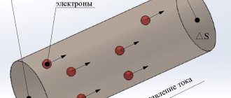
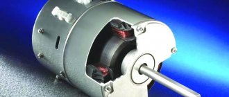
§5.6. DC motors. Main characteristics
Motors of independent and parallel excitation. The circuit diagram for switching on an independent excitation motor is shown inAn additional resistance Rd can be included in the armature circuit, for example a starting rheostat. To regulate the excitation current, a control rheostat Rр can be included in the excitation winding circuit. In a parallel excitation motor, the armature and excitation windings are connected to the same power source, and the voltage on them is the same. Consequently, a parallel excitation motor can be considered as an independent excitation motor at Uя = Uв.
Mechanical characteristics. The mechanical characteristics of engines are usually divided into natural and artificial. The natural characteristic corresponds to the rated supply voltage and the absence of additional resistance in the motor winding circuits. If at least one of the listed conditions is not met, the characteristic is called artificial. The equations for electromechanical ω=f(I i) and mechanical ω=f(M em.) characteristics can be found from the equilibrium equation of EMF and voltages for the motor armature circuit, written on the basis of Kirchhoff’s second law:
U i=E i+I i)(R i+R d), (5.35)
where R i is the active resistance of the armature. Transforming (5.35) taking into account (5.6), we obtain the equation of the electromechanical characteristic
ω=(U i-I i(R i+R d))/kФ. (5.36)
In accordance with (5.10), the armature current I I = M em./kF and expression (5.36) is converted into an equation of mechanical characteristics:
ω=Uя/ kФ – ( R I+ R d)/( kФ) 2) Mem. . (5.37)
This equation can be represented as ω= ω o.id.- Δ ω, where
ω o.id.=Uя/kФ (5.38)
ω o.id - angular speed of ideal idle speed (at Iа=0 and, accordingly, Mem.=0); Δ ω= Ma'am. [(Rя+Rд)/(kФ)2] – reduction in angular speed due to the load on the motor shaft and proportional to the resistance of the armature chain. The family of mechanical characteristics at rated armature voltage and excitation flux and various additional resistances in the armature circuit is depicted in.
The mechanical characteristics of engines are usually assessed by three indicators: stability, rigidity and linearity. The natural mechanical characteristic corresponding to (5.37) at Rd=0 is depicted by straight line 1. The mechanical characteristic is linear; deviation from the linear law can be caused by the armature reaction, leading to a change in the flux F. This characteristic is rigid, since when the load torque and, accordingly, the speed change, the excitation flux does not change. The rigidity of the characteristic decreases with the introduction of additional resistance into the armature circuit (straight lines 2 and 3 are artificial rheostatic characteristics). The characteristics are stable, since dω/dMem.
Iya= (Uya-Eya)/(R i+ R d)=(Uya -kωФ;)/( R i R d), (5.39)
increases. Accordingly, the electromagnetic moment increases up to a new value of the moment of resistance (transition from point A to point B on the mechanical characteristic). By analogy, based on (5.37), a family of artificial characteristics can be constructed for various values of Uya or F. The analysis of such characteristics will be done in the section of DC actuator motors (§ 5.7).
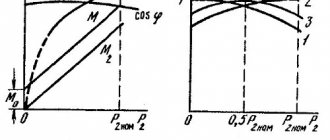
Performance characteristics. The operating characteristics of the engine are the dependences of the angular velocity ω, the electromagnetic Mem. and useful M2 torques and efficiency η from the useful mechanical power on the motor shaft P2=M2ω at the rated supply voltage and the absence of additional resistances (). However, for the motors under consideration, the performance characteristics are built not as a function of the useful power of the motor P2, but as a function of the armature current Iа. This is explained by the fact that in DC motors, the electrical power used for conversion into mechanical power is supplied through the armature circuit. The armature current of independent and parallel-excited motors, in which the speed weakly depends on the load, is almost directly proportional to the power P2. It is much easier to obtain equations for operating characteristics in terms of current Iа. Characteristics ω= f(Iя) and Mem.=а(Iя) can be constructed, respectively, based on equations (5.36) and (5.10). Without taking into account the armature reaction, these characteristics are linear; in real machines, under the influence of the armature reaction (change in F), the characteristics may turn out to be nonlinear. The useful component of the engine torque M2 is less than the electromagnetic torque by the value of the idle torque M0=(ΔPmech.+ΔPm)/ ω, where ΔPmech. – mechanical power losses (friction); Δ Pm – magnetic losses. The characteristics of the useful torque M2 and efficiency η begin from the real no-load point, which corresponds to the armature current Iао (Fig. 5.20, b). The efficiency curve has a typical character for all electric machines, because in the motor there are constant losses (ΔPmech.+ΔPm+UvIv), practically independent of the load (armature current), and variable losses in the armature I 2ya Rya.
Speed regulation. The angular speed of the motor at a constant moment of resistance can be adjusted (see (5.37)) in three ways: 1) armature - by changing the voltage on the armature winding Ui; 2) pole – change in magnetic excitation flux Fv; 3) rheostatic - changing the additional resistance Rd in the armature circuit. The regulating characteristics of independent excitation motors with armature and pole control methods will be discussed in detail in the section of actuator motors (see §5.7). With the rheostatic method, a significant current must be passed through the rheostats Rd (see) for a long time, which causes large power losses, therefore this method is uneconomical and is rarely used.
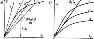
Start. In accordance with the moment equilibrium equation (2.29), the condition for starting the engine is the inequality Mn > Mst. If this condition is met, then when the engine is turned on, the rotor starts to move and accelerates to a steady state. Due to the fact that the rotor has a moment of inertia, it does not accelerate instantly - the speed increases according to a law close to exponential. Starting a DC motor is complicated by the fact that at ω=0 EMF EIa=0 and the starting armature current IaP= UIa/ RIa can be 10 - 20 times higher than the rated current, which is dangerous both for the motor (increased sparking, dynamic overloads) and for the power supply. Therefore, the most important indicators of the starting mode are the multiplicity of the starting current Kip = Ip/ Inom and the multiplicity of the starting torque Kmp = Mp/ Mnom. When starting, it is necessary to ensure the required multiple of the starting torque with the lowest possible multiple of the starting current. Direct starting is usually used with a starting current multiplicity of K iп?6. At a higher value of Kip, starting methods are used that ensure a reduction in current Iap either by applying a reduced voltage to the armature winding, or by introducing additional resistance into the armature circuit. The first method is used mainly when operating engines in automatic control systems with an anchor control method. The second method, called rheostatic, is most widespread in unregulated drives. The resistance of the starting rheostat Rп = Rд (see Fig. 5.19) is chosen so as to limit Ir to (1.4 - 1.8) Ir.nom for engines of medium power and to (2.0 - 2.5) Ir.nom for low power engines. As the armature accelerates, the armature current decreases and the starting rheostat is gradually removed.
Reversing. Reversing the motor is carried out either by changing the polarity of the voltage on the armature winding or on the field winding. In both cases, the sign of the electromagnetic torque of the MEM engine and, accordingly, the direction of rotation of the rotor changes.
Braking. For independent and parallel excitation motors, three braking modes are possible: regenerative braking, counter-switching braking and dynamic braking. When analyzing braking conditions, it is necessary to construct the mechanical characteristics of the machine in all four quadrants of the plane Mem, ω. To construct mechanical characteristics, you can use the same equation (5.37), taking into account the sign of Mem in different operating modes of the machine. Regenerative braking, or regenerative braking with energy released into the network, can be carried out at ω>ω o.d. In this case, the armature EMF Eя > Uя (see (5.6) and (5.38)), the armature current changes direction, the machine goes into generator mode and the electromagnetic torque becomes braking. The mechanical characteristic in the regenerative braking mode is the continuation of the mechanical characteristic of the engine in the II quadrant (ω>0, Mem (Fig. 5.21, a, Uя2я1).
At the moment the supply voltage decreases, the engine moves from point A of characteristic 1 to point B of characteristic 2, the moment Mem changes sign and the engine begins to brake to point C. Braking to a stop in this way is impossible and it is used mainly when braking at high speeds. The method is economical due to the possibility of transferring electrical energy to the network. Braking by counter-switching can occur in two cases: 1) if an external torque greater than the starting torque of the engine causes the armature to rotate against its natural direction of rotation (operation in the IV quadrant); 2) if the polarity of the voltage on the armature (or less often on the excitation winding) changes, and the armature, by inertia, continues to rotate in the same direction. Next, we consider the most common second case with a change in the polarity of the voltage at the armature. In this case, the armature current Iа=(-Uя- Eя)/ Rя changes direction and its value increases sharply, because Now voltage and emf act in the same direction. Therefore, when braking by counter-connection, an additional resistance Rd is necessarily included in the armature circuit. A change in the polarity of the voltage on the armature means that the sign of the ideal speed will also change. ω o.id, i.e. the mechanical characteristic will pass through the III quadrant (). At the moment of voltage switching, the engine moves from point A of the natural characteristic of motor mode I to point B of the rheostatic characteristic of braking mode 2, the torque Mem changes sign and an intensive decrease in ω begins. At point C, the motor speed is zero and it must be disconnected from the power source. If this is not done, then the rotor will begin to rotate in the opposite direction and will go into steady state at rheostatic point D or, if Rd is turned off, at point D' of the new natural characteristic 3, i.e. the engine will reverse. Dynamic braking is carried out by disconnecting the armature circuit from the direct current source U and closing it to some additional resistance Rd, usually called a braking rheostat (transferring switch K from the left to the right position).
In this case, the voltage applied to the armature, Ui=0, the armature current (see 5.39) Ia=-Eya/(Rya+Rd) changes direction and the electromagnetic torque Mem becomes braking. The kinetic mechanical energy stored in the rotating parts of the drive is converted into electrical energy, and the machine operates in generator mode, delivering electrical energy to the braking resistances. The equation of mechanical characteristics (5.37) at Uя=0 takes the form ω=-Мем(Rя+Rд)/(kФ)2. The mechanical characteristics of the braking mode are located in the II quadrant of the plane Mem,ω (, Rд2>Rд3). At the moment of switching, the engine moves from point A of the natural characteristics of the motor mode 1 to point B of the characteristics of the braking mode 2, the moment Mem changes sign and dynamic braking begins. The angular velocity decreases, but at the same time the braking torque also decreases quite sharply (transition from point B to C). In order to increase the braking torque, the additional resistance Rd is reduced (transition from point C to point D). Braking occurs to zero speed.
Motors of series and mixed excitation. In a series-excited motor (), the armature current flows through the excitation winding (Iв = Iя) and this in a certain way affects the main characteristics of the motor. In the absence of saturation of the magnetic circuit, it can be assumed that
Ф=KфIя, (5.40)
where Kf is the proportionality coefficient. Taking (5.40) into account, equations (5.10) and (5.37) take the form
Mam=KKфIя2, (5.41)
ω = (U/ √(KKfMem)) -(Rя+Rв/KKф), (5.42)
where Rв is the resistance of the excitation winding. The mechanical characteristic (dashed line) is soft, has a hyperbolic shape and ensures stable engine operation. The softness of the characteristic is explained by the fact that with an increase in load torque and a corresponding decrease in speed, the current and excitation flux increase. At high loads, saturation of the magnetic circuit begins to affect and the characteristic differs from the calculated one (solid line). The sequential excitation motor cannot be started without a load on the shaft, since at Mem → 0, the angular velocity ω → ∞. The quadratic dependence of torque on current makes it possible, with the same multiplicity of starting current, to obtain a larger starting torque from a series-excited motor than from an independent or parallel-excited motor. Starting, reversing, braking and regulating the angular speed of series-excited motors is carried out in the same ways as for independent and parallel-excited motors, taking into account the specifics of switching on the windings.
Mixed excitation motors, in their characteristics, occupy an intermediate position between independent and sequential excitation motors. The specific type of characteristics depends on whether the excitation windings are connected in accordance with or countercurrently (along the flow).
Back | Contents | Forward
Rated power consumed by the motor from the network
where is the rated mechanical power on the motor shaft, kW
-nominal efficiency, p.u.
Total power loss in the engine at rated load
Motor rated current
where is the rated voltage, V
Rated excitation current
where is the resistance of the excitation winding, Ohm
Rated armature current
We roughly assume that the electrical power losses in the armature circuit of a parallel-excited motor are half of the total power losses in the motor
Motor armature circuit resistance
Engine performance, at
Nominal angular mechanical speed of armature rotation
where is the rated armature rotation speed, rpm
Product of the constructive machine constant Ce and the nominal magnetic flux Fn
Torque equation
Electromagnetic torque of the motor
Mem = Pem / Ω,
which is driving and acts in the direction of rotation, is spent on balancing the braking moments: 1) moment M0, corresponding to the losses pmg, pd and pmx, covered by mechanical power [see equality (6) in the article “General information about direct current generators”] ; 2) Mv – load moment on the shaft created by the working machine or mechanism; 3) Mdyn – dynamic torque [see equality (7) in the article “General information about DC generators”]. Wherein
Mв = P2 /Ω
Thus,
| Mem = M0 + Mv + Mdyn | (1) |
or
| Mem = Mst + Mdin | (2) |
Where
Mst = M0 + Mv
is the static moment of resistance.
Under steady-state operating conditions, when n = const and therefore Mdin = 0,
| Mem = Mst. | (3) |
In what follows, we will omit the “um” index from Me. Usually M0 is small compared to Mv, and therefore we can approximately assume that under steady-state operation Mem = M is the useful torque on the shaft and is balanced by the torque Mv. You can also include the value M0 in the value Mv.
We point out that if we express P in kilowatts, and Ω in terms of the number of revolutions per minute nm, then there will be a relationship between P, nm and M in kgf × m
Voltage and Current Equation
In engines, the direction of action is e. d.s. the armature Ea is opposite to the direction of the armature current Ia (see the article “The principle of operation of a DC machine”), and therefore Ea is also called the counter-electromotive force of the armature. The voltage equation for the motor armature circuit can be written as follows:
| U = Ea + Ra × Ia. | (4) |
Here Ra is the total resistance of the armature circuit [see equality (15) in the article “General information about DC generators”]. In engine mode, always U > Ea.
From equality (4) it follows that
| (5) |
where, according to expression (3), in the article “Basic electromagnetic relations. Electromotive force of the armature and electromagnetic torque",
| Ea = ce × Фδ × n. | (6) |
Net mechanical power on the shaft
Electrical power loss in the armature circuit
Electrical power consumed by the motor from the network
Current consumed by the motor from the network
Engine efficiency
Performance calculation results
| 0 | 0,25 | 0,5 | 0,75 | 1,0 | 1,25 |
| 0 | 52,55 | 105,09 | 157,6 | 210,19 | 262,74 |
| 14 | 66,66 | 119 | 171,75 | 224 | 276,85 |
| 7,44 | 35,16 | 62,88 | 90,59 | 118 | 146 |
| 115,33 | 112,68 | 110,04 | 107,39 | 104,74 | 102,09 |
| 1101,86 | 1076,58 | 1051,29 | 1026,02 | 1000,74 | 975,46 |
| 0 | 5,92 | 11,56 | 16,93 | 22,02 | 26,83 |
| 0,01 | 0,224 | 0,716 | 1,485 | 2,533 | 3,859 |
| 2,27 | 8,41 | 14,54 | 20,68 | 26,81 | 32,95 |
| 10,32 | 34,21 | 66,09 | 93,98 | 121,87 | 149,75 |
| 0 | 0,704 | 0,795 | 0,819 | 0,821 | 0,814 |
Dependency graph I, M2 = f (P2)
Dependence graph P1 = f (P2)
Graph of h = f (P2)
Graph of n = f (P2)
Determining the resistance of the starting rheostat
Resistance of the starting rheostat, if the starting armature current is set
Mechanical characteristics of the engine at various additional resistances in the armature circuit