Bipolar power inverting amplifier circuit
The basic circuit of a bipolar power inverting amplifier looks like this:
Here we see two resistors and itself. We apply a signal to the input, and then remove the amplified signal from the output. As you can see, the non-inverting input of the op-amp is grounded. How does the scheme work? Here we see feedback. That is, the signal from the output is fed back to the input through resistor R2. Our amplifier is inverting, since the output signal is 180 degrees phase shifted relative to the input signal. This means that at the node where two resistors and the inverting input are connected, the output signal will arrive with a minus sign. Such feedback is called negative feedback ( NFC ) . It reduces the high gain of the op amp to the values we need.
In a NON-inverting amplifier, feedback is via voltage, and in an inverting amplifier, feedback is via current.
If you read the article about the op-amp, then you probably remember that if one of the inputs of the op-amp is connected to ground, then the other input has exactly the same potential. In this case, our non-inverting input is connected to ground, therefore, the inverting input will have exactly the same potential, that is, 0 Volts. Such an input is also called imaginary (virtual) earth . As Wikipedia says, “fake is false, counterfeit, false.”
The voltage gain of any amplifier is expressed by the formula
So what do we get in the end?
Input voltage from the formula above
But since our amplifier inverts the input signal, therefore, at the output we will have a voltage with a minus sign, that is, -Uout.
In this case, the current I2 will be expressed by the formula:
From here we find the gain
Since the input resistance of the inverting input is infinitely large, therefore, current will flow only through the circuit R1->R2. There cannot be two different currents in one branch, so it turns out that
As a result, our formula is reduced and we get
Circuit design using operational amplifiers. Part 2
In the previous article, we examined in detail the basic circuits of operational amplifiers and simulated their operation on “real” signals. This time we will continue to consider and simulate op-amp circuits and talk about buffers, adders and subtractors.
BUFFER CASCADE ON AN OPERATIONAL AMPLIFIER
The buffer stage, also called a signal follower, is a non-inverting operational amplifier covered by 100% voltage feedback:
Rice. 1 — Diagram of a buffer stage based on an op-amp
Since there are no resistors that set the gain factors, create voltage drops and current flow in the circuit, it is practically impossible to simulate it. We can only say that the voltage at the inverting input will always be set equal to the voltage at the non-inverting input, pulling the output of the operational amplifier along with it. Thus, the output of the circuit will always be the same signal as the input, and the gain of the circuit will always be equal to unity.
But why need a circuit that does nothing? Nobody needs such a circuit, and the buffer stage is designed to match the load with the signal source thanks to its very large (tending to infinity) input resistance and very small output resistance!
To be fair, it should be noted that by swapping the inputs we will not get an inverting buffer! For these purposes, you should use an inverting amplifier (discussed in the first article), setting its gain with resistors to -1.
VOLTAGE SUMMER ON AN OPERATIONAL AMPLIFIER
A voltage adder based on an op-amp, among all the circuits we are considering, in its basic implementation is closest to a complete cascade of an audio device - a signal mixer. Of course, this device is used not only in audio engineering. Adders are actively used in constructing circuits of measuring instruments, medical devices, RF and microwave signal processing devices...
The principle of operation of the adder is that all signals from all inputs are added by voltage and the already added ones are fed to the output of the circuit. In this case, the gain coefficient of both the adder itself and the attenuation coefficient of each individual signal can be set. The number of inputs of the adder is not limited, but not less than two (there is simply nothing to add one input).
Circuitry of the adder is implemented on the basis of an inverting amplifier based on an op-amp and is represented as follows:
Rice. 2 - Adder circuit on op-amp
The output voltage will be determined as the sum of the products of the input voltages and the gains formed by the resistances R1...Rn with the resistance Roс, and since the base for the construction is an inverting op-amp, the resulting output voltage will also be out of phase with the sum of the input ones:
Since we are not really theorists, but rather practitioners, let's check empirically! Let's assemble an adder for 3 inputs, with a gain of 5, while the gain of the second input should be 2. To do this, we will set the values for the resistors, based on the fact that Roc will be set to 10 kOhm: R1 = R3 = 2 kOhm (without attenuation), R2 = 4 kOhm (attenuation 2 times). Let's immediately set the input parameters of the signals: Uin1 = 3 V, Uin2 = 4 V, Uin3 = -2 V. Let's calculate the theoretical output voltage of the adder:
The diagram shows the input voltages, resistance values and currents:
Rice. 3 — 3-channel adder circuit
We calculate the currents flowing through the input resistances of the channels:
To determine the output voltage, we need to determine the voltage drop across the resistance Roc through which the current Ioc flows. The current Ioc itself can be determined using Kirchhoff's first law: the sum of the currents in a node is always equal to zero. Adding up all the input signal currents, we find the current Ios: Ios = I1 + I2 + I3 = 0.0015 + 0.001 - 0.001 = 0.0015 A. Next, we find the voltage drop across the feedback resistance: Uos = Ros * Ios = 10000 * 0.0015 = 15 V. The output voltage will be less by the voltage drop across the resistor Roc than the voltage at the inverting input of the amplifier. Since the voltage at the inverting input of the op-amp is 0 V, Uout = 0 - 15 = -15 V. This confirms the correctness of the circuit design and calculations.
VOLTAGE ADDER-SUBTRACTOR ON AN OPERATIONAL AMPLIFIER
The op-amp subtractor is the differential amplifier we considered. It is he who, by comparing two signals, finds and enhances the difference between them. But it only subtracts two signals, but what if the task requires subtracting 3 from 2 signals at once? Of course, modify the existing differential amplifier! To do this, we will add it to its inputs... Adders! In general, the subtractor circuit will look like this:
Rice. 4 - Adder-subtractor circuit on an op-amp
How will the output voltage of the circuit be determined? Quite simple (although the expression will not be very simple at first glance) - like the difference between the sums of the input signals of groups “a” and “b”!
Without diving into multi-level formulas, we can say that to determine the output voltage, the voltage of all inputs with the index “b” is enough and subtract the voltage of all inputs with the index “a” from this sum. The gain of the circuit is set by the value of the feedback resistance Roc.
Let's model a circuit that will have 2 inputs in each group. in this case, inputs “a” will receive 2 signals - 4 V and 8 V, and inputs “b” will receive 2 signals - 1 V and 3 V. Algebraically, we should get the voltage Uout = 1 + 3 - 4 - 8 at the output of the circuit = -8 V. Let's display the voltages, resistances and currents on the diagram and try to simulate the calculated situation.
Rice. 5 — Simulation of the adder-subtractor circuit
Let's simplify the existing circuit by replacing the voltage adders with single inputs:
Rice. 6 - Simplified adder-subtractor circuit
As a result of simplification, we got the usual differential amplifier, which was mentioned earlier and which was discussed in detail in the previous article. Let's calculate the currents and voltages of the circuit:
The voltage at the output of the circuit corresponds to the value we initially calculated -8 V, which confirms the correctness of the circuit and calculation method.
CONCLUSION
Next time we will look at a fundamentally separate class of devices based on operational amplifiers, which allows us to convert an analog signal into a digital one and vice versa, we will talk about comparators, parallel analog-to-digital converters (ADCs) and consider the implementation circuit of a digital-to-analog converter (DAC).
Example of an inverting amplifier
Let's see how our amplifier works in the Proteus electronic circuit simulator program. Here we are assembling a basic circuit with bipolar power supply
In Proteus it will look like this:
Here we took the value of resistors R2 = 10 kOhm and R1 = 1 kOhm, therefore, the gain of such a circuit will be equal to -10. The minus sign in this case simply inverts the amplified signal, which we see in the oscillogram below. The input signal is a pink waveform and the output signal is a yellow waveform. The output signal is in antiphase relative to the input, that is, it inverts it. Hence the name "inverting amplifier".
Inverting amplifier output saturation
Let's imagine this situation. We have an input alternating voltage with an amplitude of 1 V. The gain is 50. According to our calculations, we should receive a signal with an amplitude of 50 V at the output. But how do we get 50 V if the power supply to our amplifier is, say, +-15 V? We will not be able to receive an amplified signal with an amplitude greater than 15 V. Although the typical voltage drop in the internal circuits of real op-amps is about 0.5-1.5 V. That is, the maximum signal swing that we can get in this case at the output will be 27-29 Volts.
Although at present there are op-amps that still allow you to receive +-Up at the output. This property of some op-amps is called Rail-to-Rail. Literally translated “from rail to rail” or “from tire to tire.” There are parameters such as Rail-to-Rail input. Here we can supply signals up to the input of the op-amp. Sometimes the datasheet stipulates whether this parameter can be approached from the negative or positive power bus. There is also a Rail-to-Rail output. Here at the output we can get the voltage +-Up. If the amplified output signal does not fit into this range, it will be clipped. This property of an op-amp is called output saturation . That is, we must always remember that if the amplitude of the signal exceeds + - Upit of the amplifier, then such a signal at the output will be cut off at this level.
Let's demonstrate this in the Proteus simulator. So, let's apply a sinusoidal signal with an amplitude of 1 V to the input, and make the gain 20 by selecting the necessary resistors. That is, according to our calculations, we should get a sine with an amplitude of 20 Volts. Let's look at the oscillogram
We fed a sinusoid to the input, but at the output we received a sinusoid with cut off tops and an amplitude of 14 V. One cell in this case is 2 V. As you can see, we cannot get a signal with an amplitude of more than +-Upit. Always remember this, especially when designing electronic devices.
TDA2030 as a voltage repeater
For example, consider the TDA2030 chip, because the other two are its more powerful brothers. The microcircuit was originally developed and used in sound amplifiers. The vast majority of household amplifiers, especially 2.1 and 5.1 systems, are built on this chip. What is logical and understandable is that the chip is cheap and at the same time has good characteristics.
The microcircuit is implemented in a five-pin package and requires a minimum of parts for operation. When switched on according to a repeater circuit, only power supply capacitors are required for normal operation. It is better to also leave a resistor at the input to tie the input to ground at a constant voltage, although it is not necessary.
Standard circuit for connecting a microcircuit as an audio amplifier:
In the standard connection of the microcircuit (shown above), proposed by the data shield, the gain is set to about 20. In this case, the operating frequency band is limited by the same data shield at 140 kHz. However, when operating in a voltage follower circuit with unity gain, the microcircuit can operate up to frequencies of 0.5...1 MHz. At least the microcircuit performed well when operating at a frequency of 100 kHz, supplied from a sinusoidal signal generator on the Wien bridge, to amplify the output of which it was used.
Elegant, beautiful, and most importantly, it works. The microcircuit heats up considerably and it is advisable to use a radiator with sufficient surface area. A PC processor heatsink is perfect. However, heat dissipation depends on the operating mode and load resistance. It is not recommended to turn on the microcircuit without a heatsink.
In the original version, the microcircuit is powered by a stabilized voltage of ±9 Volts to ensure stability of the signal amplitude. The microcircuit was supposed to operate with a power of 2-3 Watts; for this reason, power stabilization was performed on banks 7809 and 7909, capable of providing current up to 1A (subject to the presence of radiators). The supply voltage range for the TDA2030 microcircuit is ±6 ... ±18 Volts .
Bias Current and Output Bias
The inputs of a real op amp draw a small current called bias current . In English datasheets it is called Input Bias Current . If the input circuits of the op-amp are built on bipolar transistors, then such a bias current will be somewhere around several tens of nanoamps, in contrast to the op-amp, where the input circuits are built on field-effect transistors. In input circuits built on field-effect transistors, the bias current is estimated in tenths of picoamps. Therefore, the bias current is very important specifically for op-amps, whose input circuits are built on bipolar transistors.
Why is bias current so important? Let's look at the diagram again
Even if we do not apply any signal to the input, we will still have some small constant voltage at the output. Why is this happening? The bias current is to blame for everything. It creates a voltage drop across the feedback resistor. In this case, it is resistor R2. And as you know, greater voltage drops at higher resistance. That is, if the value of resistance R2 is very large, then a large voltage will drop across it, which will go to the output of our op-amp.
Let's say the bias current is 0.1 μA, and resistor R2 = 1 MOhm, then what voltage drop will be across the resistor in this case? Let's remember Ohm's law: I=U/R, hence U=IR= 0.1 V. That is, at the output we will already have a constant voltage of 0.1 V! By applying a useful signal with a bias current of 0.1 μA to the input of such an amplifier, at the output this signal will be amplified and summed with a constant component of 0.1 V. In our case, the zero level is shifted. It’s clear in the figure below.
Schmitt trigger
As stated above, to eliminate false positives of the comparator, known as “contact bounce,” it is necessary to use a comparator circuit with a hysteresis loop, which is called a Schmitt trigger.
In one of the articles I talked about a Schmitt trigger made on transistors. It is characterized by the fact that, unlike a comparator, it has a so-called hysteresis loop. That is, the comparator switches from a high voltage level to a low one at the same input voltage, and the Schmitt trigger has two switching levels (thresholds)
. This difference is illustrated in the image below.
The voltage levels at which the Schmitt trigger switches are called the upper level (threshold) of the trigger UVP and the lower level (threshold) of the trigger UNP.
To implement a Schmitt trigger, op-amps are used that are covered by positive feedback (POF), which is implemented by applying part of the output voltage to the non-inverting input. Schmitt trigger circuit is shown below
Schmitt trigger on an operational amplifier.
The operation of a Schmitt trigger is in many ways similar to the operation of a comparator, only unlike it, in a trigger the reference voltage is not constant, but depends on the difference between the output and reference voltages, that is, it has different values.
Consider an inverting Schmitt trigger. In the original input voltage does not exceed the upper trigger level UVP, so the output has a positive saturation voltage UNAC+ (approximately 1 - 2 V below the positive supply voltage UPIT+). When the input voltage reaches the upper switching threshold UVP, the output voltage will sharply drop to the level of the negative saturation voltage UNAC- (about 1 - 2 V above the negative supply voltage UPIT-). The upper level of the Schmitt trigger switching voltage is given by the following expression
Then the trigger remains in a stable state until the input voltage becomes less than the lower operating threshold UNP, and a positive saturation voltage UNAC+ is established at the trigger output. The lower trigger threshold is determined by the following expression
Thus, the hysteresis loop will depend on the ratio of resistors R2 and R3, and the width of the hysteresis loop UGIS is determined by the difference between the upper response threshold UVP and the lower response threshold UNP
Schmitt triggers on op-amps are the basis for constructing various pulse generators, therefore the most important characteristics of op-amps operating in pulsed circuits is the speed, which depends on the response delays and the rise time of the output voltage.
Ways to deal with bias current
In some cases, the bias current can be neglected if it does not greatly affect your signal requirements. But if, nevertheless, you are developing any precise device, where the output signal must strictly fit into the technical specifications, then in this case you can resort to the following methods:
1) Place a small value resistor in the feedback circuit.
At low resistance, low voltage drops. Consequently, the output will already have a lower constant voltage. The standard range of resistors is from a few kiloohms to 50 kOhms.
2) Introduce a compensating resistor into the circuit
In this case, it will be determined by the formula:
If, nevertheless, the output signal meets your expectations even without RC, then it is better not to install it, since any resistor introduces noise distortion into the signal. Why add noise to the circuit once again?
3) Use an op-amp with input circuits built on field-effect transistors , or select an op-amp with low bias currents, fortunately now the production technologies of such op-amps have made great strides forward.
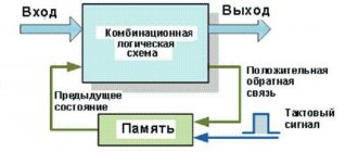
Op amp feedback
As I already mentioned, operational amplifiers are almost always used with feedback (OS). But what is feedback and what is it for? Let's try to figure this out.
We encounter feedback all the time: when we want to pour tea into a mug or even go to the toilet for a small need.
