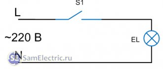
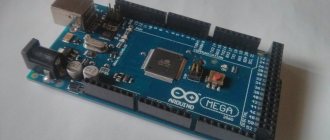
In modern households, most devices (light bulbs, TVs, air conditioners, etc.) are powered by AC voltage. We can control the on and off of these devices using Arduino board and relays, these ways of controlling home electronic devices have been discussed on our website in home automation projects. But if we not only need to control the processes of turning on/off devices, but also need, for example, to regulate the brightness of a lamp or the speed of a fan, then here we need to use phase control methods and static switches like triacs (TRIAC) to control the phases of AC voltage current
In this article we will look at creating a light intensity controller (dimmer) for an AC lamp based on an Arduino board and a triac. To switch the modes of the AC lamp, we will use a triac (TRIAC), a fast-acting electronic switch best suited for this type of project.
On our website you can also see projects in which light intensity adjustment was used:
- LED intensity control on the AVR ATmega32 microcontroller;
- automatic control of LED brightness using Arduino;
Zero crossing detection technique
To control AC voltage, the first thing we must be able to do is detect zero crossings of the AC signal. Therefore, at every moment in time when this signal passes through zero, we must switch the triac. The moment of zero crossing of the AC signal is shown in the following figure.
The principle of operation of a triac
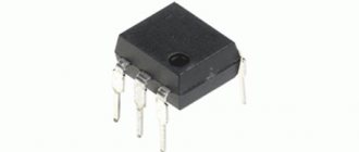
A triac (symmetrical triode thyristor, in English TRIAC) is an AC switch with three terminals that can be switched by applying a gate pulse to its control terminal (gate). But unlike other similar switches, which conduct current in one direction, a triac can control current in both directions. In our project we will use a BT136 triac.
The principle of controlling an AC triac is shown in the following figure.
As shown in the figure, we can switch, for example, a triac at an angle of 90 degrees by applying an unlocking pulse to its control terminal. In this case, we will supply current to the lamp only during half the time of the positive half-wave of the signal (time t1 on the graph), accordingly, the lamp will burn at half power. By decreasing or increasing this time we can make the lamp burn brighter or dimmer.
The frequency of the AC signal in our network is 50 Hz, respectively, the period of the signal is 1/f = 20 milliseconds. This means that half the period will be equal to 10 ms. Therefore, we can change the time t1 in the above graph to control the brightness of the AC lamp in the range from 0 to 10 ms (10000 μs).
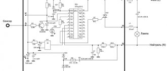
Network dimmer 220V on a microcontroller
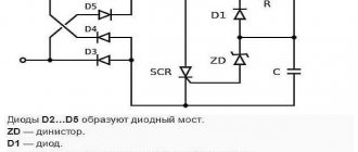
| Today I will share the results of my experiments in the field of controlling loads connected to a 220 volt household network. Namely, we will do dimming - we will smoothly light and extinguish an incandescent light bulb using a microcontroller. At first glance, there is nothing complicated here - we use PWM and adjust it to our satisfaction. But do not forget that the voltage in the outlet is variable, which means that this will be a little more difficult to do. Next there will be a little theory, a diagram and a control method. When working with high mains voltage, be careful and attentive! Do not touch exposed areas of the circuit under any circumstances. So why can’t we use a simple PWM signal in this case? As you know, in the socket we have an alternating voltage of a sinusoidal shape, as in the figure below. If you use control using PWM, the switch through which the signal is controlled (for example, a triac) will open and pass pieces of a sinusoid having different powers into the load. As a result, no smooth regulation will be possible, but there will be a disordered output signal: In order to avoid this, we must know when to turn the triac on and off, that is, bind the control signal to the controlled one. How? It’s simple, it’s enough to know when the signal passes through 0. Knowing where each next half-wave begins, we can open the key at the right moments, thereby giving the same power to the load. And by changing the time that the control key is in the open state, we can smoothly change the power output. The moment the mains voltage passes through 0 can be determined using an optocoupler. In order to detect the beginning of each half-wave (both negative and positive), we connect the optocoupler via a diode bridge. Thus, at the output of the zero detector we receive short positive pulses at the moment when the voltage in the network passes through 0. For clarity, I will give a picture from a virtual oscilloscope of a simulated circuit in proteus. The original signal (~220V) is shown in blue, the signal after rectification by a diode bridge is in red. Pulses at the output of optocoupler U3 are shown in green. The signal from the zero detector can be connected to the external interrupt input to catch the beginning of a new half-wave, and then open the triac U4 (I used BT16-600) for the required time. For optocoupling I used an optosimistor MOC3022 (U2). All that remains is to calculate the time for which the triac needs to be opened. At a mains voltage frequency of 50 Hz, the half-cycle time (the duration of one half-wave) will be 0.01 seconds. That is, if we open the triac for 0.005 seconds, we will skip half a half-wave, the power will be 50%, if we open the triac for 0.01 seconds (or more), we will skip the entire half-wave and the output power will be 100%. Here I think everything is clear. code in Bascom-AVR $regfile = "attiny2313.dat" minimum heat medium heat maximum heat and not a big video Controlling a light bulb method is of course not limited, the same method can be used to control other loads - heaters, motors, etc. | |
| Category: Useful information | Added: 04/26/2013 | |
| Views: 83285 | Comments: 65 | Tags: dimmer | Rating: 4.9 / 11 |
| Total comments: 65 | 1 2 3 » |
| 0 63 exersizze (12/28/2016 10:50) [Material] Butsun , optosimistors with a built-in zero detector, such as MOS306x, are not suitable for adjusting the incandescence of lamps... |
| +1 Spam 62 For those who are interested... connecting the load to the MK... useful) And there is a trick, if you use MOS3063, then we don’t need to catch zero... https://eugenemcu.nichost.ru/articles/applications/268-mcu-triac |
| 0 Spam 61 Thank you) I understood the principle of operation, but I didn’t understand where exactly the number 195 came from, now I understand that they picked it experimentally.. I got a minimum of 147, and at 146 it’s already in full swing.. |
| 0 60 exersizze (09.12.2016 13:53) [Material] pchela5 , well, this is in wartime, but in peacetime everything is approximately)) I found GOST 32144-2013 which says |
| 0 Spam 59 > A half-wave in our power grid lasts approximately 10 ms. In wartime, the sine value can reach three! © How about that? Networks must maintain 50 Hz, otherwise desynchronization may occur and everything will be covered with a copper basin. |
| 0 58 exersizze (09.12.2016 12:43) [Material] To understand where the number 195 comes from, you must first understand the principle of operation: when a new half-wave begins (the current has passed through zero), the timer begins to count until it overflows and after that the triac opens. If we put the value 255 in it, then it will overflow almost immediately and the triac will be open all the time until the current passes through zero again. In short, the triac will transmit half a wave completely. On the next half wave everything will happen again. Now let's decrease the starting value of the timer. This means that more time will pass between the current passing through zero and the timer overflowing, but in order to obtain the minimum heat, it is necessary for the timer to overflow before the half-wave that started the timer ends
|
| 0 Spam 57 Why is the minimum heat at 195? How much minimum can Wt be underestimated? |
| +1 Spam 56 add buttons for example: pinc.1=input pinc.0=input instead of If N = 1 Then 'smoothly turn on the lamp Incr Wt 'increase to the maximum value If Wt = 255 Then N = 0 End If Else 'smoothly turn off Decr Wt 'reduce to minimum value If Wt = 195 Then N = 1 End If End If Write if pinc.0=0 then decr Wt end if if pinc.0=0 then incr Wt end if |
| 0 Spam 55 Dear author!!! Help me remake your program so that you can use the +, - buttons to control the output power. And for some reason your program does not want to be modeled in Proteus. Help me please!!! Thank you in advance. |
| +1 Spam 54 My message from 18:33 is resolved. |
| 0 Spam 53 Hello, friends! Help me rework part of the program from this example so that the light bulb does not go out after it lights up, but remains on. |
| 0 Spam 52 Write on the forum, they will help you. |
| 0 Spam 51 Tell me what exactly, I’ll throw it away |
| 0 Spam 50 I already found your version https://bascomavr.3bb.ru/viewtopic.php?id=1113 the project works in Proteus, it’s a pity that the source code contains all the most interesting things in assembler, but I don’t understand it at all:(. from here the firmware works in that - the same project, until I start converting it to control buttons and UART. I don’t understand what the problem is |
| 0 Spam 49 Give me an email and I’ll send you a working version. |
| 0 Spam 48 “It’s still not possible to turn on the simulation, i.e. the simulation works for a couple of seconds then stops: https://dl.dropboxusercontent.com/u/52618061/Proteus.png" same parsley the simulation does not work(( |
| 0 Spam 47 Would you like to add a simulation, I have one ready for phases 1 and 3? |
| 0 Spam 46 dossalab, it is possible, but you will have to select the frequency so that the timer overflow time remains the same (unlike the 8-bit “zero timer,” Timer1 counts up to 65535). I highly recommend checking out this https://decada.org.ru/project/lessons/bascom_avr/10/ |
| 0 Spam 45 Is it possible to transfer the device to Timer1? And how? |
| 0 Spam 44 Here https://forum.easyelectronics.ru/viewtopic.php?f=14&t=17314 is an interesting circuit, if you control the field switch with a PWM signal, you will get a picture like this but with very narrow periods, much less than the frequency. https://avrproject.ru/dimmer/sinuspwm1.png |
| 0 Spam 43 emmgold , Why so? |
| 0 Spam 42 And if you increase the PWM frequency by a factor of 100. And you don’t need to worry. |
| 0 Spam 41 Still, it’s not possible to turn on the simulation, i.e. the simulation runs for a couple of seconds then stops: https://dl.dropboxusercontent.com/u/52618061/Proteus.png https://dl.dropboxusercontent.com/u/52618061/noname1.hex |
| 0 Spam 40 Proteus has tools for generating various signals, including sine
|
| 0 Spam 39 Is it possible to attach the Proteus project archive to an article? Just starting to get acquainted with microcontrollers and Proteus - a lot of questions... Tell me, how do you supply alternating voltage to the circuit in Proteus? |
| 0 Spam 38 but really) thank you! I'll fix the schedule. |
| +1 Spam 37 “If you use control using PWM, the switch through which the signal is controlled (for example, a triac) will open and pass pieces of a sinusoid having different powers into the load. As a result, no smooth regulation will be possible, but there will be a disordered signal at the output.” It will be so, but not as shown in the picture. The triac will open with the very first pulse and will not close until the current crosses zero. |
| 0 Spam 36 And another note regarding engines. The only thing, well, besides heaters and light bulbs, and even then not all of them :), that is more or less “calm” about phase-pulse regulation, is commutator motors. Everything else will strongly resist this regulation |
31-60 61-65
Add comments can only registered users. [Registration | Entrance ]
Project diagram
The circuit of the light intensity regulator (dimmer) on Arduino and a triac is shown in the following figure.
The connection diagram of the triac and optocoupler is shown in the following figure.
We assembled this circuit on a perforated board, we got the following design:
We also placed the MCT2E optocoupler and its connections on a perforated board and connected it to a step-down transformer.
The complete design of the entire project looks like this:
Creating a Project
File, new project: File -> New Project
Select the desired MK: STM32F103C8
We turn on the debugger: System Core -> SYS -> Debug: Serial Wire The clock frequency (by default 8 MHz) is not changed.
Click on any convenient pin (for me it’s PB12 ) and select GPIO_EXTI (External Interrupt), for convenience it can be called AC_Zero ( RMB -> Enter user label) :
We configure an external interrupt ( GPIO mode -> External Interrupt Mode with Rising edge trigger detection ), we need to enter it on a falling edge (transition from low to high level) - for a circuit with decoupling. For a circuit without decoupling, select on both edges ( GPIO mode -> External Interrupt Mode with Rising/Falling edge trigger detection ).
Any name and for Keil : Project Name: zero_crossing Toolchain/IDE: MDK-ARM, Min Version: V5.27
Generate code and open the project: GENERATE CODE -> Open Project
Testing the project's operation
The following three pictures show the 3 levels of dimming for an AC lamp.
1. Small adjustment step.
2. Medium adjustment step.
3. Maximum adjustment step.
Materials
Option 1
For convenience, you should divide your shopping list into several main items, depending on what we will use certain tools for. So, you will need to collect:
- Detector for tracking zero crossings. For this part of the project you will need an H11AA11 with a pair of 10k ohm resistors, as well as a 400 volt bridge rectifier and another pair of 30k ohm resistors. For convenience, it is worth purchasing 1 connector, as well as a 5.1 Volt stabilizer.
- Driver for lamp. Here a simple LED will be enough, as well as a MOC3021 with a 220 Ohm resistor (more is possible), as well as a 470 Ohm and 1 kOhm resistor, and one triac, the TIC version will do. You can also buy another connector.
- Auxiliary elements. Of course, when soldering you cannot do without wires and a piece of PCB 6 by 3 cm.
When you have collected all the necessary elements, the time for soldering will come, therefore, in addition to the above, you will also need a soldering iron and rosin with soldering. You can draw and make the board yourself or use a special printer, if available. Options for the location of paths can be found on our website or you can design everything yourself, according to your wishes.
Option 2
For our second alternative we will need:
1x - 330 Ohm resistor 2x - 33K resistor 1x - 22K resistor 1x - 220 Ohm resistor 4x - 1N4508 diodes 1x - 1N4007 diodes 1x - Zener diode 10V.4W 1x - Capacitor 2.2uF / 63V 1x - Capacitor 220nF / 2 75V 1x – Arduino / Arduino 1x - Optocoupler: 4N35 1x - MOSFET: IRF830A 1x - Lamp: 100W 1x - Power supply 230V 1x - Socket 1x - Soldering board and soldering kit