Serial and parallel connection of two or more light sources
In order to connect the simplest incandescent light bulb, as in principle any other, you need to connect one contact to phase and the other to zero, the most common alternating voltage in the CIS countries, 220 volts.
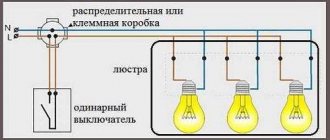
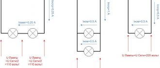
Parallel connection of lighting devices means connecting two or more sources of light flux in parallel, that is, some lamp contacts are connected only to phase, and all others only to zero, as shown in Figure 1.
A current will pass through each light bulb, which will depend on its power, just as the brightness of the light flux emitted by them will also depend on the power of each lamp. Naturally, the current I will be equal to the sum of all three currents, so the cross-sectional diameter of the main conductors should be chosen according to it. This connection is considered the most common and acceptable, since it will be possible, if necessary, to add light sources in the future and they will not affect those already installed.
With a series connection shown in the figure, the current flowing through one light bulb will depend on the power of each light source, and the voltage on them will be divided by the number of lamps and, for a given input voltage of 220 volts, will be equal to 110 volts on each light source.
This connection must be made with lamps that have equal power. This can be seen using the example of two incandescent lamps. Since if you connect one lamp of 20 Watt, and another, for example, of 200 Watt, then the lamp with a lower power will immediately fail, since the same current will pass through it as in the second lamp with a power of 200 Watt, and this is 10 times its face value. This connection can be used to increase the service life of incandescent lamps, for example, in entrances and staircases. By connecting two lamps of 220 volts and a power of, for example, 60 watts each, they will burn at half power and will last a very long time. Please note that this is only possible when connecting incandescent lamps. Connecting two or more LED lamps (luminaires) and energy-efficient lamps in series is not practical, since they already have a fairly long service life.
Connecting a lamp to one switch or several
How to connect a lamp through a switch? The main nuance when connecting is that the neutral power wire is directly connected to the 220 volt network, and the phase is broken through the switch. This is done so that you can safely solve problems with the lamp socket by turning off only the switch. If two switches are connected in series, then only when both keys are pressed will the lamp light up. These types of connection of light switches are very rarely used, only under certain individual conditions.
More interesting is the connection of the so-called pass-through switch.
The essence of this circuit for connecting one lamp is that the lamp can be turned on and off from both the first and second switches, regardless of the position of each of them. For example, this is convenient, say, in a long corridor, when entering it, a person presses the switch key 2, and calmly walks along the illuminated room, having reached the end of the corridor, there is no need to return to turn off the light, but he can lightly press switch 1, installed at the end corridor, turn off this light source. With this connection, the phase also passes through the switches.
Improving lighting by installing a motion sensor
The main function of installing a motion sensor and connecting it to the lighting system is to automatically turn on the lighting without pressing the light switch button. That is, a person entered the room or into the sensor trigger zone and the light turned on; after leaving, the light turned off on its own (automatically). When choosing a motion sensor, you must first take into account the maximum power of the lighting lamps.
The connection diagram for the motion sensor is also not particularly difficult. It can be installed with or without a switch. Simply, when the switch contact is turned on, the motion sensor is removed from the lighting network, and the lighting device is turned on directly without a sensor.
In any case, when working with voltage, be sure to comply with safety requirements, and in particular:
- check the presence and absence of voltage on live elements that a person touches during installation;
- lighting power supply circuit breakers must be locked;
- carry out work with proper tools.
Types of lamps and connection diagrams
Connecting the incandescent lamps shown above is not particularly difficult. But the circuit of halogen and fluorescent lamps has some differences.
Halogen
Low-voltage power supply increases the safety of light sources. However, the brightness remains the same. Halogen lamps can be used with step-down transformers of 6, 12 and 24 V (Fig. below).
Halogen lamp connection diagram
The 220 V voltage is supplied to a small-sized electronic transformer, which can even be built into the switch housing. Low-voltage halogen lamps are often used in suspended ceilings. They are connected in parallel and connected to a transformer. The photo below shows a block diagram with two transformers. A voltage of 220 V is supplied to them through a distribution box. The neutral wire is indicated in blue, and the phase wire is indicated in brown, with a switch inserted into the gap.
Connection diagram for halogen lamps
Groups of lamps are connected to each other in parallel in a distribution box, after which the supply wires are branched into the primary windings of the transformers.
The lamps are connected to the 12 V secondary winding in parallel with each other. Terminal blocks are used to connect them (not shown in the diagram).
The low voltage output wire should not be longer than 2 meters. Otherwise, voltage losses increase and the lamps will glow worse. It will be better if you calculate the voltage for all lamps.
Calculation example
An example of calculating the voltage on light bulbs depending on the losses in the wires is as follows. With a supply voltage of V=12 V, 2 light bulbs with resistances R1 = R2 = 36 Ohms are connected in parallel to the transformer. The resistances of the supply wires to them are equal to r1 = r2 = r3 = r4 = 1.5 Ohms. You need to find the voltage on each light bulb. The diagram is shown in Fig. below.
Losses in light bulb power wires
The voltage on the first and second bulbs will be:
V1 = VR(2r + R)/(4r 2 +6rR + R 2) = 10.34 V,
V2 = VR 2 /(4r 2 +6rR + R 2) = 9.54 V.
The calculation shows that even small resistances of the supply wires lead to a significant voltage drop across them.
The total load in the circuit is maintained at 70-75% of the maximum so that the transformers do not overheat.
Luminescent
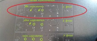
The disadvantage of fluorescent lamps is the flickering effect, which impairs the perception of light by the eyes. Modern electronic ballasts (ballasts) solve this problem, but their price is higher. To reduce ripple when using an electromagnetic ballast, a two-lamp connection circuit is used, where the phase of one of the lamps is shifted in time. As a result, the total luminous flux is leveled out.
In Fig. Below is a diagram of a split-phase lamp. Two lamps are connected to an alternating voltage network in parallel. They both contain inductive ballasts (L1) and (L2). But an additional ballast capacitor (Sb) is connected to the lamp (2), thanks to which a current phase shift of 60 0 is created.
Application of junction box
Cables and wires do not go directly from the panel to electrical appliances, from switches to light bulbs. All outgoing and incoming lines of electrical equipment are found in specific installation units called branch boxes. There they communicate in a certain way.
The following article will introduce you to the rules for installing junction boxes, also called junction boxes, branch boxes, or in electricians' slang, junction boxes. We recommend that you read the useful material.
Most often, boxes have empty space inside. The wires of different lines are then connected to each other using twists. To ensure reliability, it is recommended to treat the tails of the connections with special welding. Copper conductors can simply be soldered.
Before laying inside, open contacts are insulated from each other with cotton tape. You can screw special insulating clamps onto the twisted wires. Here, insulating tape is no longer needed.
If the box is equipped with screw terminals, the contacts are then made using them. Such devices allow you to connect aluminum and copper conductors. Clamp terminals can be used, but this is only if there is sufficient space for laying the ends of the wires connected by them.
Pros and cons of dual connection
An experienced electrician begins any project to improve a lighting system by optimizing the use of all electrical devices combined into one chain.
An example of an optimized circuit is the traditional lighting arrangement of the “toilet + bathroom” block. On the corridor side, one switch is usually installed, but with two keys.
Thus, the lamp in the bathroom is controlled by one key, and the light bulb in the toilet is controlled by a second. With one movement of your hand, you can perform two actions at once, turning off the lights in one room and turning on the lights in the next one, which is very convenient.
If the switch is installed in the wall between two parts of the bathroom, then choosing a key will not be difficult - it will be located on the side of the desired room
Installing a common switch for two rooms is advisable if they are located nearby. For rooms remote from each other, it is reasonable to use separate electrical installations.
A double switch may also be required when installing a chandelier or sconce with two bulbs. Separate control expands the functionality of the lighting device and allows you to increase or decrease the combustion intensity.
If you press one key, the lighting will be inadequate; when you press both keys, it becomes twice as bright.
To save energy, it is not necessary to use both bulbs at the same time. To create a relaxing atmosphere, it is enough to turn on only one of them
As you can see, the ability to connect a double switch to two separate light bulbs makes it easier to control lighting fixtures or adjust light intensity. When installing a single device for two rooms, not only electricity is saved, but the number of installation materials and devices is reduced.
Installation Safety Precautions
Here is a set of some standard rules to avoid trouble when installing lighting fixtures:
- The switch cannot be set to “zero”; it must always break the “phase”. Only in this case the switch is in the “off” position. allows you to carry out any repair work on the lamp, including replacing it, without cutting off power to the entire house.
- When making a twisted connection of wires in a junction box, under no circumstances should aluminum and copper wires be connected to each other. Metals with different potentials form a galvanic couple; the contact will weaken over time and begin to “spark.” Sometimes this leads to fires.
- Before starting work, you should stock up on a tester to determine the phase wire and, just in case, thick rubber gloves.
- You should not cover open wiring (either double insulated or triple insulated, it doesn’t matter) with paper wallpaper or other flammable finishing materials.
- Do not use used wiring. It is unknown what loads it was subjected to in the past, and it is impossible to check the condition of each core inside the braid along its entire length.
Transmitter connection option
Instead of connecting two light bulbs to a 220 V network, you can connect lighting fixtures to the network using 12 V frequency converters. Such devices conduct electric current to several lamps with a short pause of 1-2 seconds. At the same time, lighting devices receive electricity smoothly, without a sharp increase in load.
When can you connect the converter:
- for supplying current to incandescent lamps;
- for providing electricity to halogen light bulbs.
The switch is installed in the circuit before the converter. Otherwise, the contacts may burn out. This should happen because the current is greater at low voltage. In addition, the converter provides a slight delay in the incoming voltage. If a breaker is added after the switch, then the gradual, smooth start of the light bulbs will not be ensured. Thus, the whole point of including the converter in the circuit is lost.
If a two-key switch is mounted, then you will need to connect 2 converters. Power will have to be supplied to it through a second line. “Zero” will remain common.
Pass-through switches
The walk-through switches are not much different in appearance from simple switches. It has a housing, three terminals for connecting wires, 1 or 2 keys. As for the crossover switches, they have 4 terminals for connecting electrical wires. If you need to control two groups of lamps on one luminaire, use only pass-through switches with two keys.
Connecting a two-key switch to two light bulbs is not difficult. Such devices have 6 terminals for connecting wiring. As for conventional switches, they have only 3 terminals. Cross connectors have 8 terminals for connecting wires.
As for the internal design features, a circuit consisting of two lines is connected to the pass-through switch. Regardless of the position of the key, one line will always be closed and the other open. It turns out that when you connect a two-key switch to two light bulbs, the circuit that passes through it does not open. This can be seen in the diagram given in the article.
How to connect a chandelier with 2, 3, 4 or more wires with your own hands, diagrams
After you have drawn up a plan for the placement of spotlights on the ceiling, in the cabinet lighting, you have to think about their electrical connection. How to connect spotlights, according to what diagrams, what wires and cables - more on all this later.
Expert opinion
Viktor Pavlovich Strebizh, lighting and electrical expert
Any questions ask me, I will help!
After you have drawn up a plan for the placement of spotlights on the ceiling, in the cabinet lighting, you have to think about their electrical connection. If there is something you don’t understand, write to me!
Serial connection
You can connect spotlights in series, although this is not the best solution. Despite the fact that this type of connection requires a minimum number of wires, it is practically not used in everyday life. This is because it has two significant drawbacks:
- The lamps do not glow at full strength because they are supplied with reduced voltage. How much reduced depends on the number of connected light bulbs. For example, if three lamps are connected to 220 V, you need to divide by 3. This means that each lamp receives 73 V. If 5 lamps are connected, divide by 5, etc.
Series connection principle
It is for these reasons that this type of connection is used exclusively in Christmas tree garlands, where a large number of low-power light sources are collected. You can, of course, use the first disadvantage: connect 18 or 19 12 V light bulbs in series to a 220 V network. In total they will give 220 V (with 18 pieces 216 V, with 19 - 228 V). In this case, you don’t need a transformer, which is a plus. But if one of them burns out (or even the contact deteriorates), it will take a long time to find the cause. And this is a big minus that negates all the positive aspects.
Diagram of serial connection of light bulbs (spotlights)
If you decide to connect spotlights in series, this is easy to do: the phase bypasses all the lamps one after another, zero is supplied to the second contact of the last bulb in the chain.
If we talk about the actual implementation, then the phase from the distribution box is supplied to the switch, from there to the first spotlight, from its second contact to the next... and so on until the end of the chain. The neutral wire is connected to the second contact of the last lamp.
Diagram of sequential connection of spotlights via a single-key switch
This scheme has one practical application - in the entrances of houses. You can connect two incandescent light bulbs in parallel to a regular 220 V network. They will glow incandescently, but will burn out extremely rarely.
Parallel connection
In most cases, a parallel circuit for connecting spotlights (lamps) is used. Even though a large number of wires are required. But the voltage is supplied to all lighting devices at the same level; if one burns out, one does not work, all the others work. Accordingly, no problems with finding the location of the breakdown.
Parallel connection diagram for spotlights
How to connect spotlights in parallel
There are two ways to connect in parallel:
- Ray. Each lighting fixture has a separate cable (two or three wires, depending on whether you have a ground connection or not).
- Trailed. The phase coming from the switch and the neutral from the panel go to the first lamp. A piece of cable goes from this lamp to the second one, and so on. As a result, four pieces of cable are connected to each lamp, except the last one.
Methods for implementing parallel connection
Radial
The beam connection scheme is more reliable - if problems occur, then only this light bulb does not light up. There are two disadvantages. The first is high cable consumption. You can put up with it, since the wiring is done once and for a long time, and the reliability of such an implementation is high. The second disadvantage is that a large number of wires converge at one point. High-quality connection of them is not an easy task, but it can be solved.
You can connect a large number of wires using a conventional terminal block. In this case, a phase is supplied from one side and, using jumpers, it is distributed to the required number of contacts. On the opposite side, the wires going to the light bulbs are connected.
Methods for connecting wires in radial design
In almost the same way, you can use Vago terminal blocks for the corresponding number of contacts. You need to select a model for parallel connection. It is better if they are filled with a paste that prevents oxidation. This method is good - it’s easy to implement (strip the wires, insert them into the sockets and that’s it), but there are a lot of low-quality fakes, and the originals are expensive (and it’s not a fact that they will sell you the original). That's why many people prefer to use a regular terminal block. By the way, there are several types, but carbolite ones with a protective screen are considered more reliable (they are black in the picture above).
And the last acceptable method is to twist all the conductors with subsequent welding (soldering will not work here, since there are too many wires, it is very difficult to ensure reliable contact). The downside is that the connection is permanent. If something happens, you will have to remove the welded part, so you need a “strategic” supply of wires.
An example of a beam connection for spotlights
To reduce cable consumption with the radial connection method, a line is drawn from the switch to the middle of the ceiling, fixed there, and wires are routed from it to each lamp. If you need to make two groups, install a two-key (two-position) switch, draw a separate line from each key, then turn off the lamps according to the chosen circuit.
Daisy chain connection
Daisy chain connections are used when there are a lot of lamps and it is very expensive to run a separate line to each one. The problem with this method of implementation is that if there is a connection problem in one place, all others also become inoperative. But localization of the damage is simple: after a normally working lamp.
Actual implementation of parallel connection in a daisy chain method
In this case, you can also divide the lamps into two or more groups. In this case, you will need a switch with the appropriate number of keys. The connection diagram in this case does not look very complicated - just add one more branch.
How to connect spotlights to a double switch
Actually, the diagram is valid for both methods of implementing parallel connection. If necessary, you can make three groups. There are also such three-position switches. If you need four groups, you will have to install two two-position ones.
Other schemes
Sometimes there is a need to connect 3 light bulbs to a two-key switch. In this case, the circuit provides that two lamps will be powered from one key, and a third from the other.
The peculiarity here is not only that everything is connected in the junction box, you also need to connect the light bulbs correctly.
In general, the connection diagram for three lamps does not differ from that described above (all connections in the junction box are the same as when connecting two lamps to a two-button switch).
The only thing is that one of the created branches will have to be divided between two lamps.
That is, each of the two cartridges will have to be connected to a phase and neutral conductor. How to do this is shown in the diagram.
The same feature applies to the circuit for connecting two lamps to a single-key breaker.
That is, the whole feature of creating a branch comes down to making a phase and zero connection to two cartridges.
It is not necessary that there be one or two lamps connected to one key. Below are several connection diagrams that assume the presence of 3-5 lamps.
The first of them is with a single-key switch:
The second scheme is with a two-key switch and a large number of lamps:
Read here: How to properly install electrical wiring.
As you can see, all the diagrams are similar to each other, so making the lighting connections correctly should not be difficult. But the main thing is compliance with safety regulations.
Connecting a chandelier with your own hands
Preparation: continuity testing and phase determination on the ceiling
Those who have at least a little knowledge of electrical networks will not need this, others will find it useful. It can be difficult for a person who does not constantly deal with electricity to navigate. To avoid confusion, we will tell you everything in order: how to find phase (or phases) and zero in the wires on the ceiling, what to do with grounding. And then, like a whole bunch of wires on a chandelier, connect them to those that stick out above. As a result, connecting the chandelier with your own hands will be a simple task for you.
Ground wire
There is a grounding wire in houses that are newly built or recently renovated.
Looking for phases and zero
Checking the wires on the ceiling with a tamper
Using an indicator screwdriver to find a phase
Wires on the chandelier
Connection to double switch
They connect a five-, four-, three-arm chandelier to a two-key switch according to the same principle. From each of the horns there are two different colored wires. Most often these are blue and brown wires, but there are other variations. To connect to a double switch, they all need to be divided into three groups: two phases and one zero.
Connecting a five-arm chandelier to a double (two-key) switch
Before connecting the chandelier, the conductors are grouped
Switch device
The main element of the switch is the working part, mounted in the socket box. It is a metal structure with an attached drive. The drive is used to turn the device on and off. The drive is a moving contact that closes and opens an electrical circuit between two static contacts.
The first contact is called incoming: it is connected to a phase from the mains. The second contact (outgoing) is connected to the phase conductor coming from the lighting device. When the switch is positioned correctly, both fixed contacts are initially in an open state. When you press the device button, the moving contact provokes the closure of both fixed contacts. As a result, current flows through the closed circuit of their electrical network to the light bulb, and it lights up.
To ensure safety, the working part of the switch is housed in a housing made of dielectric material. The cases are made of plastic or porcelain.
Other components of the switch are the frame and keys. These elements are usually made from plastic. The keys are fixed on the drive of the working part. Moving as a result of pressing, the key changes the position of the contact, which leads to turning the light on or off.
The frame is designed to prevent a person from accidentally touching the switch contacts. In other words, the frame acts as a barrier between the energized elements and the person. The frame is fixed with screws or latches made of plastic.
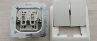
The only difference between a two-key device and a single-key device is the presence of a pair of output contacts. Each contact is connected to a phase conductor of one of the lamps.
Scheme with a two-key switch
Before connecting the wires into the circuit, you must have the following installed:
Two lamps for one bulb. For example, one in the kitchen, the second in the hallway. Distribution box under the ceiling (15-30 cm below the ceiling level). If the room already has a distribution box, you can use it. The main thing is that there is not a lot of switching and that it is convenient for you to work. Socket box for two-button switch. As a rule, it is installed at a distance of 90-100 cm from the floor level. Wires must be laid in grooves between all these elements
Please note that in the case of a two-key switch, a three-wire wire must be connected to it from the distribution box.
Now we need to connect all this electrically so that voltage comes from the power source to the light bulbs.
Two strands of wire from the supply network come into the distribution box - zero and phase. Using an indicator screwdriver, identify the phase conductor. Touch both wires one by one with a screwdriver. If you touch zero, the indicator window will not light up. If the window lights up, it means you have found a phase conductor. Carefully mark it with insulating tape.
Now to make connections, turn off the power to your workplace. You need to turn off the circuit breaker that supplies voltage. Nowadays, in many houses and apartments, entire panels are installed, in which there are circuit breakers that turn off each room. If you don’t have one yet, then you’ll have to turn off the water machine for your apartment. Check that there is no voltage and get to work.
Three strands of wire are inserted into the socket box. Strip off the insulating layer on them by 1 cm (this is done with a knife). Connect one core to the incoming contact of the switch, connect its second end in the distribution box to the phase wire of the power supply network. Connect the other two wires to the two output contacts of the switch. Accordingly, connect their second ends in a distribution box with phase conductors from one and the second lamp.
Now you can place the working part of the switch in the socket box, fix it, install the protective frame and keys.
There will be one more connection in the distribution box; connect the neutral conductors coming from the lamps to the neutral from the supply network.
The lamp sockets have two contacts - one side for connecting the neutral conductor, and a central one, the phase is connected to it. Make these connections.
Check that all contacts are reliable, but we advise you to insulate the twisted areas after you are sure that the switch is working correctly. To check the assembled circuit, apply voltage to the apartment (that is, turn on the input circuit breaker). Both keys of your switching device are in the off position, the lights in the kitchen and in the corridor are not lit. Press one key - the light in the kitchen comes on, turn on the second - light appears in the corridor. Also, turn off the first and second keys one by one, the lights went out first in the kitchen, then in the hallway. Everything works correctly.
Turn off the input circuit breaker again and insulate the places of twists in the distribution box with insulating tape; you can also put PVC tubes on top.
The circuit with a double switch is discussed in detail in this video:
Preparatory work: ringing - determining the phase on the ceiling
At this stage of preparation, it will be clarified what to do with the ground wire and how to distinguish between phase and zero on the ceiling? How to connect many threads of wires from a chandelier with cables on the ceiling? Connecting a lighting device with your own hands is a neat job, requiring minimal knowledge of electricity.
The indicator will help you find the right cable
Ground wire
If the wiring is already done on the ceiling (the wiring is done, say, under plasterboard in a frame base), then among them there is a “zero”, the rest are phase and ground.
Attention! Wiring with grounding is done in new buildings and in rooms with renovations.
Proper insulation
Looking for phases and zero
All wires are checked - you need to determine where the phase and zero are. You can't rely on color alone for several reasons. Firstly, it is not known (in many cases) how the wires were connected to the junction box - the qualifications of an electrician or a neighbor; secondly, the color range can change, and if a person is sure that the phase is red in color, then this opinion may be wrong.
If there are only three wires coming from the ceiling, a switch with 2 keys is installed, then there may be two supply wires for each section of the switch, and one zero - common. The call is made using a multimeter (tester) or indicator.
- Wear shoes with rubber soles. Be in a dry room. Hands and feet should also be dry. Water is a conductor of current.
- The voltage is turned on at the meter or panel, and the switch is set to “on” mode.
- Be careful that the wires do not touch each other (so as not to burn all the wiring in the house) with an indicator and the edge of a screwdriver, touch each one in turn. If the screwdriver lights up, there is voltage.
- When connecting a measuring device, the tester will show, with an arrow or numbers on the display, what voltage is in the wire.
- To be sure (if the memory is bad), the phase is outlined with a marker or everything is written down on paper - what color.
- After the phase is detected, the switch is turned off, and then the apartment is de-energized at the electrical panel or at the meter.
Expert opinion
Viktor Pavlovich Strebizh, lighting and electrical expert
Any questions ask me, I will help!
The phase, as a rule, is connected to a white or red wire, zero to blue or black, and yellow, green or yellow-green color is used for grounding. If there is something you don’t understand, write to me!
Connection diagram of a single-key switch to a light bulb
First of all, power must be supplied to the circuit breaker. After this, the connection diagram for the switch and light bulb is carried out in stages. The wires in the cable used are usually blue and black, as well as yellow with a green stripe on it. The blue wire is used for zero, the yellow wire is for grounding, and the black wire is for phase. The colors of the wires for all connections must be observed in a certain order. The stripped wires are inserted into the contact terminals and clamped with special screws. All other nodes are connected in the same way.
When connecting the lamp, preparation is also carried out with wire. In this case, grounding is not used, but only the neutral and phase wires are used. After preparation, the wires are connected directly to the socket and to the switch. After this, the diagram takes on a finished form.
To check the functionality of the circuit, you need to screw a light bulb into the socket. Voltage is supplied to the circuit breaker, after which it turns on. The correctness of all connections is first checked by an indicator. After pressing the switch button, the light should light up, which means that the entire circuit is completed correctly.
Connecting switches
There is only one way to connect two pass-through switches in order to switch two electrical devices, so you cannot make a mistake. But if you don’t know how to connect two switches to two light bulbs, it’s better to refer to the diagram - it has certain difficulties. Further in the article there is a diagram according to which you can connect one lamp.
This is a typical diagram, which shows that pass-through switches are connected in series to the power supply circuit break, and the pass-through switches are connected with one two-wire wire. If you look closely at the diagram, you can see that the power can be opened and closed at any position of the switches.
Useful tips Connection diagrams Principles of operation of devices Main concepts Meters from Energomer Precautions Incandescent lamps Video instructions for the master Testing with a multimeter
Difference between parallel and series connection of lamps
If any light bulbs are connected in parallel to each other and, accordingly, in series with the switch, then the voltage on each of them will be equal and in this way light sources of different powers can be connected. The main condition is that the operating voltage at which they operate normally must be equal to the voltage of the power source. If in this case a step-down device with a rectification system is used, then the opening contact must disconnect the circuit in front of the converter, as shown in the figure.
In this case, it does not matter whether two or three light sources will be turned on. Most often these are halogen and LED lamps, designed for a reduced voltage of 12 or 24 Volts.
With a serial connection the situation changes dramatically. The supply voltage will be divided by the number of light bulbs, that is, if the network is 220 Volts, then on two artificial light sources connected in a series circuit, the voltage will be approximately 110 Volts. This must be taken into account when choosing and purchasing them. Another nuance with this connection is related to the power of each of them. It should be the same or as close as possible to each other, because With such a connection, the current is the same in all parts of the circuit. If one lamp is 500 W and the other is 50 W, then the lamp with the lower power, connected by one wire to each other, will still flow more current, corresponding to the most powerful load. A light bulb with less power will burn out instantly. This rule applies to all types of lamp sources, from incandescent to LED.
If you need to connect an LED light source from the network or from sockets, it often consists of a so-called driver installed inside the light bulb housing. It performs several functions at once: rectifying and reducing. These lighting devices are not intended for serial connection, only for parallel connection.
For fluorescent daylight sources, both with an electronic starting device and a starter, a series connection is most often found in raster lamps, as it allows one choke and two starters to ensure stable operation. In this case, the starter itself is selected for 127 V with the calculation of the operating voltage of a standard 220 Volt network. The switch in this circuit uses a regular single-key switch and also breaks the phase wire with its contact.
As for the parallel connection of several fluorescent lamps or compact lamps, the operation of which is based on the glow of a phosphor applied to a glass tube, then in this situation it is possible to connect any number to one switch, either single-key or two-key. The main thing is to take into account the power of all light sources, on which the current in their circuit directly depends. For any switch it is limited and indicated in the technical data sheet, on the packaging or case. If, for example, a current of 5 A is specified, then you should not exceed its value, since this will very quickly render the breaking contact itself unusable.
To fully understand the serial and parallel connection of light bulbs, we recommend watching the video:
Connecting recessed ceiling lights with 12 V LED lamps
Spotlights can also operate from a reduced voltage of 12 V. Then LED bulbs are installed in them. They are connected in a parallel circuit, power is supplied from a transformer (voltage converter). It is placed after the switch, and voltage is supplied from its outputs to the lamps.
Connection diagram for 12 V spotlights via a common transformer
In this case, the power of the transformer is found as the total power of the load connected to it, with a margin of 20-30%. For example, you need to install 8 lighting points of 6 watts each (this is the power of LED bulbs). The total load is 48 W, we take a margin of 30% (so that the trans does not work at the limit of its capabilities and lasts longer). It turns out that you need to look for a voltage converter with a power of at least 62.4 W.
If you want to divide the light sources into several groups, you will need several transformers - one for each group. You will also need a multi-position switch (or several regular ones).
Connecting 12 V lamps via a double switch
Both of these schemes have one drawback - if the adapter fails, a group of lamps or even all of them do not work. If desired, you can connect 12-volt spotlights to increase the reliability of their operation. To do this, each light source is equipped with its own transformer.
Connecting 12 V spotlights with a personal transformer
From an operational point of view, the almost ideal connection diagram for 12-volt lamps is with a transformer for each lighting element.
Connection diagram for 12 V spotlights with a personal transformer
In this case, transformers are connected in parallel, and the lamps themselves are connected to their outputs. This method is more expensive. But when the transformer fails, only one lamp does not light up and there are no problems with identifying the damaged area.
Selection of wire cross-section
When a low voltage is supplied, the current flows to the lamps large and the losses along the length will be significant. Therefore, to connect 12 V spotlights, it is important to choose the correct cable cross-section. The easiest way to do this is according to the table, focusing on the length of the cable laid to each lamp and the current consumption.
Table for determining the cable cross-section when connecting 12 V spotlights
The current can be calculated by dividing the power by the voltage. For example, we connect four spotlights with 7 W LED lamps. Voltage - 12 V. Total power - 4 * 7 = 28 W. Current - 28 W/12 V = 2.3 A. In the table we take the nearest higher current value. In this case it is 4 A.
For a line length of up to 8.5 meters, you can use a copper cable with a cross-section of 0.75 mm 2 . Such a small cross-section is obtained solely due to the low power of LED lamps. When using housekeepers, halogen or incandescent lamps, the cross-section will be much larger, since the currents increase significantly.
This method of calculating the cable cross-section is suitable for a loop-type parallel connection with one transformer. With beam lighting, the same actions have to be performed for each lamp.
Installation features
Spotlights are usually mounted in suspended or tensioned streams. Another option is cabinet lighting. In any case, according to the PUE, the gasket is hidden, and it is recommended to use a cable in a non-flammable sheath.
The most popular option is to connect spotlights with a VVGng cable. If desired, you can choose an even safer version - VVGng Ls, which emits little smoke during a fire.
The use of cables or wires that do not contain the letter NG in the marking is at your own peril and risk. Because when the lighting operates, heat is generated, which can lead to a fire.
If spotlights are mounted in a suspended ceiling, the cable can be laid in transverse profiles to which plasterboard is not attached. It is not worth putting it in longitudinal ones, since there is a high chance of damaging the insulation with a self-tapping screw when installing plasterboard sheets. Another option is to attach the cables to the profiles from the side, tightening them with plastic ties.
You can lay the cable for connecting spotlights in transverse profiles that are located higher
In this case, first assemble the frame, then stretch the wires, leaving the ends 20-30 cm for ease of installation. When using 12 V lamps, transformers are located in close proximity to one of the holes. If damaged or maintenance is required, you can reach it by pulling out the lamp.
If a suspended ceiling is planned, the cables are attached first of all directly to the ceiling. In this case, they are often placed in a corrugated hose to increase fire safety. You can use any suitable cable fasteners - cable ties, dowel ties, clips of a suitable size, wire trays, etc.
When wiring is already present in an apartment or house and there is no need to connect additional light sources, then the question of how to connect a lamp is not relevant. But how can this work be done when the need arises? Here you can’t do without basic knowledge of electrical engineering and the ability to draw up a fundamental, seemingly elementary diagram.
All fluorescent light sources (housekeepers), incandescent lamps, LED lamps can be connected, as in principle all resistances present in the electrical circuit, in parallel, in series, mixed. A mixed connection is not used to connect lamps, since it is simply not necessary. But it’s worth paying attention to parallel and serial connections in more detail.
Read also: How to connect a motion sensor instead of a switch
Safety regulations
To ensure that no unforeseen situations arise during the installation of a two-key switch, you must try to follow basic safety precautions. They will help avoid any injuries and reduce the likelihood of device failure.
Basic safety rules:
- Any work with electricity should only be carried out by people with sufficient knowledge and experience. Otherwise, the likelihood of any injury will increase significantly.
- Measures to install the switch can only be carried out after turning off the power supply to the room. At the same time, care should be taken to ensure that no one accidentally turns on the electricity.
- Before touching exposed wires, you need to check them with a special indicator screwdriver for the presence of voltage.
- It is forbidden to touch two bare wires with your hands, even if they are disconnected from the power supply.
- Do not touch the wires with wet hands. The same applies to other structural elements capable of conducting electric current.
- Any preventive, installation or repair measures can only be carried out using tools equipped with insulated handles.
- Experts recommend carefully isolating all potentially dangerous places. This simple action will help avoid accidental contact of contacts, which will cause a short circuit.
- It is prohibited to turn on the power supply in the room until the installation work is completed.
- Clothing and shoes should not create discomfort or distract the technician from the installation process.
- When testing an installed switch, you should be extremely careful and remember the safety rules.
Thus, almost anyone can install a two-key switch. And provided you follow the advice of professionals and safety regulations, everything will go quickly and smoothly.
Parallel connection
The most common and convenient scheme is parallel. It requires more wiring, but all spots are supplied with the same voltage and the lighting is equally bright. If one lamp fails, the rest remain on. Finding the location of the breakdown is very easy.
To prevent overheating, as well as short circuits, it is recommended to lay a non-flammable wire VVG ng 2*1.5 - two-wire, or 3*1.5 - three-wire, if there is grounding. Ways to connect lamps in parallel - loop and beam.
Two lamps per switch
Connection diagram for several light bulbs to a switch:
- De-energize the system. We connect the stripped wires to the contacts carefully, in accordance with the principles outlined above.
- The junction box receives zero and phase from the general network. The zero coming from there must pass through all the lamps. We bring it directly to the lamps, bypassing the switch.
- The phase passed through the switch is sent to the central contacts of the bases. It comes from the network into the distribution box and passes through the input on the switch.
- The phase is then output through the outgoing contacts on the device.
- From there we send the phase to go through two lamps. We remove it from the switch through two separate cables.
When constructing a circuit, it is necessary to calculate the total power of the light bulbs. Each of them must be marked indicating the maximum load limit.
To securely fasten the contacts, you need to use screw or spring type terminal clamps.
You should not try to connect different types of metal together. Copper and aluminum, once twisted, will begin to oxidize. As a result, the contact will overheat and become loose.
Connecting one lamp to a single-key model
Let us describe a method for connecting a light bulb to a switch with one control button. Some types of symbols indicated on the device:
- if number 1 is marked, this is an input phase contact, number three is marked as an outgoing phase contact;
- letter designation L – incoming phase contact, number 1 – outgoing phase;
- L – input, arrow – exit.
Important! The phase cable is often marked in red, and the neutral cable in blue.
The following tools will be useful during the work process:
- knife to scrape insulation from wires;
- screwdrivers with insulated handles: indicator and Phillips;
- marker;
- insulating tape.
Instructions:
- Turn off the electricity at the machine or panel.
- The switch is mounted where the phase break was provided. The “zero” wire goes to the light bulb.
- Strip the insulation from the wires. The ends should be trimmed 8-10 mm on each side.
- We connect the phase to the input contact of the switch. With the standard location of the switch, the input terminal should be located at the bottom.
- We conduct the phase from the lighting fixtures to the outgoing contact terminals.
- Press the wire to the contact, tighten the screws. The core should move 1-2 mm away from the contact.
- The phase from the distribution box is connected to the phase contact of the switch.
- We run wires from the switch to the lamp. We take the zero directly from the switchboard to the rim of the base. The phase passes through the switch and is connected to the central contact of the light bulb.
- Insulation of twisted wires.
- Starting the machine.
- Checking the system's functionality.
Under no circumstances should the switch be connected to zero. The load on the device will increase too much. This will lead to rapid burnout of contacts.
By installing the switch on a phase, the supply of current to the end user can be quickly interrupted. This is relevant in case of emergencies. Setting the switch to “zero” will not give the desired result in emergency conditions. Disabling in this case will only open the circuit, but will not lead to de-energization of the entire system.
Important! Any work with electricity must be carried out only with the system completely de-energized. Current can be sent to the network only to determine the phase and purpose of other wires. Before you do this, you need to make sure that there are no electrical shorts on the line. To do this, make sure that the cable insulation is not damaged.
Switch device
The working part of the switch is a thin metal frame with a drive installed on it. The frame is mounted in a socket box. A drive is an electrical contact, that is, a device on which electrically conductive wires are connected. The drive on the switch is movable, and its position determines whether the circuit is closed or open. When the circuit is closed, the electricity is on. An open circuit makes it impossible to transmit current.
The drive provides electricity or an obstacle to the path of the signal transmitted between two fixed contacts:
- the input contact goes to the phase from the electrical wiring;
- the outgoing contact is connected to the phase going to the lamp.
The normal contact position on the actuator implies that the commutator is off. The fixed contacts are open at this time and there is no lighting.
Pressing the control button on the switch completes the circuit. The moving contact changes its position, and the fixed parts become connected to each other. Along this path, the voltage network transmits electricity to the light bulb.
To ensure the safety of the system, the working part must be placed in a housing made of materials that are not capable of conducting electric current. In the switch such materials can be:
Other design elements directly protect the user:
- The control key allows you to change the state of the circuit with one touch, closing and opening it at the request of the person. As a result of a light press, the light in the room turns on or off.
- The frame completely insulates the contact part, which eliminates accidental touches and electric shocks. It is attached with special screws, and then sits on hidden latches.
Plastic is effectively used as the main material for their manufacture.
What are pass-through switches used for?
The second option is a long corridor devoid of natural light. The light turns on at the beginning and turns off at the end, or vice versa. Comfortable? Undoubtedly. So before you connect two switches to two light bulbs, you should think carefully about whether to replace this circuit with a version with pass-through switches.
Externally, pass-through switches are almost no different from ordinary ones. Only on the reverse side there are three terminals instead of two:
How to connect a lamp to two switches correctly is shown in the diagram.
In staircases, long corridors or tunnels, instead of expensive infrared sensors, you can simply connect two pass-through switches.
Safety conditions
Installation of pass-through switches is possible with both open and hidden wiring systems.
Installation can be carried out independently, only if you follow the necessary safety rules:
- Before starting installation work, it is necessary to turn off the power to the apartment.
- It is necessary to correctly determine the location of the phase and zero.
- The wires should be connected by neat twisting, while crimping and insulating them.
- It is recommended to firmly fix electrical accessories and branch boxes to surfaces.
- Based on the power of electricity consumed, you need to determine the power parameter of the lighting device and select a three-core cable of the required cross-section.
Due to a design feature, the keys of backup electrical switches do not have a specific “on” or “off” position. Based on the position of the electrical contacts of the other switch, the two connecting nodes of this system correspond to the “closed” or “open” position. Therefore, when the light is turned off, the key will be in a different position each time. This feature is not a problem - you can quickly get used to it.
What is a pass-through switch?
What are these devices and where are they used? In addition to the considered option of how to connect two switches to two light bulbs, there is a better option: using two switches located at different points, control one lighting fixture.
The design of standard household switches is usually the same. There are two contacts - a fixed one, mounted on the device body and a movable one, mounted on the rocker arm. The rocker changes its position under the action of the key. The device accordingly has two positions “On” and “Off”.
The pass-through switch (it would be more correct to call it a “switch”) does not have an “Off” position. As can be seen from the figure, it has the following provisions:
Expert opinion
Viktor Pavlovich Strebizh, lighting and electrical expert
Any questions ask me, I will help!
To correctly connect other types of lighting devices, you must first know their operating principle and familiarize yourself with the connection diagram. If there is something you don’t understand, write to me!
Types of lamps for home use
Tube progress keeps pace with switches. Their diversity is also impressive.
But here, too, some more popular types are defined:
- Incandescent light bulbs are established home light sources in a round glass bulb with a vacuum and a tungsten filament inside.
- Halogen lamps are the same incandescent lamps filled with a special gas. It increases service life and minimizes the size of their flasks. Disadvantage: When installing, you cannot touch the glass of the flask with your hands.
- Fluorescent fluorescent lamps are not very common at home, but they are also traditional lighting devices (hereinafter simply “fluorescent lamps”).
- Energy-saving LED lamps, as the name suggests, use the glow of groups of LEDs. They can be fixed into ordinary screw-in sockets (hereinafter simply “LED lamps”).
Energy-saving fluorescent light bulbs are increasingly replacing the usual ones. The operating principle is similar to fluorescent lamps. They are screwed in like incandescent lamps (hereinafter simply “energy-saving lamps”).
Regular switch for one lamp
Diagram for connecting a lamp to a regular switch
You should start with the simplest option, and therefore it makes sense to start with the basics. When installing the switch, you need to remember that it is placed on the break of the phase wire, therefore, the zero will go directly to the light source. When the switch is set to zero, the contacts of the device can quickly burn out. Surely many have noticed that when there is poor contact in the socket, the zero most often burns out. This happens due to the greater load when current passes at the zero contact.
Another reason for the breaker to break the phase wire is the ability to quickly remove voltage from the consumer in the event of an emergency situation, while a zero break will not provide de-energization, but will only disconnect the circuit.
The main rule is that work on installing electrical wiring, switches and lamps is carried out strictly with the voltage completely removed. If it is impossible to determine the phase wire by color, a short-term supply of electricity is allowed for the purpose of “ringing”. In this case, you must first make sure that there are no short circuits in the exposed wires.
A few words about electric current
Without “loading” with theory and complex physical concepts, let us recall the elementary basics of electrics. The household electrical network has a voltage of 220 V, the type of current is alternating. What does it mean? One of the contacts, “phase,” has a constantly changing potential from “+” to “−” (50 cycles per second), and the other “zero” serves as a kind of battery, allowing electrons to either accumulate in excess or flow back.
Each lamp has two contacts: base and central. In order for our lighting device to start working, zero and phase must be connected to these two contacts. Moreover, in the case of alternating current and a regular household lamp, polarity does not play any role.
But it is still necessary to know the location of “zero” and “phase”. There is a special device - a “probe”, which is used to determine which of the wires is phase. This must be kept in mind for the correct inclusion of a disconnecting device - a switch - in the circuit. It must necessarily break the “phase”, these are the safety requirements.
Connection from an outlet
In some cases, you need to connect an additional lighting fixture with a dedicated switch. In this situation, connecting from an existing outlet will do.
When installing a single-key switch, you will need a two-wire wire and a switching device. For a voltage breaker installed above the socket, zero and phase are removed from it. The phase wire is interrupted inside the switch, and the neutral wire is left intact. Other lighting devices in the circuit are provided with power in a similar way to the above circuits.
For electrical installation work, you will need three wires (zero and two phases). For a three-key switch, one more phase core is required.