Currently, all electronic devices contain a complex design consisting of many components. From time to time there is a need to repair such devices.
Repair usually consists of replacing faulty parts with new ones. And if earlier it was possible to simply use a soldering iron for this, then with the advent of components in BGA packages, even the use of hot-air soldering is not always successful.
Experts use an IR soldering iron or soldering station that emits infrared waves.
Description of the IR soldering process
The challenge when working with BGA components is the need to heat and melt large numbers of solder balls at once.
When they are heated, some heat is transferred to the circuit board due to the thermal conductivity of the materials. The heat provided by the soldering station is no longer enough.
Increasing the heating time or increasing the temperature does not have the best effect on the microcircuit. It may overheat and fail.
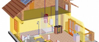
The solution suggests itself - you need to preheat the circuit board from below, without exposing the chip to heat. It can be heated either by air flow or by calm infrared radiation.
As a result, as the temperature of the board material rises, the heat dissipation from the pin legs will decrease and it will take less temperature and less exposure time to melt the solder balls.
When using infrared soldering, special devices are used for bottom heating - heat tables. This is the operating principle of an infrared soldering station.
Infrared soldering has many advantages over hot air soldering. If with hot-air soldering it is possible to control only the speed of air flow from the nozzle and the temperature of the heating element, and it is completely impossible to control the outflow of air, then with infrared soldering the temperature of the solder can be controlled throughout the entire work cycle.
The use of an infrared soldering station allows for more precise impact on a specific area of the board, which is difficult when soldering with hot air.
And during repair work, the task is precisely to replace one or more components of the circuit without affecting others at all.
Purpose and objectives of application
Soldering stations are used in radio engineering and related areas of production and creativity. Users use the tool to perform different types of work.
- Pyrography is the making of drawings using thermal devices. By heating individual sections of the workpieces, the position of the thermoplastic elements is changed. Compositions are created from plastics of one color or multi-color compositions.
- Weld plastics in the manufacture of cases, boxes or other flat and spatial products.
- Carrying out installation, repairs and other targeted work. Some types of work are only possible with the use of hair dryers that melt plastic particles without overheating it.
- For assembling electronic devices and instruments.
- Soldering and installation of electronic circuits in electronics.
- Tinning and preparation for complex installation of massive parts and assemblies connected by melting solder.
- For welding in confined spaces.
- Soldering SMD components, mounting and dismantling them on boards.
- For shrinking heat-shrinkable insulation upon completion of work.
Model IK-650 PRO
One of the most common professional-level infrared soldering stations is the IK-650 PRO. In Russia, this device was one of the first capable of successfully repairing equipment with BGA circuits.
The soldering is done so well that a strong opinion has arisen about the absolute reliability of devices whose boards were mounted using this infrared soldering station.
The software allows you to very accurately maintain the temperature profile, which is important for creating strong, reliable contacts. After all, for high-quality soldering it is necessary not only to create a temperature sufficient to melt the solder, but also to raise it smoothly and then smoothly lower it, avoiding a sharp cooling of the contact.
Only then will a strong crystal lattice be created in a drop of solder connecting the contact of the microcircuit with the mounting patch.
The infrared station has a modular design and allows you to assemble many possible configurations for preliminary and auxiliary work:
- it is possible to use various types of thermal tables;
- connecting an electron microscope;
- automatic control of heating and cooling temperatures;
- There are additional modules for restoring BGA pins (this is called reballing).
The soldering station also includes vacuum tweezers, which are convenient for installing small parts on the board.
The cost of the infrared soldering station IK-650 PRO is currently more than 150,000 rubles. It is professional equipment and, of course, is practically inaccessible for amateur use.
DIY digital soldering station
In this post we will be making an inexpensive Hakko 907 digital soldering station at home! It is capable of maintaining variable and constant temperatures (up to 525 °C). To create a soldering station you will need several components totaling only $7 (not including the power supply, but you can use an existing power supply). I couldn't find detailed instructions on how to create such a station, so I decided to prepare my own tutorial detailing the process.
Specifications
- The station is designed for Hakko 907 hand soldering irons.
- The station is compatible with hand-held soldering irons of the same type.
- Temperature range: 27 to 525 °C.
- Warm-up time: from 25 to 37 s (up to 325 °C).
- Recommended power supply: 24 V, 3 A.
- Power: 50 W (average).
Full video instructions
Assembly diagram, PCB layout, code and files of the standard template library are available here.
Step 1. Conventional and digital soldering irons
Like any DIYer, I took a regular soldering iron as a basis. These soldering irons work great, but they have a number of disadvantages. Any home craftsman who has soldered at least once knows that heating such soldering irons takes from 7 to 15 minutes and only after that they can be used for their intended purpose. After heating, such soldering irons continue to operate in the maximum temperature range. In some cases, such soldering irons may damage them if they come into contact with electronic components for a long time. I know from my own experience that if you fail to touch a perforated breadboard with a very hot soldering iron tip, you can damage the copper layer glued to the board. Generally speaking, such mistakes can be avoided, and there are ways and techniques for this, but once you try soldering with a digital soldering station, you will never have the desire to return to the old methods.
Conventional soldering irons with temperature controller
To regulate the heating temperature of conventional soldering irons, there is a simple and common way - to connect a temperature regulator to the power circuit, which limits the power supplied to the heating element. Such regulators are installed on products quite often. At one time I had a Weller soldering station with such a regulator. And it was actually very convenient! The only drawback of this method is the absence of a closed temperature feedback loop. In some cases, the temperature of the soldering iron will be lower than that set by the regulator, since as heat-absorbing components are soldered, the temperature of the tip will decrease. To compensate for the drop in temperature, you can turn the knob, but as soon as you stop soldering, the temperature will rise again. The heating time of the soldering iron can be reduced somewhat if you turn the regulator to the extreme (maximum) position, and after heating, turn it back.
Digital soldering station
I prefer the third method - my favorite. It is quite similar to using a soldering iron with a temperature controller, but everything is done automatically using a PID (Proportional Integral Derivative) system. In simple terms, such an automated electronic soldering station control system “turns” the temperature control knob for you. If the system detects that the soldering iron tip temperature drops below the set value, the system will increase the power to the value required to generate heat at the soldering iron tip. If the temperature of the soldering iron rises above the set value, power will stop being supplied to the soldering iron, causing the temperature to drop. With the help of such a system, the entire soldering process is accelerated - the system constantly turns on and off the heating element of the soldering iron and, thus, maintains a constant temperature at its tip. Therefore, when using digital soldering stations, the soldering iron heats up much faster.
Step 2: Components and Materials
Depending on where you are going to buy the station components, the final price of the system may be different (I advise you to purchase components on Aliexpress, it will be the cheapest). I’ll also try to find out which online stores can buy the cheapest components, and perhaps I’ll make some changes to the links. I purchased my components from a local store, E-Gizmo Mechatronics Manila. Materials required:
- Soldering iron Hakko 907 (similar for $3).
- Arduino Nano programmable controller.
- Buck converter (MP2303 made by D-SUN).
- Female 5-pin DIN connector.
- Jack for connecting an external DC power source (2.1 mm).
- Power supply 24 V, 3 A.
- LCD 16X2 I2C.
- Operational amplifier LM358.
- MOSFET transistor IRLZ44N (I used IRLB4132, it is better).
- Electrolytic capacitor 470 µF, 25 V.
- Resistance 470 Ohm, 1/4 W.
- Resistance 2.7 kOhm, 1/4 W.
- Resistance 3.3 kOhm, 1/4 W.
- Resistance 10 kOhm 1/4 W.
- Potentiometer 10 kOhm.
NOTE: The IRFZ44N transistor is incorrectly indicated on the circuit diagram and printed circuit board. The IRLZ44N transistor should be used, this is the logic level version of the IRFZ44N transistor. In my system I used the IRLB4132 transistor, since it is easier to buy from us. Other MOSFETs can also be used. They will work normally if their specifications comply with those given below. In the old version of the soldering station I used an IRLZ44N transistor.
Recommended technical characteristics of MOSFETs:
- N-Channel Logic Level MOSFET – Logic level MOSFETs can be directly connected to the logic board pin connector (Arduino digital pin). Because the gate saturation voltage is lower than the typical Vgs voltages of standard MOSFETs, a gate is provided on the logic level MOSFET to supply saturation voltages of 5 or 3.3 V (Vgs). Some manufacturers do not indicate this in the technical specifications. This is reflected in the Vgs versus Id curve.
- The Vds value must be at least 30 V - this is the maximum voltage value of the MOSFET. We are working at 24 V, and, in principle, a Vgs value of 24 V should be enough, but usually some margin is added to ensure stable operation. The standard Vgs value for most MOSFETs is 30 V. MOSFETs with higher Vgs voltages are acceptable, but only if other specifications are within the range.
- Resistance Rds(on) 0.022 Ohm (22 mOhm): the lower the better. Rds(on) is the resistance formed at the drain and source terminals of the MOSFET in the saturated state. Simply put, the lower the Rds(on) values, the cooler the MOSFET will be. As Rds(on) increases, the MOSFET will heat up during operation due to power dissipation due to the small but still present resistivity of the MOSFET, even if it is conducting.
- Id at least 3A (I suggest more than 20A) is the maximum current the MOSFET can handle.
Step 3. Design
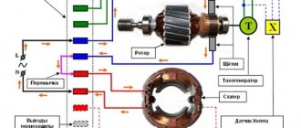
Inside the Hakko 907 soldering iron there is a heating element, next to which a temperature sensor is located. Both of these elements have a ceramic coating. The heating element is a regular coil that generates heat when power is applied. The temperature sensor is actually a thermistor. A thermistor behaves similarly to a resistor - as the temperature changes, the resistance of the thermistor changes.
Mysterious Hakko thermistor
Unfortunately, Hakko provides virtually no data on the thermistor installed inside the heating elements. This remained a mystery to me for many years. Back in 2022, I did some lab research trying to figure out the thermal characteristics of a mysterious thermistor. I attached a temperature probe to the soldering iron tip, connected an ohmmeter to the thermistor pins, and applied power to the heating element from the test bench. By increasing the temperature of the soldering iron, I recorded the corresponding resistance of the thermistor. As a result, I came up with a graph that turned out to be useful in designing the electrical circuit. Then I found out that perhaps this thermistor is a PTC thermistor. In other words, as the temperature near the thermistor increases, the resistance of the thermistor also increases. (I recommend referring to the third figure when performing the following steps.)
Voltage divider for sensor
Used to obtain useful output from a thermistor temperature sensor. I had to connect it using a voltage divider. It's the same story here - there are no technical specifications for this mystery sensor, so I installed a top resistor on the voltage divider to limit the maximum power dissipated at the sensor (I set the maximum value to 50 mW). Now that the top resistor appears on the voltage divider, I calculated the maximum output voltage at maximum operating temperature. The voltage at the output of the voltage divider was approximately 1.6 V. I then tried to solve the ADC compatibility issue for the Arduino Nano 10-bit programmable controller and ended up finding that I could not connect the voltage divider sensor directly because the values were too small and they may not be sufficient to obtain the desired result. To put it simply, if I connect the voltage divider sensor directly to the analog pin, there may be gaps between the temperature values (eg 325°C, 326°C, 328°C…..missing 327°C).
Operational amplifier
To overcome the potential problem of missing temperature values, I used an op-amp that amplified the low peak voltage output of the voltage divider (1.6V). The calculations presented in the third figure establish the required minimum gain value and the gain value I selected for the working system. I didn't adjust the gain to a value where the 1.6V output of the voltage divider would turn into a 5V ADC reference voltage in the Arduino, as I wanted to provide some headroom if other Hakko soldering irons connected to the voltage divider were producing voltages higher than 1.6 V (which can lead to non-linear distortion). A sufficiently large margin is provided when using a gain of 2.22, and the system will be able to work with other models of soldering irons.
Step 4. Circuit diagram
The project uses a simple N-channel logic-level MOS transistor as a switching device for voltage regulation using the pulse-width modulation method. It acts as a digital switch that supplies power to the heating element. A non-reversing operational amplifier (LM358) is used to amplify the very small voltages produced by the voltage divider thermistor. The temperature control is a 10k ohm potentiometer and the LED indicator is a regular indicator that I wired up and programmed to indicate the activity status of the heating element. In this project, I used a 16X2 LCD with an I2C interface bus driver, as it is easier for electronics beginners to understand.
Step 5: PCB
I laid out the PCB in the Proteus program. The board is intentionally laid out as one-sided so that no one has any difficulties in the process of assembling the system at home. Please note that if all elements are installed on the same side of the PCB, one jumper will be required. PDF files can be downloaded from Google Drive using the link below. Gerber files, if required, can be downloaded from Google Drive using the link below. You can also get my board design directly from the pcbway website, so you don't have to manually enter the Gerber files.
Step 6: Calibrate the Buck Converter.
Since most clones of the Arduino Nano programmable controller are capable of accepting an input voltage of no more than 15 V (higher voltage can damage the AMS1117 five-volt regulator), and the heating element requires a voltage of 24 V for optimal operation, I introduced a step-down voltage into the circuit for both of these components to work together. converter. The AMS1117 5V regulator present in most Arduino Nano programmable controller clones has a voltage dropout of 1.5V, in other words, the input voltage at the VIN pin of the Arduino Nano should be 6.5V (5V + 1.5V).
Steps:
- Set the voltage on the power supply to 24 V.
- Connect the power supply to the input of the buck converter.
- Using a multimeter, monitor the voltage at the output of the buck converter.
- Adjust the trim resistor to an output voltage of 6.5 V.
- For higher stability, the value can be set to 7 V.
Step 7: Assembling the system
To assemble the system, use a schematic diagram or component layout (see previous steps).
Step 8: 3D Printing the Case
Which case to choose - a cheap plastic one or mine designed for 3D printing - decide for yourself. I am attaching the corresponding Solidworks file for editing. If you need to print in advance, you can use STL files, which can be downloaded from the Google Drive link below.
My 3D printer settings:
- Printing is carried out on a Creality CR-10 printer.
- Level height 0.3 mm.
- Nozzle 0.5 mm.
- Filling 30%.
- No support.
Files for 3D printing (Solidworks and STL): Step 9. Finishing the body (painting and sanding).
Once printing is complete, the resulting 3D housing can be sanded. I painted my body black to make it look more elegant. Step 10: Install external components.
Secure the LCD display, 10 kOhm potentiometer, external DC power jack, and board into place in the case. Use superglue to attach the DIN connector and LCD to the case.
Step 11. Hakko 907 connector.
You, like me, may have a problem with the 5-pin DIN connector for your Hakko soldering iron. The pin connector can be cut out of the soldering iron and replaced with a 4-pin connector (you may have one). I found a pair of 5-pin DIN connectors, but not the one used on the Hakko. The third pin is a regular ground pin, you can ignore it if you don't want to bother with the grounding circuit and ESD protection.
Step 12: Connecting External Components
This connection can be made according to the circuit diagram (see previous steps). For added protection, I recommend adding a fuse in the circuit from the external DC jack to the board. I did not install a fuse, since my power supply already has a fuse.
Step 13: Programming
STEPS:
- Connect the Arduino programmable controller to your computer.
- Download my program template.
- Make any necessary changes to the template.
- For Hakko 907 soldering irons I used standard values.
- These values may need to be changed after calibration.
- Don't forget to install the Wire.h and LiquidCrystal_I2C.h libraries.
- Tools > Boards > Arduino Nano.
- Tools > Port > select the port to which the Arduino controller is connected.
- Download template/program.
How the code works
If the system detects that the soldering iron tip temperature drops below the set value, the system will increase the power to the value required to generate heat at the soldering iron tip. If the temperature of the soldering iron rises above the set value, power will stop being supplied to the soldering iron, causing the temperature to drop. With the help of such a system, the entire soldering process is accelerated - the system constantly turns on and off the heating element of the soldering iron and, thus, maintains a constant temperature at its tip. Therefore, when using digital soldering stations, the soldering iron heats up much faster.
PID control
The code does not use the PID technique. In the first version I used the old PID code and it works almost the same as the comparator version of the code (in this tutorial). I settled on a simpler version, since it is easier to work with (customize, modify, etc.). I can email the PID version, but it won't change much. Arduino Code (V1.0)
Step 14: Adjust the LCD contrast and insert the potentiometer knob.
If you have not used an Arduino controller and a 16x2 LCD display before, the first step is to adjust the LCD contrast trimmer. Once the setting is complete, the plastic knob for the temperature control potentiometer is inserted.
Step 15: Close the case and turn on the device
Now you can attach the back panel of the case. But before that, you need to check that the soldering station is calibrated correctly. The power source can be rechargeable batteries or any power supply with a rectifier from my list of power supply recommendations. To obtain maximum performance from a soldering station, I recommend using a 24 V, 3 A power supply. This soldering station power supply can be a switching power supply in a metal case or, alternatively, a laptop charger. If you don't want to buy a new power supply, you can purchase a used one. Laptop chargers are typically rated at 18V, 2.5A. They work fine, but the soldering iron can take up to 37 seconds to warm up. Step 16: Bonus: How to Increase Heat Transfer.
Tip: To ensure better heat transfer, I usually apply thermal paste to the tip of my Hakko 907 soldering iron. This technique works well and significantly improves heat transfer! During the first 30 minutes of work, do not forget to blow air onto the tip, as the paste may boil and begin to release fumes. After 30 minutes the paste will turn into a chalky substance. Over time, when you need to replace the tip, be aware that the dried paste will stick to the tip and heating element. You can remove the chalky substance using a rubber hammer.
Step 17. The station is ready for use!
I have been using this station for almost 5 years, and in this article I talked about how to make a modified version of it. I've made small improvements to the design so that anyone who is interested can do the same. I wonder if you will be able to assemble such a Hakko station?
Find out how to improve in other specialties or master them from scratch:
- Profession Data Scientist
- Profession Data Analyst
- Data Engineering Course
Other professions and courses
PROFESSIONS
- Profession Fullstack Python developer
- Profession Java developer
- Profession QA engineer in JAVA
- Profession Frontend developer
- Profession Ethical hacker
- Profession C++ developer
- Profession Game developer on Unity
- Profession Web developer
- Profession iOS developer from scratch
- Profession Android developer from scratch
COURSES
- Machine Learning Course
- Course "Machine Learning and Deep Learning"
- Course "Mathematics for Data Science"
- Course "Mathematics and Machine Learning for Data Science"
- Course "Python for Web Development"
- Course "Algorithms and Data Structures"
- Data Analytics Course
- DevOps course
Parts for a homemade device
Commercially available infrared soldering stations of domestic and foreign production are very widely available on sale, but their prices start from 20,000 rubles.
And at the minimum price, it will not be a tool of the best quality. If you need to work with BGA packages in conditions of limited funds, a homemade infrared soldering station can be a solution.
It can be assembled from parts of infrared stations available for sale, as well as from scrap materials and old devices that have expired.
A heat table for a soldering station can be made from a lamp or heater with halogen lamps, which will heat the board to the required temperature. The top heater and soldering station controller will have to be purchased from spare parts, buying them new or used.
A tripod for the upper heating block can be made from the support of an old table lamp.
For the heating table, you need to stock up on halogen lamps and reflectors. They are placed in a housing that can be made independently from aluminum profiles and sheet metal.
In addition to the lamps, it is necessary to provide a place in the housing for attaching a thermocouple, which will “supply” information about the temperature of the lamps to the control module.
The temperature must be maintained precisely so that the boards do not crack from excess heat and sudden temperature changes.
Why make a station yourself
There are several reasons why stations on the market are not trustworthy: you can never know for sure that you have purchased a good product until it goes through a full test drive; until you disassemble the station to see and evaluate the filling and build quality; and finally, you cannot communicate with other owners of the same model to share impressions and discuss the pros and cons of the station due to the fact that many companies release their products to the market under new brands every couple of years.
A couple of years ago I purchased a soldering station online, and although it still works well, I got tired of working with it due to the stupid design (short power cord, non-compressor airflow and short, non-detachable tip cord). Due to shortcomings in the design, it is inconvenient to rearrange this station even on the table; the body rotates after the sting. The inside was filled with hot glue; a week was spent just cleaning the components and eliminating minor and major defects.
The fastening of the cord of the soldering iron stand was kept on parole, the insulation was constantly knocked down, and this would lead to a break in the wire and a possible fire.
Assembly
An infrared head with a power of about 400-450 W must be mounted on a tripod using fasteners, the elements of which can be easily purchased in a retail chain; to control the temperature of the upper heating unit, a second thermocouple must be used.
It must be installed together with the heater. The cable can be laid in a flexible metal hose. The soldering station tripod must be mounted in such a way that the IR head can move freely over the entire surface.
It is necessary to provide brackets for fixing the board on the body of the thermal table. It should be located a few centimeters above halogen lamps. Suitable aluminum profiles can be used for the brackets.
The controller for the infrared soldering station is placed in a housing that can be made independently from sheet metal, preferably galvanized steel.
If necessary, you can build into the case the same cooling fans that are used in the computer case.
After assembling the structure itself, the entire circuit of the infrared soldering station will need to be debugged. This is done experimentally by repeatedly running the circuit and taking measurements. The process is not easy, but after setting it up it will give its results - the soldering station will work correctly.
General characteristics and operating principle
The circuit of a soldering station with a hair dryer includes a block and a manipulator-hot air gun, where the air is heated. The devices are used to repair cell phones and household appliances. The methods for generating air flow are as follows:
- Turbine - air is supplied by a small vane electric motor in a hot air gun.
- Compressor - air is supplied by a compressor located in the main unit.
Mainly, compressor stations differ from turbine stations in that the latter can generate a larger air flow, but do not push the air through narrow openings enough. Compressor stations are more efficient when air must pass through narrow nozzles used for soldering in hard-to-reach places.
The principle of operation of the station: the air flow passes through a spiral or ceramic heater in the tube of a thermal hair dryer, heats up to the required temperature and exits through special nozzles onto the workpiece. The hot air gun is capable of providing air temperatures of 100-800°C. In modern stations, temperature, power and air flow direction are easily regulated.
In comparison with other stations (in particular, infrared), the disadvantages of hot air stations are as follows:
- The air flow may blow away small parts.
- Uneven surface heating.
- Additional attachments required.
The advantage is that turbo air stations are much cheaper than others.
Contactless soldering iron
If there is no urgent need to use an infrared soldering station, then an infrared soldering iron can be successfully used for soldering. Outwardly, it is similar to a regular one, with the difference that instead of a sting it has a heating element.
Application and device
An infrared soldering iron is used in conditions where contact with component leads is unacceptable. It is also convenient to use it for soldering radio components, since often with a regular soldering iron carbon deposits form on the tip and the connections are of poor quality. The carbon deposits have to be cleaned off, and these actions sometimes take quite a lot of time.
In a home workshop, you can make a simple homemade infrared soldering iron from a car cigarette lighter. The heating element of this device is perfect for making tools.
Since normal operation of the cigarette lighter requires a direct current of 12 Volts, corresponding to the on-board electrical network of the car, you will need an electrical converter so that you can use a household AC network. For these purposes, you can successfully use a power supply for computer cases.
Purpose
To create a modern gadget or other product based on microcircuits, you need to make high-quality seams in a limited space. Soldering of some parts is carried out under significant amplification, even under a microscope. Only the presence of a soldering station makes it possible to achieve satisfactory performance characteristics.
Purchased stations necessarily include several main components:
- Control and control module. It helps the user navigate operating modes: current strength, voltage, tip temperature, air flow and a number of other indicators.
- A soldering iron capable of melting a specific type of solder. Overheating much higher than the specified values causes the formation of slag, which does not allow achieving acceptable quality.
- Tweezers with an internal heater can help in the installation and dismantling of microelements and SMD components.
- A hairdryer with a thermostat for warming up a local space and soldering groups of contacts (microcircuits) will help in difficult spaces.
- Infrared heat source for heating a large area on boards, as well as group installation.
- A directed heat emitter for spot heating of a space will help to perform miniature work.
- Devices for sucking out solder after desoldering parts.
- Auxiliary fittings, holders, special devices for spatial connection of parts. Antistatic devices for the master, as well as mats for placing parts and components.
In addition to the above, the stations are equipped with racks for placing tools with spring holders. Depending on the complexity and configuration, the installation price varies.
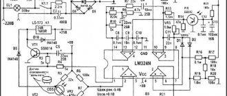
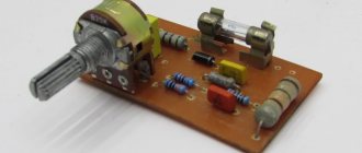
Schematic diagram
The scheme is extremely simple. At the heart of everything is the Atmega8 microcontroller. The signal from the optocoupler is fed to an operational amplifier with adjustable gain (for calibration) and then to the ADC input of the microcontroller. To display the temperature, a seven-segment indicator with a common cathode is used, the discharges of which are switched on through transistors. When rotating the BQ1 encoder knob, the temperature is set, and the rest of the time the current temperature is displayed. When turned on, the initial value is set to 280 degrees. Determining the difference between the current and required temperature, recalculating the coefficients of the PID components, the microcontroller heats up the soldering iron using PWM modulation. To power the logical part of the circuit, a simple 5V linear stabilizer DA1 is used.
Schematic diagram of Simple Solder MK936
Printing the body on a 3D printer (optional)
I designed and printed a case that could house a switching power supply and PCB to make everything look neat. Unfortunately, to use this case you will need to find the exact same type of power supply. If you have a suitable source and want to print the enclosure, or if you want to customize it to suit your requirements, you can download the attached files. I printed at 20% infill and 0.3 layer thickness. You can use higher infill levels and lower layer heights if you have the time and patience.
UPD
The files posted above are outdated. In the current version, we have updated the drawings for cutting plexiglass, making a printed circuit board, and also updated the firmware to remove the flickering indicator. Please note that the new firmware version requires CKSEL0, CKSEL2, CKSEL3, SUT0, BOOTSZ0, BOOTSZ1 and SPIEN to be enabled
(that is, change the default settings). Printed circuit board in Sprint Layout V1.1 format Firmware for microcontroller V1.1 File for cutting plexiglass V1.1
This soldering station can also be purchased as a kit for self-assembly in our store and from our partners GOOD-KITS.ru and ROBOTCLASS.ru.