Wire marking is a very important element in indicating the characteristics of electrical conductive materials, which is important for their correct and safe use. Today there are a large number of wires and cables that differ in both design and functional features. To determine these characteristics, appropriate color coding and alphabetic abbreviations are used, deciphering which can cause great difficulty even for experienced electricians.
Tables
All photos are clickable. Click to enlarge.
Marking of Russian cables:
- Power cables with PVC and rubber insulation.
- Control cables
- Cable with BPI - impregnated paper insulation
Domestic wires and cords:
- Explanation of markings and abbreviations of wires: KSPV, KPSVV, KPSVEV, PNSV, PV-1, PV-3, PVS, ShVVP, PUNP, PUGNP.
- Suspended wires: A, AC, SIP, Ng
- Power, installation wires and connecting cords.
- Installation wires
Marking of foreign cables:
- Power cable
- FROR Italian cables: Italian standard CEI UNEL 35011
- Control cable
- Halogen-free fire-resistant cable
- Cables with cross-linked polyethylene insulation
Foreign wires and cords:
Mounting wires:
Installation wires from foreign manufacturers
Brands and functions of some wires:
Well-known brands and applications of cables:
Areas of application for popular cords:
Laying methods
The VVG cable can be used in the construction of various objects, as well as in underground trenches. The laying method directly depends on the specific purpose. The conductor can be laid on various surfaces consisting of non-combustible materials. These include concrete, plaster, brick or plaster. The VVG cable can be laid openly under a variety of suspended structures.
A prerequisite is the exclusion of any mechanical influences. If there is a possibility of damage to the conductor, you need to think about additional protection. Often, special channels, tubes, metal or corrugated hoses are used for this.
Protective elements are also installed when the wire is laid on objects consisting of flammable materials.
The most popular is the hidden method. It is often used in residential premises when the cable is laid under plaster. First you need to make grooves in the walls , and then treat the product with cement plaster. In such situations, the possibility of mechanical impacts is eliminated, so there is no need to use additional protection. The only exception is when the wire is laid in wooden buildings. This option can be used in structures made of fireproof materials, for example, in pipes.
There is no wire that can be laid underground without the use of special protective elements. This is due to the fact that the cable needs to be preserved for a long period, but it itself is not equipped with built-in protection. Because of this, certain elements of protection against mechanical damage are used. In most cases they are sealed boxes.
You might be interested in this Characteristics of flexible metal hose for cable
general information
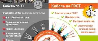
Cable marking makes it possible, when installing electrical networks, to find out such operating parameters of the conductor as core material, thickness, design voltage, functional purpose of the cable, material and flammable characteristics of the insulating sheath, and other features.
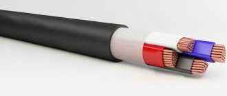
The designations “wire” and “cable” are, in principle, synonymous; the difference between them is determined only by the scope of application. Thus, wires are usually used to distribute electrical wiring under light load conditions, and cables are used to conduct electricity from power plants and in highly loaded networks; therefore, they are heavier, as they are equipped with good protection. There is also a category of “cords” - this is a flexible conductor with twisted conductors, used in the design of electrical appliances for mains power. Cords, as a rule, lack overall insulation.
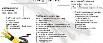
Despite the fact that the marking of wires and cables may have different letter designations in alphabetical order and case, it is always carried out in accordance with the general principle. First comes a description of the functional and design features using letters. For example, PUNP - wire (P) universal (UN) flat, and then digital markings of the number of cores and cross-sectional area of the conductors. Here the decoding of PUNP 3×1.5 means that this flat universal wire consists of three current-carrying wires with a cross-section of 1.5 mm2. The order of letters in the abbreviation depends on the strictly established GOST standard, and the thickness and number of cores must always come after them. After these data there is a designation of the climatic operating conditions (if there are any special features), and then the specifications or GOST according to which the cable products were manufactured.
According to the conditions under which and for what purposes conductors are used, they are divided into:
- power – used when laying electrical wiring;
- control - installed in the wiring that serves to transmit signals;
- control cables – installed in systems and circuits that control the operation of automatic systems;
- radio engineering – used in radio engineering installation.
Interpretation of cable markings according to CENELEC standards
Also in Europe there is the European Committee for Standardization CEN (CEN) and the European Committee for Standardization in the field of Electrical Engineering SENELEC (CENELEC). These committees develop uniform standards for the countries of the European Economic Union (EEC), including for cable products.
SENELEC issues the following documents:
- EN is the main European standard, mandatory after approval for use as a national standard for all member countries of the committee without any changes.
- HD - a harmonized document at the initial stage of development and subsequently subject to translation into EN;
Deciphering the markings
Deciphering the characteristics of a wire or cable begins with the symbolic marking applied by the manufacturer to the insulation - it usually contains comprehensive information about the materials from which the conductor is made and other parameters. The order of symbols and their meanings are established by GOST, with the exception of situations when conductors are made
So, the first letter in the marking of any cable indicates the metal of the cores, but it is not always placed. The fact is that only aluminum wires are marked with a capital letter “A”. And if there are copper conductors, no marking is applied.
The second (in copper wires - the first) letter in the marking allows you to find out the purpose of the cable. The following codes are used here:
- P – flat;
- M – installation;
- Ш or П(У) – installation;
- MG – installation cable with flexible cores;
- K – control.
The third letter in the marking of electrical conductors serves to designate the insulating material of the conductors. Their variety is quite large:
- V/VR – polyvinyl chloride shell;
- R – rubber is used to insulate the cores;
- N/NR – fire-resistant rubber or nayrite;
- K – nylon shell;
- L – varnished insulation;
- P – polyethylene;
- F – fold;
- E – enamel;
- Ш – polyamide type silk;
- O – polyamide silk insulation is braided;
- E – shielded insulation;
- G – insulating shell with flexible conductors;
- C – fiberglass;
- T – the insulation design includes a support cable.
The marking of a rubber insulated cable, which has additional protection made of nayrite or PVC, is done as follows: first indicate the above symbols, and then the marking of the cores.
The decoding of the following symbol makes it clear what design features this cable has. According to the current GOST, these are the following letters:
- A – asphalted cable;
- B – cable with armor tapes;
- G – flexible wire without protection;
- K – cable armored with round wire;
- T – wire intended for laying in pipes;
- A – the cable has additional braided protection.
The abbreviation frls at the end of the cable marking refers to the degree of compliance with fire safety requirements. FRLS is formed from two abbreviations that describe the characteristics of conductor materials: FR - fire resistance, LS - low smoke emission. Thanks to this, the frls cable does not support combustion even when laid in a group, and even remains operational for some time in fire conditions (this is important, for example, for the operation of a fire protection system). Most often, the frls version uses cables VVGng-FRLS (power), KPSEng(A)-FRLS, KSBNG(A)-FRLS (cables for fire protection systems).
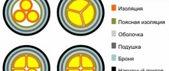
Table of colors used in cable markings:
White, natural or gray[/td]
| B | |
| Yellow | AND |
| Orange | ABOUT |
| Violet | F |
| Red | TO |
| Pink | R |
| Blue | WITH |
| Blue | G |
| Green | Z |
| Brown | Kch |
| Black | H |
| Green-yellow | Z-Z |
| Red-white | K-B |
| Brown-white | Kch-B |
Features of marking of individual cable types
The marking of power cables, as well as control cables and cables with PPI (impregnated paper insulation), may include separate symbols that indicate operational and design features.
For power cables (in accordance with GOST 16442-80):
- AA denotes a conductor with aluminum cores in an aluminum sheath;
- AC - similar to AA, only with a lead sheath;
- B – the cable is equipped with armor made of two tapes, which are coated with anti-corrosion material;
- B – the insulation of current-carrying conductors is made of polyvinyl chloride (it comes first in the marking of copper wires, for example, in the VVG cable);
- B – general insulating sheath made of polyvinyl chloride (ranks second in the marking of copper wires, like VVG);
- G – in this situation means “naked”, that is, the cable does not have a protective layer over the armor;
- ШВ – a cable in which the function of a protective layer is performed by an extruded polyvinyl chloride hose;
- ШП – cable with a protective layer of extruded polyethylene hose;
- K – cable with armor made of galvanized round wires (on top of them there is a protective layer);
- C – lead shell;
- O – a separate sheath is applied on top of each of the phase conductors;
- P – conductor with rubber insulation;
- P - sheath or insulation of cores made of polyethylene;
- PS - “S” means “self-extinguishing” - the polyethylene insulating shell does not support combustion and does not spread fire;
- PV – the insulation material is vulcanized polyethylene;
- NR - cable with flame retardant rubber insulation;
- NG - a cable with this designation does not support combustion (sometimes indicated in capital letters, for example, VVG ng);
- LS – stands for the English phrase low smoke, that is, a material with reduced smoke emission;
- NG-LS - insulation material emits little smoke and does not support combustion;
- FR – specific cables with fire-resistant insulation;
- FRLS - a modification that includes both high fire resistance and low smoke emission;
- E – the cable design includes a shielding layer of spiral copper wire;
- KG – flexible cable.
Common examples of cables with this marking are VVG, VVGng, VVG ng-LS, SIP, China, FOLS, VVGng-frls.
For cables with impregnated paper insulation (according to GOST 18410-73):
- The marking of aluminum wires begins with the symbol “A”; copper wires do not have any designation;
- B – equipped with armor made of steel flat strips (placed after the designation of the shell material);
- AB - armor made of aluminum;
- SB - lead armor;
- C – lead cable sheath;
- O - written to designate separately galvanized cores;
- P - steel armor wires have a flat shape;
- K – round-shaped steel wires in armor construction;
- B – if it appears after the dash at the end of the marking, it means BI with depleted impregnation;
- l – lavsan tape in the pillow design;
- 2l – double lavsan tape in the pillow design;
- d – “bare” cable without a protective layer;
- n - stands after the designation of armor and means that the outer layer does not burn;
- Shv and Shp - similar to the marking of power cables;
- (ozh) – single-wire conductors (placed at the end);
- U - stands at the end of cables with BPI and high heating temperature;
- C – the paper insulating layer of the cable is impregnated with a non-draining solution.
For control cables (in accordance with GOST 1508-78):
- the initial symbol, similar to previous standards, either means aluminum conductors (A) or is not written;
- B – the cores are insulated with polyvinyl chloride;
- B – general PVC sheath;
- P – polyethylene insulating shell (PS, if made of self-extinguishing material);
- G – naked;
- R – rubber insulation of cores;
- K – indicates the purpose (placed first for copper cables);
- KG – flexible;
- F – fluoroplastic insulation;
- E - in the middle of the marking indicates a shielded conductor, and at the beginning - for laying in mines.
Imported cables
The marking of cables from foreign companies naturally includes different symbols and their groups, the interpretation of which may depend on the purpose of a particular conductor.
For cables with XLPE insulation:
- N – is present in all wires in front of the abbreviation, means that the conductor meets the requirements of VDE (Union of German Electrical Engineers);
- Y – insulation of current-carrying conductors made of polyvinyl chloride;
- 2Y – polyethylene insulation;
- 2X – insulation is made of cross-linked polyethylene;
- S – the cable is equipped with copper wire shielding;
- (F) – conductor with longitudinal sealing;
- (FL) – with longitudinal and transverse sealing;
- E – three cores in the cable structure;
- R – steel armor made of round wire.
Halogen-free flame retardant:
- N – VDE compliance;
- NX – insulating layer made of cross-linked rubber;
- C – copper shielding;
- FE 180 – the cable maintains the integrity of the insulation during a fire for 3 hours (without installation with a fastening system);
- T 90 – maintains integrity for 1.5 hours when installed with a fastening system.
Power:
- N – corresponds to the standard of the Union of German Electrical Engineers;
- Y – polyvinyl chloride insulation;
- H – the plastic compound used for insulation contains no halogens;
- M – installation specialization of the conductor;
- C – the design has a copper screen;
- RG – presence of armor in the composition.
Mounting:
- H – wire made in accordance with HAR, harmonized;
- N – conforms to VDE standard;
- 05 – designed for operation under voltage 300/500 V;
- 07 – designed for operation under voltage 450/750 V;
- V – polyvinyl chloride insulation;
- K – the presence of a flexible core required for permanent installation.
Optical cables
It should be noted that the optical cable has a marking determined solely by its manufacturer, since no general standard has been adopted in this matter. This problem is typical only for Russian optical cable manufacturers, since European and American companies have already come to a single standard. FOCL (fiber optic communication lines) today are at the forefront of information transmission methods. FOCLs combine good transmission range, low losses, high protection against damage and electromagnetic fields. Due to the fact that fiber-optic lines are rapidly gaining popularity in our country, we can expect the speedy approval of standard optical cable markings in accordance with GOST. Today, when installing fiber-optic lines, the following conventional order of cable designation is used (according to the order of the symbols in the marking):
- Type of cable. Either OK (optical cable) or OKV (OK intra-facility).
- Shell material. N – flame retardant; G – upon contact with fire, does not emit halogens or smoke; T – made of tracking-resistant material.
- Armored cable cover. C – corrugated steel tape; A – high-strength aramid threads; O – steel wire braid; P – core strand made of fiberglass; B – braided wire made of galvanized steel (in 1 or 2 layers).
- External load-bearing element. /A – aramid; /P – fiberglass rod; /T – wire or cable made of steel.
- Numerical designation of the number of cables of the same type connected together (1,2,3...).
- Core design. T – central module; M – layering of modules.
- Number of elements in a layer or parallel modules (1,2,3...).
- The central strength element in the core. T – steel rope or wire coated with a polymer material; P – fiberglass rod with or without polymer coating.
- Number of optical fibers of one type (1,2,3...). Groups of different types are separated by a fraction.
- Optical fiber type. E, A, N, G – single-mode; M – multimode with a core diameter of 50 microns; B – multimode with a core diameter of 62.5 microns.
- Calculated tensile force (... kN).
To ensure the efficiency and safety of operation of fiber-optic lines, it is required that the marking of the optical conductor contain the year of manufacture, measurement marks and the trademark of the enterprise.
Cable type: twisted pair
Fire safety designation
In addition to other designations, special attention must be paid to fire safety markings, which is very important. Main parameters:
- The ng-frhf conductor can be used for group conduction - in the event of a fire, the fire will not spread. This is due to the fact that gaseous substances will not be formed during the combustion process.
- The designation ngfr-ls indicates a low spread of smoke and gaseous substances. This product can also be used in group settings.
- The ng-hf marking indicates that in the case of group wiring, no actively corrosive gaseous substances are formed in the event of a fire. In addition, such a conductor does not burn.
- The letters ng-LS indicate low levels of smoke and gas emissions. If the cable comes into contact with an open flame, combustion will not spread.
- Cable VVG-Png A - decoding indicates that the conductor is flat and is not subject to combustion even in an open fire.
You might be interested in this: Features of the use and installation of coaxial cable
If you are guided by this information, you can easily determine how popular conductors are deciphered. Some of them:
- VVG-Png is a flat, non-flammable cable, without armor, the outer and inner sheaths of which are made of polyvinyl chloride.
- VVGng A LS is a conductor, the inner and outer layers of which are made of PVC, non-flammable, low levels of smoke are emitted, the conductors are made of copper.
- For the VVG-Png A LS wire, the decoding is completely identical to the previous one, the only difference is that this type of cable is flat.
Brands of conductors and their purpose
Power cable VVG and its analogues
One of the most popular conductors today, used in installations for various purposes, is VVG. It is distinguished by a good combination of performance characteristics and an affordable price. In fact, the decoding of VVG sounds like “vinyl-vinyl-naked.” For the most part, VVG is produced with copper conductors, because cables with aluminum conductors are not recommended by the PUE. This is the most popular power cable in Russia and the CIS countries. There are also the following brands of cables for this purpose:
- AVVG with a number of cores from 1 to 4 and a cross section of each 2.5-50 mm2. The design includes aluminum conductors (the only difference from the standard VVG), sheath and PVC insulation. Used for open installation using sun protection channels.
- AVRG – from 1 to 4 cores with a cross-sectional area from 4-300 mm2 or 2.5-300 mm2. Power cable with aluminum core, rubber insulation and PVC sheath. Designed for laying over the air, overpasses, bridges and channels.
- ANRG. It has a similar design and core material, but differs in the presence of an oil-resistant sheath made of non-flammable rubber and rubber insulation. It is laid through channels, air, tunnels, bridges and overpasses.
- VVG - has 1-4 copper cores with a cross-sectional area of 1.5-50 mm2. It is laid outdoors along sun protection channels. It operates in a wide temperature range and is highly resistant to mechanical and atmospheric influences.
- VVGp is an analogue of VVG, differing only in the presence of flat conductors.
- VVGz - differs from VVG in that between the cores (insulated separately from each other) the space is filled with rubber material or plyvinyl chloride strands;
- VRG is a flexible cable with a copper core, PVC sheath and rubber insulation. It is used under the same conditions as VVG.
- NYM is a power cable that complies with foreign standards (VDE). Well protected from moisture and heat, but not resistant to sunlight.
- KG is a flexible cable with twisted copper conductors, which transmits alternating current up to 660V and 400 Hz. Most often used to power powerful electrical appliances.
- VBBShv – used to power stationary installations. It has good heat resistance and the ability to work at 98% humidity.
- AVBBSHv - analogue of the previous brand with aluminum conductors;
- VBBShvng - does not spread fire and does not ignite;
- VBBShvng-LS is an analogue of VBBShVng, the materials of which do not emit smoke and harmful substances when heated.
SIP cable
SIP stands for “self-supporting insulated wire”. It is recommended for use as a power conductor in overhead power lines (OHL). There are several brands of SIP with different performance characteristics; to distinguish them, they put a digital designation at the end of the marking:
- SIP -1 or -2 is designed for use in overhead lines with a voltage of 660/1000 V (50 Hz).
- SIP – 3 is used when installing overhead lines with voltage from 10 to 35 kV (50 Hz).
- SIP-4 are used when distributing electrical networks along the walls of engineering structures, buildings, and connecting overhead lines to the input.
The use of one or another brand of SIP wire depends on the type of atmosphere: according to GOST, SIP is used in an air environment of type I or II, and the remaining wires are used in an atmosphere of type II or III.
The wire design includes stranded conductors made of aluminum or alloy (in SIP-3). The current-carrying conductors are twisted around the supporting zero conductor. The material for protective insulation is light-stabilized polyethylene.
twisted pair
The phrase “twisted pair” is used quite often in the telecommunications industry, so its meaning may be unknown to those who are not familiar with this field. Twisted pair is a specialized cable that contains pairs of twisted wires. Twisted pair is not used for electrical wiring, but is used to transmit information in the computer field. Twisting of conductors in pairs is done to neutralize electromagnetic interference, and shielded cables are used for increased protection.
Cables of the “twisted pair” category are manufactured and marked according to Western standards, therefore all designations on them are written in Latin letters:
- TP – twisted pair (twisted pair), direct indication of the twisting method;
- U – the cable does not have a protective screen;
- S – cable is shielded using braided wire;
- F-cable is shielded with a layer of foil.
According to ISO/IEC 11801, wires of this type are marked in the following order: first, a symbol indicating the screen is placed, and then the type of twist. The following table shows what markings twisted pair cables may have.
Marking according to the standard Designation U/UTP Twisted pair without shielding U/FTP Each pair is equipped with a shield made of foil F/UTP The entire cable is shielded using foil S/UTP Twisted pair with braided wire SF/UTP Braided or foil shields the entire cable F/FTP Shielded Each pair and the entire cable as a whole are equipped with foil. Each pair of conductors is shielded with foil, and the cable is braided.
The most commonly used cables are UTP and FTP, and manufacturers often label the latter in their own way, as STP or ScTP.
Cable PNR-T
The abbreviation PRC stands for “control cable with fire-resistant insulation and sheath made of rubber.” In the PRC-T marking, the last symbol indicates the need to lay the cable closed, mainly in pipes. The main area of operation of the PRC-T is equipment control systems for river and sea vessels, as well as coastal or floating structures. The operating voltage of the PRC is 690/1200 V (AC/DC) at a frequency of up to 400 Hz.
China and China-T are mounted in lighting circuits and power networks. They can be laid openly only if there is sufficient protection from mechanical stress and sunlight.
The design of the KNR-T cable contains round stranded copper cores with a cross-section of up to 400 mm2, a separating layer of synthetic film and rubber insulation. Often, NRSHM is also included in the group of cables of the PRC type, since its characteristics are almost identical to those described. It is used in conditions where flexible installation of connections to power sources is required, usually to portable equipment. The use of cables of this type is also possible at ordinary industrial facilities - their characteristics do not contradict the PUE, but provide good functionality and high safety.
Types of conductors
Any cable that is installed indoors has a certain marking. Thanks to it you can find out the technical characteristics of the product. However, a person who is far from electrical work will have difficulty deciphering all kinds of abbreviations. He absolutely does not understand what VVGng means, and what is the difference between these conductors and the classic VVG. First of all, it is necessary to study this issue in detail . Cable types:
- A conventional VVG conductor is equipped with polyvinyl chloride insulation. Thanks to this substance, the cable has fire retardant properties. In addition, such a wire, if damaged by open fire, will extinguish on its own. If the product designation contains the letters ng in addition to VVG, this indicates that the insulating layer contains halogen particles. This element contributes to the fire resistance of the conductor. It does not burn when exposed to fire.
- The explanation of the VVGng ls marking is as follows: the insulating layer is coated with a certain composition, due to which there is no smoke emission during the combustion process. As you know, in most cases it is the wiring that is exposed to fire, creating acrid smoke that spreads throughout the room. Because of this, people lose the ability to navigate in space and often die in a fire. Many cable manufacturers began to use special halogen-free PVC, which significantly reduced gas emissions.
- The VVGng frLS marking is very similar to the previous product, but has improved fire resistance characteristics. The combustion of such a cable in a fire will not spread throughout the entire area of the room. It is made from special halogen-free materials. It has high-quality insulation, so it is often used for wiring in facilities prone to fire.
You might be interested in VVG cable: decoding of abbreviations and types of markings
If the product is labeled with the letters LS, we can say with confidence that little smoke will be emitted during the combustion process. This is very important when evacuating people.
Fire resistance test. Comparison with NUM cable
Flammability testing of cables with and without the “NG” index. 1. plot: We burn the cable NUM and VVGng-LS under equal conditions; 2. plot: We burn the NUM cable simulating a group laying;
At its core, this cable is not much different from VVG ng - however, there are two differences. For example, round cables (and the core form factor can be round, flat or triangular) use halogen-free filler, as well as unvulcanized rubber, which has a very good degree of fire safety. Also, a special PAH is used for the cable sheath, which has anti-flammability properties, unlike traditional VVG.
Otherwise, the number of cores can vary from one to six, their cross-sections can reach 240 mm2, the diameter also changes in proportion to the cross-sectional area, the permissible current, depending on the type and number of cores, can vary from 21A to 704A, and the weight varies from approximately 40 kg/km to several tons for the same one kilometer. If you decide to buy such a cable, carefully read its description in the store - after all, you may come across a product that does not have the characteristics that you need. The price varies greatly depending on the characteristics, and the cost can increase hundreds of times if the number of cores and their total area increases. The traditional service life of such a product is more than thirty years, of which five are usually under warranty.
Temperature range when using VVGng: from -30°С to +50°С
Relative humidity should be up to 98% at +35 degrees Celsius.
Minimum bending radius when laying
- single-core cables - 10 outer diameters,
- multi-core cables - 7.5 outer diameters.
Long-term permissible heating temperature of cable cores during operation: +70°C
Limit temperature of current-carrying conductors of cables under the condition of non-ignition of the cable during short-circuit: + 400°С
| Number of cores, cross-section, mm2 | VVGng-LS | Number of cores, cross-section, mm2 | VVGng-LS | ||||||
| diameter, mm | weight, kg | diameter, mm | weight, kg | ||||||
| 0.66 kV | 1 kV | 0.66 kV | 1 kV | 0.66 kV | 1 kV | 0.66 kV | 1 kV | ||
| 1x1.5 | 5.9 | 6.3 | 43 | 48 | |||||
| 1x2.5 | 6.2 | 6.6 | 54 | 60 | 3x2.5+1x1.5 | 10.0 | 11.0 | 190 | 215 |
| 1x4 | 6.9 | 7.5 | 75 | 86 | 3x4+1x2.5 | 11.8 | 12.8 | 262 | 302 |
| 1x6 | 7.4 | 8.0 | 98 | 109 | 3x6+1x4 | 12.9 | 14.4 | 359 | 409 |
| 1x10 | 7.7 | 8.0 | 149 | 155 | 3x10+1x6 | 15.3 | 16.3 | 539 | 579 |
| 1x16 | 9.3 | 9.7 | 221 | 227 | 3x16+1x10 | 18.7 | 19.2 | 826 | 858 |
| 1x25 | 10.8 | 11.0 | 322 | 327 | 3x25+1x16 | 22.7 | 23.2 | 1376 | 1408 |
| 1x35 | 11.8 | 12.0 | 415 | 421 | 3x35+1x16 | 22.6 | 23.1 | 1692 | 1723 |
| 1x50 | 13.3 | 13.5 | 556 | 563 | 3x50+1x25 | 24.7 | 25.1 | 2252 | 2288 |
| 1x70 | — | 15.8 | — | 806 | 3x70+1x35 | 28.1 | 28.5 | — | 2708 |
| 1x95 | — | 17.8 | — | 1083 | 3x95+1x50 | 30.8 | — | 3621 | |
| 1x120 | — | 19.5 | — | 1370 | 3x120+1x70 | 34.8 | — | 4576 | |
| 1x150 | — | 21.4 | — | 1658 | 3x150+1x70 | 37.9 | — | 5423 | |
| 1x185 | — | 23.80 | — | 2020 | 3x185+1x95 | 41.8 | — | 6835 | |
| 1x240 | — | 26.60 | — | 2665 | 3x240+1x120 | 45.9 | — | 8787 | |
| 2x1.5 | 7.6 | 8.4 | 93 | 113 | 4x1.5 | 52.0 | 147 | 169 | |
| 2x2.5 | 8.2 | 9.7 | 124 | 156 | 4x2.5 | 9.3 | 10.0 | 196 | 220 |
| 2x4 | 10.2 | 11.4 | 189 | 223 | 4x4 | 10.2 | 11.1 | 284 | 327 |
| 2x6 | 11.3 | 12.4 | 245 | 282 | 4x6 | 11.8 | 13.1 | 377 | 424 |
| 2x10 | 13.6 | 14.0 | 383 | 398 | 4x10 | 13.0 | 14.4 | 592 | 610 |
| 2x16 | 16.1 | 16.5 | 538 | 553 | 4x16 | 15.9 | 16.5 | 887 | 910 |
| 2x25 | 19.4 | 19.8 | 905 | 928 | 4x25 | 19.5 | 20.0 | 1431 | 1472 |
| 2x35 | 21.2 | 21.6 | 1180 | 1205 | 4x35 | 22.7 | 23.2 | 1878 | 1912 |
| 2x50 | 25.0 | 25.4 | 1569 | 1600 | 4x50 | 25.5 | 25.9 | 2493 | 2528 |
| 2x70 | — | 24.3 | 1694 | 4x70 | 29.1 | 29.5 | — | 3056 | |
| 2x95 | 27.0 | 2220 | 4x95 | 31.2 | — | 4102 | |||
| 2x120 | 29.3 | 2723 | 4x120 | 35.5 | — | 5081 | |||
| 2x150 | 31.8 | 3336 | 4x150 | 38.9 | — | 6183 | |||
| 2x185 | 35.0 | 4015 | 4x185 | 42.6 | — | 7701 | |||
| 2x240 | 39.0 | 5190 | 4x240 | 46.7 | — | 10069 | |||
| 3x1.5 | 8.0 | 9.4 | 114 | 143 | 5x1.5 | 52.7 | 180 | 202 | |
| 3x2.5 | 9.3 | 10.2 | 164 | 182 | 5x2.5 | 11.9 | 12.0 | 235 | 263 |
| 3x4 | 10.8 | 12.0 | 233 | 270 | 5x4 | 12.8 | 14.4 | 344 | 394 |
| 3x6 | 11.8 | 13.1 | 310 | 350 | 5x6 | 14.1 | 15.7 | 463 | 519 |
| 3x10 | 14.4 | 14.9 | 480 | 496 | 5x10 | 17.4 | 17.9 | 720 | 756 |
| 3x16 | 16.5 | 17.4 | 681 | 721 | 5x16 | 20.9 | 21.4 | 1078 | 1103 |
| 3x25 | 20.4 | 20.9 | 1167 | 1193 | 5x25 | 25.3 | 25.8 | 1695 | 1735 |
| 3x35 | 22.6 | 23.1 | 1519 | 1548 | 5x35 | 27.9 | 28.4 | 2153 | 2204 |
| 3x50 | 26.4 | 26.8 | 1991 | 2046 | 5x50 | 32.2 | 32.7 | 2900 | 2962 |
| 3x70 | 28.3 | — | 2354 | 5x70 | 36.5 | — | 3858 | ||
| 3x95 | 31.6 | — | 3131 | 5x95 | 39.3 | — | 5101 | ||
| 3x120 | 34.6 | — | 3864 | 5x120 | 43.9 | — | 6304 | ||
| 3x150 | 38.0 | — | 4774 | 5x150 | 47.7 | — | 7815 | ||
| 3x185 | 41.5 | — | 5850 | 5x185 | 53.3 | — | 9569 | ||
| 3x240 | 47.0 | — | 7596 | 5x240 | 59.0 | — | 12406 | ||