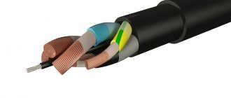
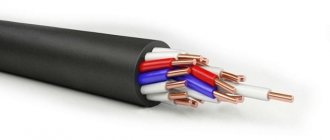
We have done a lot of work on structuring and created on this page a general list of brands of cable and wire products, dividing them into groups. This is very convenient if you want to select the specific brand of cable you need, as well as get more detailed technical information about it. We recommend using page search, for example, via CTRL+F in the browser.
To obtain information about the technical characteristics of the cable brand you need, simply follow the link to the appropriate page.
Power cables
Flexible
| KG-T | KG-HL | KGN | |
| KGE | KOG-1 | CNG | CPGS |
| KPGSN | KShVGT-10 |
With impregnated paper insulation for low voltage
| AAB2l | AABL | AABlG | AABnlG |
| AAG | AAShv | AAShng | ASB |
| ASB2l | ASB2lG | ASBG | ASBL |
| ASBnlShng | ASG | ASCl | ASShv |
| SB | SB2l | SB2lG | SBG |
| SBL | SG | CAAB2l | CAABl |
| CASB | TsASBL | TsASBnlShng | TsSB |
| TsSBl |
With impregnated paper insulation for medium voltage
| AOSB | AOSBG | OSB | OSBG |
With impregnated paper insulation for high voltage
| MVDT | MNAgShvu | MNASHv | MNASHvu |
| MNS | MNSA | MNSK |
With plastic insulation for low voltage
| AVBbShv | AVBbShng | AVVB | AVVBG |
| AVVG | AVVGz | AVVGng | APVG |
| VBBShv | VBBShng | VVB | VVBG |
| VVG | VVGz | VVGng |
With XLPE insulation for medium and high voltage
| APvV | APvVng | APvP | APvP2g |
| APvPg | APvPu | PvV | PvVng |
| PvP | PvP2g | PvPg | PvPu |
Based on halogen-free compositions produced by JSC NP Podolskkabel
| PBbPng-HF | PPGng-HF |
With cross-linked polyethylene insulation produced by JSC Elektrokabel Kolchuginsky Plant
| APvBbShp | APvBbShp |
GAMMALYON cable family
| GAMMALYON 331 | GAMMALYON K1 | GAMMALYON K3 | SUPERGAMMALYON K1 |
XLPE insulated cables produced by Novkabel (Serbia)
| N2XH | N2XS(F)2Y | N2XS(FL)2Y | N2XS2Y |
| N2XSEY | N2XSEYRY | N2XSY | N2XY |
| NA2XS(F)2Y | NA2XS(FL)2Y | NA2XS2Y | NA2XSEY |
| NA2XSEYRY | NA2XSY |
With XLPE insulation for medium voltage from REKA Cables
| A2XSYBY | AHXAMK-W 12/20 kV | AHXAMK-W 6/10 kV | AHXCMK-W TT 12/20 kV |
| AHXCMK-W TT 6/10 kV | AHXCMK-WTC/PE 12/20 kV | AHXCMK-WTC/PE 6/10 kV | AHXCMK-WTC/PVC 12/20 kV |
| AHXCMK-WTC/PVC 6/10 kV | HXCMK 12/20 kV | HXCMK 6/10 kV | HXCMK-HF |
| NA2XSE2Y |
With XLPE insulation for high voltage from REKA Cables
| AHXCHBMK | HXCHBMK |
With insulation made of cross-linked polyethylene and a shell made of PVC plastic compound produced by JSC "
| APvEV | APvEVng | APvEVngd | PvEV |
| PvEVng | PvEVngd |
With insulation made of cross-linked polyethylene and a shell made of polyethylene produced by JSC "
| APvEgaP | APvEgaPu | APvEgP | APvEgPu |
| APvEP | APvEPu | PvEgaP | PvEgaPu |
| PvEgP | PvEgPu | PvEP | PvEPu |
With insulation made of cross-linked polyethylene, armored with steel tapes produced by JSC "
| APvEBV | APvEBVng | APvEBVngd | APvEBP |
| PvEBV | PvEBVng | PvEBVngd | PvEBP |
With insulation made of cross-linked polyethylene, armored with steel wire produced by JSC "
| APvECV | APvEKVng | APvEKVngd | APvECP |
| PvEKV | PvEKVng | PvEKVngd | PvEKP |
Single-core armored cables with cross-linked polyethylene insulation produced by JSC "
| APvEAKV | APvEAKVng | APvEAKVngd | APvEAKP |
| PvEAKV | PvEAKVng | PvEAKVngd | PvEAKP |
Cables with cross-linked polyethylene insulation for voltage 1 kV produced by Kamsky Kabel LLC
| APvBbShv | APvBbShp(z) | PvBbShv | PvBbShp(z) |
| APvBbShng(A)-LS | APvVG | PvBbShng(A)-LS | PvVG |
| APvBbShp | APvVng(A)-LS | PvBbShp | PvVng(A)-LS |
Cables with cross-linked polyethylene insulation for voltage 10 kV produced by Kamsky Kabel LLC
| APvV | APvVng-LS | APvP | APvP2g |
| APvPg | APvPu | APvPu2g | APvPug |
| PvV | PvVng-LS | PvP | PvP2g |
| PvPg | PvPu | PvPu2g | PvPug |
Power cables according to foreign standards
| FROR | NA2XSEY | NAYY-J | NHMH |
| NHXHX FE180 | NHXCHX FE180 | NSHTOU | NYCY |
| NYRGY |
Cable 10 kV copper
A power cable designed for a voltage of 10 kV with a copper conductor is characterized by greater strength, reliability and increased service life. The copper core has high current conductivity and better contact than when using aluminum. If you are planning to lay a 10 kV cable, copper conductor will be the best choice if you require high efficiency in current transmission, as well as long service life. But if you need to reduce the project budget, then it is better to abandon copper cables and choose aluminum, the advantage of which is its lower cost compared to copper.
Installation cables and wires
Installation wires
| APBPP | Automatic reclosing | APPV | PBPP |
| PBPPz | PV1 | PV2 | PV3 |
| PV4 | PPV | PRKA | PUNP |
Power installation cables
| NYM | NYY |
Installation wires according to foreign standards
| H05V-K | JE-Y(ST)Y | N07V-K |
Control, control and communication cables
Telephone cables
| ATGM | TB | TBG | TG |
| TPV | TPVng | Chamber of Commerce and Industry | TPPBBbShp |
| TPPKShv | TPppZP | TPpPep | TPpPepB |
| TPPep | TPPep-NDG | TPPepB | TPPepBG |
| TPPepZ | TPPepZB | TSV |
Signal-blocking cables
| SBBbShv | SBBbShp | SBVBG | SBVG |
| SBSP | SBPBG | SBPu |
Control cables
| AKVBBShv | AKVVB | AKVVBG | AKVVG |
| AKVVGz | AKVVGng | AKVVGE | AKVVGEng |
| AKPVG | KVBBbShv | KVVB | KVVBBbG |
| KVVBG | KVVG | KVVGz | KVVGng |
| KVVGE | KVVGEng | KVKbShv | KPVG |
| KPVGE |
Control cables
| KGVV | CPV | KRSHS | KRSHU |
| KUGVV | KUGVVE | KUGVEV | CCMC |
| KUPV-P | KUPR | KUPR-P | KUPEV |
| KUPEV-P | MERSH-M |
Communication wires
| P-274M | Permanent residence permit | PKSV | PPZH |
| PRPVM | PRPPM | PTVZH | PTPZH |
| TRV |
Rural communication cables
| KSPZP | KSPZPB | KSPP | KSPPB |
Radio frequency cables
| RG | RD | RK | RK |
| RS |
Symmetrical zone cables
| ZKABp | ZKAKpShp | ZKASHp | ZKP |
| ZKPB |
Balanced low frequency cables
| TZB | TZBG | TZG | TZPABp |
| TZPABpShp | TZPASHp | TZSABp | TZSABpShp |
| TZSASHp |
Symmetrical high-frequency cables
| MKPpAShp | MKPpBpShp | MKSABp | MKSABpShp |
| MKSAShp | ICSB | ICSG |
Symmetrical communication cables with shielded pairs
| KMS-2 | KMS-2v | KMS-2u |
Cables for installation of alarm systems
| Checkpoint | KPVVng-LS | KPVEV | KPVEVng-LS |
| VSWR | KSVVG | KSVEV | KSVEVG |
| KSPV | KSPVG | KSPEV | KSPEVG |
Fireproof control, control and communication cables
| AKVVGng | AKVVGEng | KVVGEng | KPVVng-LS |
| KPVEVng-LS | Efficiency i ng - LS(ND) | SPOVng-FRHF | SPOVng-HF |
| SPOVPng-FRHF | SPOVPng-HF | SPOVENg-FRHF | SPOVENg-HF |
| SPOEVng-HF | SPOEVEng-HF | SPpVPng-FRHF | SPpVPng-HF |
| SPpVEng-FRHF | SPpVEng-HF | SPpEVPng-FRHF | SPpEVPng-HF |
| SPpEVEng-FRHF | SPpEVEng-HF |
Control cables based on halogen-free compositions produced by JSC NP Podolskkabel
| KPBbPng-HF | KPPGng-HF | KPPGEng-HF |
Control, control and communication cables according to foreign standards
| A-2Y[F](L)2Y | JH(St)H | JY(St)Y | LiYCY |
| LiYY | RE-2YCH | RE-2YF(L)2YR2Y | YSLY |
An example of choosing a cable cross-section for a voltage of 10 kV
It is necessary to select a cable cross-section for a voltage of 10 kV to power a 2TP-3 transformer substation with a power of 2x1000 kVA to power a slab warehouse at a metallurgical plant in the city of Vyksa, Nizhny Novgorod region. The power supply diagram is shown in Fig. 1. The length of the cable line from cell No. 12 is 800 m and from cell No. 24 is 650 m. The cables will be laid in the ground in pipes.
Table for calculating electrical loads according to 2TP-3
| Name of connection | Load | Power factor cos φ | ||
| Active, kW | Reactive, kvar | Total, kVA | ||
| 2TP-3 (2x1000 kVA) | 955 | 590 | 1123 | 0,85 |
The three-phase short-circuit current in maximum mode on RU-10 kV buses is 8.8 kA. The protection duration, taking into account the complete shutdown of the circuit breaker, is 0.345 seconds. The cable line is connected to the switchgear via a VD4 type vacuum switch (Siemens).
Fig. 1 – 10 kV power supply diagram
Calculation
The cross-section of a cable line for a voltage of 6 (10) kV is selected based on heating by the rated current, checked by thermal resistance to short-circuit currents, voltage losses in normal and post-emergency modes.
We choose a cable brand AABlu-10kV, 10 kV, three-core.
1. Determine the calculated current in normal mode (both transformers are turned on).
where: n – number of cables to the connection;
2. Determine the rated current in post-emergency mode, taking into account that one transformer is turned off:
3. We determine the economic section, according to the PUE section 1.3.25. The calculated current is taken for normal operation, i.e. the increase in current in post-emergency and repair modes of the network is not taken into account:
Jek =1.2 – the normalized value of the economic current density (A/mm2) is selected according to the PUE table 1.3.36, taking into account that the time of use of the maximum load Tmax = 6000 hours.
The cross section is rounded to the nearest standard 35 mm2.
Continuous permissible current for a cable with a cross-section of 3x35mm2 according to PUE, 7th ed. Table 1.3.16 is Id.t=115A > Icalc.av=64.9 A.
4. We determine the actual permissible current, in this case the condition Iph>Icalc.av. must be met:
The coefficient k1, which takes into account the temperature of the medium different from the calculated one, is selected according to table 2.9 [L1. p. 55] and table 1.3.3 PUE. Considering that the cable will be laid in pipes in the ground. According to Table 2-9, the standard ambient temperature is +25 °C. The temperature of the cable cores is +65°C, in accordance with the PUE, ed. 7, clause 1.3.12.
According to Table 4.13 [L5, p.86], we take the average monthly soil temperature for the hottest month (the most severe operating temperature regime) to be +17.6 °C (Moscow). I accept the ground temperature for the city of Moscow due to the lack of data for the city of Vyksa, and since these cities are located in the same climate zone - II, the error in the temperature difference will be within acceptable limits. We round the selected value of the soil temperature to the calculated value of +20°C.
To determine the average maximum air temperature of the hottest month, you can use SP 131.13330.2018 Table 4.1.
According to the PUE table 1.3.3, we select the coefficient k1 = 1.06.
Coefficient k2 – taking into account the resistivity of the soil (taking into account geological surveys), is selected according to the PUE 7th ed. table 1.3.23. In my case, the correction factor for normal soil with a resistivity of 120 K/W will be k2=1.
We determine the coefficient k3 according to the PUE table 1.3.26, taking into account the reduction in current load with the number of operating cables in one trench (in pipes or without pipes), taking into account that one cable is laid in one trench. We accept k3 = 1.
Having determined all the coefficients, we determine the actual permissible current:
5. We check the AABlu-10kV cable with a cross-section of 3x35mm2 for thermal stability in accordance with PUE clause 1.4.17.
Where:
- Ik.z. = 8800 A - three-phase short-circuit current in maximum mode on RU-10 kV buses;
- tl = tз + to.в =0.3 + 0.045 s = 0.345 s - protection duration taking into account complete shutdown of the circuit breaker;
- tз = 0.3 s – the longest protection operation time; in this example, the longest protection response time is in the overcurrent protection;
- tо.в = 45 ms or 0.045 s - total shutdown time of the VD4 type vacuum circuit breaker;
- C = 95 - thermal coefficient under nominal conditions, determined from table. 2-8, for cables with aluminum conductors.
The cross section is rounded to the nearest standard 70 mm2.
6. Check the cable for voltage loss:
6.1 In normal mode:
where: r and x - the values of active and reactive resistances are determined according to table 2-5 [L1.s 48].
For a cable with aluminum conductors with a cross-section of 3x70mm2, active resistance r = 0.447 Ohm/km, reactance x = 0.086 Ohm/km.
We determine sinφ, knowing cosφ. Let's remember the school geometry course.
If you do not know cosφ, you can determine it for various electrical receivers using the reference materials in table. 1.6-1.8 [L3, pp. 13-20].
6.2 In post-emergency mode:
From the calculations it is clear that the voltage losses in the line are insignificant, therefore, the voltage of consumers will practically not differ from the nominal one.
Thus, with the specified initial data, the AABlu-10 3x70 cable was selected.
To make cable selection easier, you can download all the literature that I used in this example in the archive.
Insulated wires
Insulated wires for overhead lines
| VOLLEY | ZALP-V | SAPssh | SAPt |
| SASPssh | SASPt | SIP-1 | SIP-1A |
| SIP-2 | SIP-2A | SIP-3 | SIP-4 |
| SIP-5 |
Winding wires
With plastic insulation
| PVDP | PP-V-100 | PP-V-80 | FPGA |
| PPT-V-100 | HDPE | PEP-V-100 | PEP-V-80 |
| PEPT-V-100 |
Winding wires with film insulation
| PPIPK-1 | PPIPK-2 | PPIPK-T | PPLBO |
| PPLLO |
Winding wires with fiber and enamel-fiber insulation
| APSD | APSDCT | PBD | POZH |
| POZH-700 | PSDCT | PSDT | PETVSD |
| PETSD | PESHO |
Winding wires with enamel insulation
| PNET-imide | PEVTL | PET-1-155 | PET-155 |
| PET-200 | PET imide | PETV | PETVM |
| PETD-180 | PETD-200 | PETKD | PEU-155 |
| PEF-155 |
Winding wires with paper insulation
| APB | APBU | APPA | PB |
| PBP | PBPU | PBU | PPA |
| PPA-1 | PPA-2 |
4.3. POWER CABLES WITH PLASTIC INSULATION FOR VOLTAGES 6 AND 10 KV
Power cables with plastic insulation for general use for voltages of 6 and 10 kV are produced in accordance with GOST 16442-80 single- and three-core with core insulation made of PVC plastic, PE, self-extinguishing PE, vulcanized PE, vulcanized self-extinguishing PE.
In Fig. 4.3.2. the designs of cables with PVC insulation of type AVVG for a voltage of 6 kV and with PE insulation of type APVG for a voltage of 10 kV are shown.
Fig.4.3.2. Designs of a cable with PVC insulation of the AVVG brand for a voltage of 6 kV (a) and a cable with PE insulation of the APVG brand for a voltage of 10 kV (b).
In accordance with TU 16.K71.025-86, as well as TU 16.K71.025-96, single-core cables with round or stranded copper or aluminum cores with cross-linked polyethylene insulation are produced. The design of a single-core cable for a voltage of 10 kV is similar to the design of cables for a voltage of 35 and 110 kV.
Cables with plastic insulation can be used for laying cable routes with an unlimited difference in their levels.
Cables for voltage 6 kV are made with three cores. They have a cross section from 10 to 240 mm2. The cable cores are copper or aluminum, similar to the cable cores for 0.66...3 kV. The cores are covered with insulation made of PVC plastic compound 3.4 mm thick, or PE insulated with a thickness of 3 mm. The core insulation, as in the case of low-voltage cables, has distinctive colors or digital numbering.
The insulated cores are twisted into a cable. The space between the cores is filled with PVC plastic. Belt insulation with a total thickness of at least 0.9 mm, or winding with plastic tapes, is applied over the structure, then a screen of electrically conductive PVC plastic with a thickness of at least 0.2 mm is placed on top of the PE belt insulation. Cables of all brands, except for cables in an aluminum sheath, have a metal screen on top of the electrically conductive screen made of two copper tapes with a thickness of at least 0.06 mm or aluminum tapes with a thickness of at least 0.1 mm, applied with a gap along the length of no more than 3 mm. On top of the shielding tapes in cables with PE insulation, winding is done with two PE tapes with a thickness of at least 0.2 mm, and in cables with PVC insulation - two PVC tapes with a thickness of 0.2 mm, two PET tapes with a thickness of at least 0.04 mm, one tape rubberized fabric or crepe paper. A PVC or aluminum sheath is applied over the tapes.
Cables for voltage 10 kV are manufactured single-core and three-core with round cores with a cross-section from 16 to 240 mm2. The cores are insulated with PE plastic compound, cross-linked PE, self-extinguishing PE. The core insulation thickness is 4 mm with a permissible deviation of 0.5 mm.
Shielding layers of electrically conductive PE or PVC with a thickness of 0.5 to 1.75 mm, depending on the diameter of the cores, are laid on the core under the PE insulation and on top of it. An aluminum sheath or a sheath of PVC plastic compound is applied on top.
Single-core cables of the PvP, PvPg, etc. brands for a voltage of 10 kV have a conductive copper core with a cross-section from 95 to 800 mm2. A semiconducting layer is applied over the core, covered with a water-swellable semiconducting tape. A screen of copper wires is placed on top of the tape, and a screen of copper tape, wrapped with water-swellable tape, is placed on top of the wires. The cable is enclosed in a PE sheath.
The designs of three-core cables for a voltage of 10 kV are to a certain extent similar to the designs of cables for 6 kV. The insulated conductors are twisted and the space between them is filled with electrically conductive PVC plastic compound, or conductive PE for cables with PE insulation.
A common electrically conductive screen made of the same materials is placed on top of the twisted conductors. A metal screen is placed on top of the common screen by winding two aluminum tapes with a thickness of at least 0.06 mm. Then the cable is wrapped with two PVC tapes or PET tapes, on top of which, depending on the brand of cable, an appropriate sheath and protective covers are applied.
Standard construction lengths of cables, depending on their cross-section and voltage, are given in the table.
Table 4.3.13 Standard construction lengths of cables
| Voltage 6 kV | Voltage 10 kV | ||
| Core cross-section, mm2 | Construction length, m | Core cross-section, mm2 | Construction length, m |
| Up to 70 | Not less than 450 | Up to 70 | Not less than 300 |
| 95…120 | 400 | 95…120 | 250 |
| 150 or more | 350 | 150 or more | 200 |
The following are the technical data of cables for voltages of 6 and 10 kV.
Table 4.3.14 Technical data of cables for voltages of 6 and 10 kV
| Cable brand | Number of cores | Nominal cross-section of cores, mm2 | |
| 6 kV | 10 kV | ||
| Cables with core insulation made of cross-linked PE | |||
| APvP | 1 | — | 95…800 |
| PvP | 1 | — | 95…800 |
| APvPu | 1 | — | 95…800 |
| PvPU | 1 | — | 95…800 |
| APvPg | 1 | — | 95…800 |
| PvPg | 1 | — | 95…800 |
| APvP2g | 1 | — | 95…800 |
| PvP2g | 1 | — | 95…800 |
| APvV | 1 | — | 95…800 |
| PvV | 1 | — | 95…800 |
| APVng | 1 | — | 95…800 |
| PvVng | 1 | — | 95…800 |
| Cables with core insulation made of PE | |||
| APASHvv | 1 | — | 16…240 |
| PASHv | 1 | — | 16…240 |
| APVG | 1; 3 | — | 16…240 |
| PVG | 1; 3 | — | 16…240 |
| APBbShv | 3 | — | 16…240 |
| PBbShv | 3 | — | 16…240 |
| APVG, APAShv, APBbShv | 3 | 10…240 | — |
| PVG, PAShv, PBbShv, PVB, PVBG | 3 | 10…240 | — |
| Cables with PVC core insulation | |||
| AVASHv | 1 | ||
| YOURV | 1 | ||
| AVVG | 1; 3 | ||
| VVG | 1; 3 | ||
| AVBbShv | 3 | ||
| VBBShv | 3 | ||
| AVVG, AVASHv, AVBBShv | 3 | ||
| VVG, VAShv, VBBShv, VVB, VVBG | 3 | ||
| Cables with core insulation made of self-extinguishing PE | |||
| APsAShv | 1 | — | 16…240 |
| PsAShv | 1 | — | 16…240 |
| APsVG | 1; 3 | — | 16…240 |
| PsVH | 1; 3 | — | 16…240 |
| APsBBShv | 3 | — | 16…240 |
| PsBbShv | 3 | — | 16…240 |
| APsVG, APsAShv, APsBBbShv | 3 | 10…240 | — |
| PsVG, PsAShv, PsBBbShv, PsVB, PsVBG | 3 | 10…240 | — |
| Cables with core insulation made of vulcanized PE | |||
| APvVG, APvAShv, APvBbShv | 3 | 10…240 | — |
| PvVG, PvAShv, PvBbShv, PvVB, PvVBG | 3 | 10..240 | — |
| Cables with core insulation made of vulcanized self-extinguishing PE | |||
| APvsVG, APvsAShv, APvsBbShv | 3 | 10…240 | — |
| PvsVG, PvsAShv, PvsBBShv, PvsVB, PvsVBG | 3 | 10…240 | — |
Table 4.3.15 Brands, design elements and areas of application of cables with cross-linked PE insulation
| Cable brand | Core material | Shell | Sealing | Application area |
| APvP | A | P | — | Installation in the ground and in the air, subject to fire protection measures |
| PvP | M | P | — | Same |
| APvPu | A | Pu | — | The same on difficult sections of the routes |
| PvPu | M | Pu | — | Same |
| APvPg | A | P | G | For laying in soils with high humidity and in damp, partially flooded rooms |
| PvPg | M | P | G | Same |
| APvP2g | A | P | yy | Same |
| PvP2g | M | P | yy | Same |
| APvV | A | IN | No | For installation in cable structures and industrial premises and dry soils |
| PvV | M | IN | No | Same |
| APvVng | A | Vng | No | The same for group laying |
| PvVng | M | Vng | No | Same |
Note:
PU - a shell made of polyethylene, reinforced with stiffening ribs, Vng - a shell made of DR-plastic compound of reduced flammability (non-flammable); d - longitudinal sealing of the screen with water-swelling tapes; 2d - transverse sealing with aluminum tape welded to the shell in combination with longitudinal sealing with water-swelling tapes.
Cables with cross-linked PE insulation shown in the table have the following nominal core cross-sections: 95, 120, 150, 185, 240, 300, 400, 500, 630, 800 mm2.
Technical parameters of single-core cables with cross-linked PE core insulation are presented below.
Table 4.3.16 Technical parameters of single-core cables with core insulation made of cross-linked PE grades PvP and APvP
| Nominal core cross-section, mm2 | Parameters of cables with XLPE insulation | ||||
| Insulation thickness, mm | Shell thickness, mm | Screen sections, mm2 | Outer diameter, mm | Weight, kg/km | |
| 95 | 4.0 | 2.5 | 16 | 31 | 1540 |
| 120 | 4.0 | 2.5 | 16 | 33 | 1800 |
| 150 | 4.0 | 2.5 | 25 | 34 | 2200 |
| 185 | 4.0 | 2.5 | 25 | 36 | 2500 |
| 240 | 4.0 | 2.5 | 25 | 38 | 3100 |
| 300 | 4.0 | 2.5 | 25 | 40 | 3700 |
| 350 | — | — | — | — | — |
| 400 | 4.0 | 2.5 | 35 | 44 | 4650 |
| 500 | 4.0 | 2.5 | 35 | 47 | 5700 |
| 630 | 4.0 | 2.5 | 35 | 50 | 7150 |
| 800 | 4.0 | 2.5 | 35 | 54 | 8800 |
ELECTRICAL PARAMETERS OF CABLES
Cables in finished form must be tested with an alternating test voltage with a frequency of 50 Hz for 10 minutes, the values of which are given below.
Table 4.3.17 Cable test voltages
| Rated cable voltage, kV | Test voltage value, kV |
| 6 | 11 |
| 10 | 15 |
Samples of 6 kV cables are tested at an alternating voltage of 15 kV for 4 hours. After laying and installing cables with plastic insulation, a cable line with fittings for a voltage of 6 kV is tested with a constant voltage of 35 kV for 10 minutes.
Samples of finished cables for a voltage of 10 kV are tested with an alternating voltage of 15 kV for 5 minutes. Cable lines with a voltage of 10 kV must be tested with a constant voltage of 50 kV for 10 minutes.
The electrical insulation resistance of plastic-insulated cables, recalculated per 1 km of length and a temperature of 20°C, must be within the values given in Table 13.18. The electrical resistance of the DC cores, recalculated per 1 mm2 of the nominal cross-section, must be within the values given in the table.
Table 4.3.18 Electrical insulation resistance of cables
| Insulation type | Electrical resistance, MOhm/km |
| Cables for voltage 6 kV | |
| With PVC insulation at 20 °C | at least 50 |
| With PE insulation at 20 °C | 100 |
| From vulcanizing PE at 80 °C | at least 50 |
| Made from vulcanizing self-extinguishing PE at 80 °C | at least 50 |
| Cables for voltage 10 kV | |
| With PVC insulation at 20 °C | at least 50 |
| With PVC insulation at 70 °C | not less than 0.05 |
| With PE insulation at 20 °C | not less than 100 |
| With PE insulation at 70 °C | at least 50 |
| With self-extinguishing PE insulation at 20 °C | not less than 100 |
| With self-extinguishing PE insulation at 70 °C | at least 50 |
Table 4.3.19 Electrical resistance of cable cores to direct current
| Cable type | Resistance Ohm/km |
| Single core with aluminum cores | no more than 29.1 |
| Three-core with aluminum conductors | no more than 29.4 |
| Single core with copper cores | no more than 17.76 |
| Three-core with copper conductors | no more than 17.93 |
Permissible cable operating temperatures must be within the values specified in the table.
Table 4.3.20 Permissible operating temperatures for cables
| Type of cable core insulation | Permissible core heating temperatures, °C | Maximum permissible core temperature at short circuit currents, °C |
| PVC plastic compound | 70 | 160 |
| Polyethylene | 70 | 130 |
| Cross-linked polyethylene | 90 | 250 |
The storage periods and conditions for cables with plastic insulation for voltages of 6 and 10 kV are similar to those for low-voltage cables.
Output, connecting and installation cables and wires
Cables and wires
| KuPe-A | KuPe-Az | KuPe-B | KuPe-IE |
| KuPe-IEB | KuPe-IEZ | KuPe-IEC | KuPe-IEOE |
| KuPe-IEOEB | KuPe-IEOEz | KuPe-IEOEK | KuPe-K |
| KuPe-OE | KuPe-OEB | KuPe-OEz | KuPe-OEC |
| MGTF | MGTFE | MGSHV | MGSHV-1 |
| MGSHVE | MLTP | MPO | MPOE |
| MS | MSTP | NV | NVM |
| NVME | NVE |
Connecting wires
| PVS | PVSP | PRM | PRS |
| PSG | SHVVP | SHVG | SHVD |
| ShVL | Ball screw | ShVP-2 | SHVPT |
| SHOG | SHOG-S | ShPS | ShR |
| ShRO |

