The KVVG cable belongs to the group of control cables used in industry when connecting various machines, devices, control devices and other automated equipment.
The main functional difference between control cables is the scope of application. They are made using a technology similar to that used for conventional power wires, but at the same time they have thinner insulation, the breakdown resistance of which is significantly lower than that of power wires. Control cables, and KVVG in particular, are intended exclusively for transmitting a control signal to various machines and devices. We can say that they occupy an intermediate position between power cables and communication cables - telephone, network and other telecommunications.
Please note: unlike telecommunications, control cables, including the KVVG cable, are not low-current. KVVG, in particular, can withstand an alternating current voltage of 660 V, and a direct current voltage of 1000 V.
Definition and differences
First, one persistent myth or controversy must be addressed initially. Many less experienced and qualified “specialists” often confuse it with a VVG type cable, considering them to be the same type or modified. Partly, similar production technology and the structure of the cores contribute to this misconception, but in fact these are completely different products in terms of purpose (scope of application).
In the first case, there is a common VVG cable, which belongs to the power group, that is, those that are used for direct transmission of electricity. Due to such conductors, voltage is supplied to the key power and actuating mechanisms of the equipment.
The second cable is not at all a modernization of the previous one, but a full-fledged self-sufficient product that belongs to the control category. Its main difference from power is that the transmitted low-voltage voltage is used not to ensure the operation of components and mechanisms, but to control it. It is used for connection with ballasts, automation, relay protection devices, etc.
In addition, there are a number of design differences:
- Color marking of current-carrying conductors. Control cables KVVGng or KVVGEng have twisted cores. Each twist necessarily contains a counting and guide wire, the insulation of which is blue and red, respectively. The power cable, on the contrary, consists of individual elements with insulation of different colors,
- Thickness of the insulating layer. According to regulatory documents, control cables KVVGng, KVVGEng and others have insulation of a thinner thickness than their analogue cross-section of the power type. For example, for a 2.5 mm2 core, this figure is 0.7 mm and 0.8 mm, respectively,
- Heating temperature. The maximum threshold for power cables is 80ºС, while for the control cables KVVGng and KVVGEng it is lower - 70ºС,
- Elasticity. This parameter is responsible for the ability to bend during installation. For a power cable, the minimum radius is about 10 outer diameters, and for KVVGng or KVVGEng - at least 4.
Control and power cables - differences and similarities
Power and control cables have a lot in common:
- production technology;
- the presence of one or more cores isolated from each other;
- · aluminum or copper are used as a conductor, and therefore the conductivity of conductors of the same cross-section is the same;
- insulation material – PVC, rubber, polyethylene;
- Cable versions armored with steel tape can be produced to protect against external mechanical influences. In this case, the name contains the letter B.
- can be shielded (the letter E is present in the marking). In the case of a control cable, the screen is designed to protect it from the effects of external electromagnetic interference; in a power cable, it protects the environment from the field of currents flowing through the cable.
But since these cables have different purposes, they also have differences.
Power cable
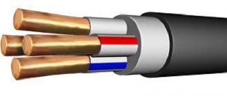
The power cable is available with a number of cores from two to 5:
- 2 – supply of phase and neutral to the consumer (single-phase voltage 220V);
- 3 – supply of phase, neutral and grounding;
- 4 – three phases and zero (three-phase voltage 380 V);
- 5 – three phases, neutral and ground.
The cross-section of each core, which can also be multi-wire (for large cross-sections), varies from 1.5 to 1600 mm2. The cable is designed for voltages up to 1000 V.
Control cable
The cores are single-wire only. Their number can be as follows: 4, 5, 7, 12, 14, 19, 27, 37, 52, 61. The cross-section of the core is from 0.75 to 6 mm2. Inside the cable, designed to operate at voltages up to 0.66 kV, the cores are grouped into layers - coaxial layers that differ from neighboring ones (outside and inside) by the angle of inclination of the cores to the cable axis. In each layer there are two wires, called counting wires, blue and red, which make it easier to find a specific core.
Table 1. Difference between control and power cable
| Parameter | Power cable | Control cable |
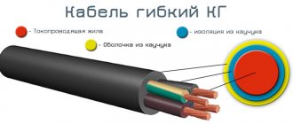
| Marking | No “K” at the beginning of the name (exception: KG – flexible cable) | The presence of the letter “K” at the beginning of the name, meaning “control” |
| Number of cores | 2 – 5 | 4 – 61 |
| Core cross-section | up to 1600 mm2 | up to 10 mm2 (aluminum); up to 6 mm2 (copper) |
| Stranded core | Possible with large core cross-section | Can not be |
| Having cured | No | from one to several (located coaxially) |
Marking of cable products
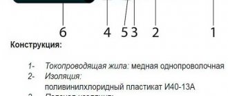
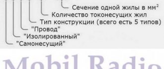
Those designations that are incomprehensible at first glance, which have already been mentioned above, have a clear basis, since they determine the technical characteristics of individual products and the scope of their possible application. The decoding of the abbreviations KVVGng, KVVGEng is as follows:
- K - indicates that this is a control cable,
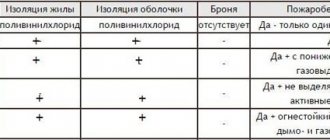
- B (first) - means that the conductors have polyvinyl chloride (PVC) insulation,
- B (second) – a PVC shell is used,
- G – lack of protective cover,
- E – the presence of a shielded ball made of aluminum foil,
- NG – outer shell made of plastic compound that does not support combustion.
It should also be taken into account that since the designation does not have the letter A (aluminum) at the beginning, the conductors are copper.
Various indications for these cables
According to clause 4.1 e)-g) GOST 31996-2012 decoding for these cables VVG , VVG ng (A) and VVG ng (A)-LS:
f) on performance in terms of fire danger indicators:
- flame retardant when installed alone ( no designation );
- flame retardant during group installation ( ng ): according to category A - ng(A) ,
- flame retardant when laid in groups, with reduced smoke and gas emissions ( ng-LS );
g) according to the cross-sectional shape of the cable:
- round (no designation);
- flat (P).
In accordance with clause 6.3.2, cables of versions “ng” and “ng-LS” should not spread fire when laid in groups. Test category A is established in the technical specifications for cables of specific brands.
According to clause 6.3.3, cables of “NG-LS” versions must have low smoke and gas emissions during combustion and smoldering.
Final transcript
VVG is a cable with copper conductors, with insulation and sheath made of polyvinyl chloride plastic, which is flame retardant when laid alone.
VVGng(A) is a cable with copper conductors, with insulation and sheath made of polyvinyl chloride plastic compound of reduced fire hazard, which is flame retardant when laid in groups according to category A.
VVGng(A)-LS is a cable with copper conductors, insulation and sheath made of polyvinyl chloride plastic compound of reduced fire hazard, non-flammable when laid in groups according to category A with reduced smoke and gas emissions.
VVG-Png(A)-LS is a cable with copper conductors, insulation and sheath made of polyvinyl chloride plastic compound of reduced fire hazard, flame retardant according to category A, flat
Design features, characteristics of KVVGng
This type of product is used to transmit alternating current with voltages up to 660 V and 100 Hz, as well as direct current - up to 1000 V. As follows from the decoding, copper conductors are used here. They can be combined into several concentric strands (one on top of the other), with the obligatory presence in each of them of a countable pair of cores (red and blue insulation). Their number can vary depending on the need, cross-section (0.75...10 mm2), and ranges from 4 to 37 pieces. Accordingly, the outer diameter of the wire can range from 7.6 mm (for a 4 × 0.75 cable) to 25.3 mm (for 10 × 10). The last pair of letters of the KVVGng marking means that the outer layer has a reduced degree of flammability. That is, it can be used with increased fire safety requirements.
The bending radius of cables with an outer diameter of up to 10 mm is at least 3D, and for larger ones - 4D.
Cables of the KVVGng type are used to organize fixed connections in an open manner. Laying in a trench is also allowed, but it should be taken into account that the cable is not armored.
Method for reliable connection of control cable cores
The connection of control cable cores has traditionally been the cornerstone in creating a reliable and durable control circuit. Oxidative processes occurring in the splice area often lead to an increase in contact resistance, loss of electrical contact and, as a result, a failure in the circuit. The 3M company offers to solve this problem using Scotchlock® connectors. These connectors, operating on the principle of a U-shaped piercing contact (Fig. 1) , have found the widest application in electrical installation practice. The use of Scotchlock® connectors allows you to simply, quickly and efficiently install contact connections and wire branches without stripping the insulation, providing a high level of protection of the contact connection from environmental influences, preventing extremely undesirable oxidation of electrical contacts.
Rice. 1. Electrical connectors with U-shaped piercing contact Scotchlock®
When installing connections and branches of control cables, especially in aggressive environments, Scotchlock® connectors filled with hydrophobic gel are used. This is due to the fact that the main condition for long-term operation of a contact connection is the requirement to protect the electrical contact from moisture. In conditions with high humidity, conventional unprotected contact connections do not perform satisfactorily. Very soon the contact is covered with an oxide film, its oxidation and degradation begin, which in turn leads to a sharp increase in electrical resistance and loss of contact.
For use in wet environments, the well-proven models of Scotchlock® connectors UY2, UR2, 314, 316IR and MGC are most often used. They provide installation of connections and branches of wires with a cross-section range of 0.5–2.5 mm2.
During installation, the metal contact located inside the connector cuts through the insulation of the wires and comes into strong contact with the conductors, and the hydrophobic filler ensures reliable protection of the connection.
The Scotchlock® connector ensures quick and easy installation. It is enough to simply insert the ends of the wires to be connected into it, squeeze the cover and the connector body with pliers with parallel jaws - and the installation is completed. Removing insulation from the cores when installing a connection using a Scotchlock® connector is not required. The installation sequence of the Scotchlock® connector is shown in Fig. 2 .
After the connection is made, the hydrophobic filler located inside the Scotchlock® connector protects the connection from moisture.
Scotchlock® connectors with a hydrophobic filler are ideal for use not only in conditions of high humidity, but also when operating electrical contacts outdoors - in the open air and even in the ground.
| a) take the Scotchlock® connector | b) insert the wires into the connector until they stop at its back wall |
| c) press the cover to make the connection | d) installation completed |
Rice. 2 . MGC connector installation sequence:
Design features, characteristics of KVVGEng
This type of product has the same voltage specifications as the previous one. The main condition for its use is increased fire safety requirements, non-propagation of flame when using a group method of laying cables. The conditions for laying KVVGEng are similar - openly, in boxes or tunnels.
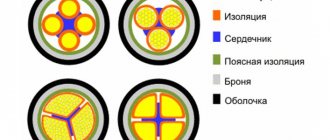
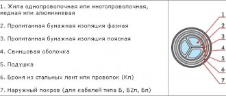
Structurally, KVVGEng consists of the following key components:
- Single-wire copper conductors,
- PVC core insulation,
- PVC insulation (wrap, belt) twists,
- Screen (aluminum foil). In decoding it is designated as E,
- External protective layer made of PVC. As a rule, a hose based on NGP plastic compound, etc., is used.
Unlike KVVGng, cable type KVVGEng has a larger minimum bending radius, equal to approximately 6D. The number of cores can similarly range from 4 to 37 pieces. At the same time, the maximum cross-section of one core is only 6 mm2.
Cables of the KVVGng and KVVGEng types are widely used to organize control lines responsible for organizing testing of the serviceability and accuracy of the main equipment. Their specialty is low-voltage lines, and the insulation is thinner, which reduces the overall cost in comparison with power analogues. It is not armored and therefore installation instructions must be observed.