When planning energy supply at a facility, one of the important issues is saving materials. Laying a separate power line from the circuit breaker to each consumer is irrational, so nodal points and branching wires are made on the power main. Each additional connection requires the installation of a junction box.
What is a distribution (junction) box
This is an electrical product, which is a closed housing made of metal or dielectric material. The second option is preferable, provided that the material is sufficiently reliable from a fire safety point of view. That is, it must be non-flammable, or at least not support combustion.
Inside, power cables and supply wires are connected for consumers or switching devices. The junction box must provide protection for internal connections from dust, moisture, and foreign objects. In addition, the product prevents accidental contact with exposed areas of the electrical circuit (current-carrying busbars, contacts).
The shape of the box, as well as its dimensions, are not regulated - the format of the product is selected based on the installation conditions. However, manufacturers adhere to certain standards for compatibility with various fittings and components.
Material
When choosing, you should focus on durable and fireproof material, characterized by a high level of heat resistance. Most often on sale you can find plastic models made of polyamide, polypropylene or cast fluoroplastic. Such products will not decompose under the influence of active compounds.
The boxes are quite durable and have good insulating characteristics. Unlike metal samples, they are more resistant to wet conditions. When ignited, the plastic does not burn, but begins to melt.
Metal boxes provide greater protection for connections. To do this, choose corrosion-resistant tinned steel or aluminum alloys. During a fire, the connections are well protected, which will allow time for the power to be turned off.
Types of distribution boxes
Based on the body material, boxes are divided into:
- Metal - for installation in rooms built from flammable materials (wood, plastic), or on walls insulated with flammable material. They may have a dielectric layer inside to reduce the likelihood of unauthorized contact closure.
- Plastic are the most common due to their low manufacturing cost. They are made either from non-flammable material, for use in conditions of high fire danger, or from materials that do not support combustion. That is, the junction box in any design should not become a source of fire, even if the wiring ignites inside.
According to installation conditions:
- For indoor installation. Designed for installation in walls and cladding. They consist of a body, which must be firmly held in the supporting structure, and a flat cover. In turn, the cover must be removable for access to the contact group or twists. In such boxes, the thickness of the case can be thinner, because it does not bear the structural load.
As a rule, built-in boxes are made in a round shape. When installing into a monolithic wall, drilling an installation hole using a crown is much easier. For installation in drywall, you can use rectangular (square) housings. It is easy to cut such a hole in the gypsum board.
From the point of view of connecting wires, it is more convenient to work with a square (rectangular) case. - For outdoor installation (non-sealed) - conditions of use - indoors or closed cabinets. The housing is both protection from the external environment and a strength element of the structure. Therefore, it must be thicker and stronger.
To prevent foreign objects from getting inside, the outer boxes are equipped with sealing clamps for wires. - For outdoor installation (sealed). Installation of the distribution box outdoors involves direct exposure to water, frost, and fog. Since water is a conductor, the inside of the housing must be dry. Therefore, sealed boxes have a rubber seal along the sealing contour of the lid, and crimp (collet) clamps for inserting wires.
- Of course, additional equipment of products (moisture protection, etc.) increases the cost. Therefore, when choosing a package, we usually proceed from the principle of reasonable sufficiency.
Junction boxes can be equipped with a ready-made set of connectors for wires. Or you buy an empty case, and the fittings are selected separately.
Where can I buy
You can resolve the issue as quickly as possible by visiting the nearest specialized store. The optimal option, in terms of price-quality ratio, remains purchasing from the AliExpress online store. Mandatory long waits for parcels from China are a thing of the past, because now many goods are in intermediate warehouses in destination countries: for example, when ordering, you can select the “Delivery from the Russian Federation” option:
| 3-pin waterproof distribution IP68 box | Distribution box, IP67 housing | Junction box, IP65 |
| 3-way distributor box, IP68 | Distribution box 2/3/4/5/6 way, IP68, 45A/450V | Mini junction box IP66, size 47*28*18mm |
Connecting switches
The input wires are connected to the switches according to the principle of similarity. There are 2-3 wires from the power source. Each of them is responsible for phase supply, disconnection and grounding.
Accordingly, when connected, they will connect like this:
- shutdown to shutdown;
- ground to ground;
- summing up to summing up;
There is nothing complicated about connecting an outlet. The principle of color similarity, phase and working zero determination also works here. Each color corresponds to the color of the opposite contactor.
Layout
To begin, make a flowchart that makes it clear which consumer groups need to be created. Then the power on each branch is calculated.
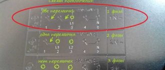
There are two methods of load distribution:
- Interior. An introductory (basic) box is organized in each room. Power lines are laid from the base points to the input distribution board. Each line is started on a separate machine. In the case where powerful electrical equipment (boiler, air conditioner, electric stove) is installed in some rooms, a separate line of power sockets is laid. Then the basic distribution box is disconnected for each consumer in the room. For this purpose, additional junction boxes can be installed. An approximate diagram of the basic boxes looks like this:
- By consumer groups. Separate lines are laid for the lighting of all rooms, for the low-load socket network (TV, computer, table lamps), and for the power socket network. These wires are also connected to the circuit breakers of the input panel. Again, distribution boxes are installed along each line at the tapping points to individual consumers.
Next comes the dirty work: actually installing the boxes and laying the cable lines.
Hidden installation
Wiring is laid between the nodal points (where the boxes are installed). Since the installation is hidden, the walls are grooved for the cable, and the boxes are installed on alabaster. The prepared wires are removed from the installed boxes for connection. The length of the free ends should provide the possibility of connection without interference, and allow for 2-3 alterations (with cutting off the used conductors).
The method of connection does not matter (soldered twist in the illustration), the main thing is to understand the principle itself. For cables, the flush-mounted boxes have marked holes. In this case, tightness is not required; there will be a wall and plaster around it. The secret is that alabaster, diluted to a creamy consistency, when installing the box, fills all the cracks, grooves and extra holes.
The result is a monolith with dielectric walls. The planting depth is calculated taking into account the thickness of the wallpaper and the shape of the lid.
Outdoor installation
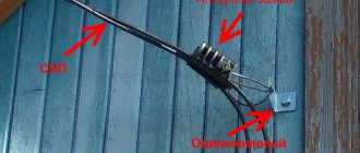
The principle of connecting the wiring is the same, but the installation is done differently. First, the junction boxes are installed, then the external cable is connected to them. Since the housing provides protection from dust and moisture, the cables are routed inside using sealing clamps.
For outdoor installation, collet clamps are used.
The wires must be color-coded: in single-phase versions, zero, phase, and protective grounding. It is not possible (especially before connecting the ends of the cable) to hang tags indicating the purpose of the wires. After final installation, it is enough to record the purpose of the wires on the diagram. You can stick short symbols on the inside of the cover for ease of further maintenance.
If the methods of how to disconnect a distribution box on a power line are clear: we simply connect the input and output wires by color, then connecting a switch is a completely different scheme.
Various ways to connect switches and lighting fixtures
- Classic connection using a junction box.
The neutral and phase wires are inserted into the box. For simplicity, we will leave protective grounding out of brackets. The neutral wire is directly connected to the lamp. The phase is supplied to the switch, then transits through the box and connects to the second input of the lamp. From an installation point of view, 3 two-core wires enter the junction box. Using the same principle, two or three-key switches are connected. Only more transit phase wires (from keys to lamps) will pass through the box. If you connect several lamps to one switch, there is no point in installing several distribution boxes. You can connect lamps in parallel, starting from the first lamp. In this case, the switch will be a group switch. - Wiring for a lamp without junction boxes.
In this case, a power cable is inserted from the nearest distribution box into the switch housing. The neutral wire is connected to the lamp directly, and the phase wire is opened by a switch. On the one hand, this saves one box. On the other hand, the cable is laid irrationally and must be inserted into the switch housing from below or from the side. While according to the standard generally accepted scheme, the main line runs along the ceiling. And from the ceiling junction boxes, the wiring goes down to the sockets or switches.
Internal structure and switching principle
Distribution boxes with terminals
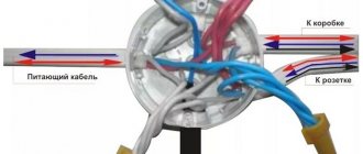
The internal space of a typical box is conventionally divided into 4 zones with external walls adjacent to them. Each of them has a perforated hole (usually round) into which cable bundles are inserted. One of them comes from a distribution board with a linear machine and contains phase and neutral conductors.
If switching is necessary, wiring is started from two adjacent sides coming from switches and sockets located in this branch. Upon completion of all required connections, the cable cores are routed out in a loop towards the adjacent area of the room.
When end boxes are installed in dead-end spaces, the number of holes involved may be fewer.
The dimensions of the internal spaces of the distribution device allow elements of standard connectors to be placed in it.
Methods for connecting wires in junction boxes
Putting the wires inside the box is half the battle. Now you need to choose a connection that is reliable and easy to maintain.
All cable line connections are divided into two main categories:
- Detachable, that is, the wiring can be disconnected and reconnected many times, without critical damage to the wire or connecting device. For example, a screw connection on terminal blocks.
- One-piece, that is, when the conductors are separated. the connection is destroyed. There is no big problem with this, it’s just that the cable gets shorter each time, and the connecting devices have to be purchased again.
The type of splicing when disconnecting boxes is selected based on the design of the overall network. If you plan to periodically disconnect one or two branches from a common box, it is better to choose a screw connection or reusable quick-release terminals.
For permanent connections that will not be dismantled for many years, the same terminals are used, only for one-time use. Despite the obvious drawback: the impossibility of reuse, such terminals provide more reliable contact compared to reusable ones.
Important! The listed methods allow you to install cables using different conductors: for example, aluminum and copper. In this case, the metals do not touch, and electrocorrosion does not threaten loss of contact.
If you use only copper conductor both in the backbone network and in subscriber branches, there are cheaper ways to permanently connect the wires:
- Twisting with welding. Creates reliable contact, without the risk of sparking and heating of the wiring under heavy load.
The connection is simple, but requires special equipment. As a last resort. You can melt the copper tips with a portable gas torch. - Twisting with soldering. It is not as reliable as with tip reflow, but when using refractory solders, the connection practically does not lose strength, even when heated.
The advantage is accessibility. A powerful soldering iron is easier to find than welding equipment. The basic rule: strength is ensured by twisting; we simply fill the voids with solder, improving contact. - Twisting with mechanical fixation (crimping). A questionable method, since there is a possibility of damage to current-carrying wires.
- There is nothing to say about ordinary twisting: although it is not prohibited, this technique is practically not used.
Direct connection (disconnection)
Is it possible to organize electrical wiring without junction boxes? When branching no more than 2 lines, it’s easy. Several conditions must be met:
- If the connection is made by twisting, soldering with refractory solder is required. Crimping can be used.
- "T" shaped connections are undesirable; it is better to make a "Y" shaped branch.
- After connecting and checking the quality of contact, the splice area must be carefully insulated and protected from moisture. Especially if the connection is made in hidden wiring (plaster wall) or on the street.
Installation
In places where the main electrical wire is divided into separate lines, distribution boxes are installed in the building. A special feature of their installation is the need to install a distributor. boxes at branching points according to the electrical wiring design.
Usually, a place is chosen in the corner jambs, and depending on the height of the ceiling, 20-30 cm from the ceiling.
Installation is carried out in accordance with the following algorithm:
- At the point where the main wire enters, a distribution box is installed and firmly fixed in a pre-prepared place.
- Wires for power supply terminals for sockets, switches, chandeliers and lamps, terminals for powering stationary electrical appliances - air conditioners, gas boilers, boilers are carried into a box to a length of 5-7 cm.
- The wires are marked inside the box.
- The cable entry diagram is drawn onto the room's electrical wiring plan, with numbering and indication of the entry features (if necessary).
- The wiring connection is being made.
- The twists are reliably insulated either with insulating tape or special caps.
- The twists are recessed inside.
- The lid closes.
- External work is being carried out to fix it with plaster or putty.
Compound
wire connection lines
Installation of connections of electrical wiring lines into a complete power supply system is carried out according to a predetermined scheme.
The calculation of loads and wiring cross-sections is determined at the design stage, but practical implementation is carried out as follows:
- The ends of the wires are 1.5-2 cm free from insulation.
- In the case of laying wiring from cables that have double insulation, the outer insulating layer is removed to a length of 4-5 cm.
- The wires are connected according to color, this is the simplest and easiest connection.
- Using pliers or other electrical installation tools, each twist is crimped and insulated either with electrical tape or a plastic cap.
- If the box contains terminal blocks or mounting blocks, then installation is carried out using a screw clamp, by pressing wires of the corresponding color on one plate.
- After connection, the wires are checked and placed in the box, and the lid is closed.