If you find yourself here, then you have a task: to introduce electricity into your private home. And of course there are many questions in my head: which cable to choose? Which introductory machine should I install? Which counter should I choose? And in the end, how to combine all this into one properly working system. We would like to share our experience of how we carried out air entry into our country house. Well, now let's look at all our steps and thoughts in order. What we had: on the street there was a concrete pole with main wires, aluminum wires were connected from it on twists, then they were connected to the output wire at the gander on the roof.
It was necessary to replace all this old stuff with something modern, and the best option to do this was using 2x16 SIP wires.
Entry into the house with SIP wire
Perhaps someone is not familiar with the abbreviation SIP, which stands for self-supporting insulated wire.
It was invented to replace conventional aluminum wires, which are sometimes tampered with by scrap metal collectors. In essence, this is an ordinary twisted aluminum wire, but now it is in insulation, which must be removed, and therefore SIP cables have become of no interest to metal assemblers.
To enter the house with SIP wire, we purchased the following fittings for SIP and other switching elements in the store:
- SIP wire 2x16 long - 12 meters;
- Anchor clamp for SIP cable 4x16 - 2 pieces;
- Branch piercing clamps - 2 pieces;
- Galvanized corner with holes - 1 piece;
- Sealed box with DIN rail - 1 piece;
- PVC corrugation with fastenings - 20 meters;
- Two-core copper cable AVVG 2x10 - 15 meters.
- Automatic switch EKF BA47-73 - 2 pieces.
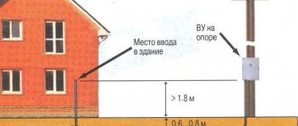
From our side: a corner was installed on the gable of the house using a bolted connection, to which an anchor wedge clamp for SIP was attached.
Installation of SIP on the gable of a house
SIP anchor clamp
Since the SIP cable has polyethylene insulation, according to the PUE, it cannot be brought into the house!
7.4.36. In fire hazardous areas of any class, cables and wires must have a cover and sheath made of flame retardant materials. The use of cables with flammable polyethylene insulation is not allowed.
Based on the above, in order to further connect electricity to the house, an AVG aluminum cable with a cross-section of 10 mm2 was used, which was pre-tightened into a PVC corrugation.
To connect the SIP wire and the AVVG cable, nut-type connectors could be used. But since the cable will pass through the house, to protect it, an automatic switch was installed, which made the connection between these conductors.
Automatic entry device
From the side of the dacha cooperative: the electrician climbed onto the pole and secured another anchor clamp to the metal clamp. Then in this clamp, using a wedge, he secured the SIP wire. And with the help of branch clamps with piercing the insulation of the SIP, we connected our wire to the main line
Installation of SIP on a pole
Branch piercing clamp for SIP
Drawing up a diagram
It’s easy to make a wiring diagram in an apartment with your own hands. To do this, it is recommended to use a photocopy of the housing plan, on which you can conveniently mark the installation locations of sockets, switches, lamps and other components. We described in detail how to draw up a wiring diagram before repairs in the article: https://samelectrik.ru/kak-sostavit-sxemu-elektroprovodki-pered-remontom.html. The main points are outlined below.
The starting point of the diagram is the location of the distribution panel in the apartment. Usually this place is the corridor, next to the front door, at a height of approximately 1.5 meters from the floor.
When drawing up a diagram, we recommend that you consider the following tips, norms and rules:
- In apartments it is prohibited to groove load-bearing walls, as well as to make horizontal and vertical grooves. We will talk about this in detail below.
- The route of apartment electrical wiring must run strictly vertically and horizontally along the walls. This requirement ensures that there is less chance of damage. For example, by the location of the socket you can find out exactly where the cable goes so that you don’t accidentally drive a nail into it when hanging a picture. Ideally, it is recommended to locate the wire in the wall using a special tool before driving a nail. Please note that in Khrushchev and other panel buildings the cables are laid in channels in the slabs. Due to the rigidity requirements, the channels can run diagonally.
- The route should only be turned at right angles.
- It is best to lay a line at the top of the wall, at a distance of 20 cm from the ceiling (this height will ensure minimal likelihood of mechanical damage and will not affect the ease of repair). You can also run the wiring on the floor rather than the ceiling using a special electrical baseboard.
- Switches in the apartment should be located at the entrance to the room, on the side of the door handle. The height of the switches is not standardized according to GOST and SNiP, but, as a rule, it is either 80 cm or 150 cm. According to the European standard, it is better to install the switches lower, besides, it will be more convenient for children to turn on the light if necessary.
- Sockets are mounted at the bottom (20-30 cm from the floor), but if necessary they can be placed at any height (for example, in the kitchen above the countertop). Recommended for 10 sq. meters of room, install at least one socket, and at least 1 socket per room. In the kitchen, the number of products should correspond to the number of household appliances; at least 4 pieces are recommended. This is stated in SP31-110-2003 “Design and installation of electrical installations of residential and public buildings”, paragraph 14.27. The distance from the mounting point to the door and window should not be less than 10 cm.
- Every room must have a distribution box.
- Before drawing up a project for electrical wiring in an apartment, carefully plan the location of household appliances and furniture. It happens that after electrical installation work, products may be covered by furniture, or cords from household appliances do not reach the power source.
- The bathroom must have at least 2 sockets (one for connecting a washing machine, the second for a hair dryer). But read the article “sockets in the bathroom” about their correct location. In short, outlets should have protective curtains or be located in an area with the least chance of splashing.
You will probably find these articles useful:
- electrical wiring diagram in a three-room apartment;
- electrical wiring diagram in a one-room apartment.
Selection and calculation of the introductory machine
To protect the input cable, we need to select a circuit breaker for input into the house, which is selected according to the rated current flowing through it when consumers are turned on. In order to determine the rated current of the input circuit breaker, it is necessary to calculate the total power of all consumers in the house. We have compiled a table showing the name and power of the consumer
| electrical appliance | Power, W |
| LCD TV | 200 |
| Fridge | 600 |
| Boiler | 2000 |
| Iron | 1500 |
| Electric kettle | 1800 |
| Microwave | 1000 |
| Computer | 500 |
| Lighting | 800 |
| Well pump | 1000 |
| Air conditioner | 400 |
| Total | 9800 |
But since consumers cannot all be turned on at the same time, the demand coefficient is used for calculations, which is equal to 0.7 when the number of receivers in the room is from 5 to 200.
Using the formula, we determine the estimated total active power of consumers:
Calculation of active power of all consumers
Next, you need to calculate the total total power of consumers in the house using the following formula:
Calculation of the total power of all consumers
where cos phi is the power factor, for residential premises it lies in the range of 0.96 - 0.98.
Now we determine the calculated current for a single-phase network using the following formula
Rated current calculation
where Unom is the rated voltage of a single-phase network equal to 220 V
Now, based on the calculated current, we select the rating of the input circuit breaker. For internal power supply of apartments and houses, modular circuit breakers of standard ratings are used:
6, 10, 16, 25, 32, 40, 50, 63 A
The rated current of the machine must be equal to or the nearest greater from the standard range.
In our case, for an introductory machine, we need a machine with a rated current of 32 A
Package of documents for connecting electricity
To connect electrical networks to a building or site, it is necessary to draw up and submit an application in the appropriate form to the organization that provides power supply to the given territory and obtain from it a document permitting connection to electrical networks. The entire process of electrifying the facility is presented in the following picture.
The following set of documentation is attached to the application to the energy supply company:
- copies of identification codes and civil passport of the object owner;
- a set of copies of documents confirming property registration.
Some energy supply companies, in addition to the above documents, may require a project for the electrification of the facility, with a detailed plan for the placement of electrical appliances, equipment and their technical characteristics in terms of power. When connecting electricity to the site, it is necessary to attach to the application a permit for construction and installation work on it. Sometimes, management companies require that the application be supplemented with original contracts and acts confirming the accuracy of the copies.
After making a positive decision, the division of the district electrical network (RES) is obliged to develop specifications within 1 month for connecting electricity to a private house or plot, which the owner must complete within up to 2 years. The technical specifications indicate what type of cable or wires must be used - for three phases or one. Only if all technical requirements are strictly met, is it possible to connect the facility to electrical networks. After all points of the specifications have been completed, a connection project is developed.
Selection and calculation of input cable
The aluminum cable AVVG 2x10 mm2 was mentioned above, perhaps you were wondering where the figure came from? Everything is very simple, before purchasing we made a preliminary calculation of this conductor.
The cross-section of the cable for entry into the house is calculated based on the maximum permissible current at which heating of the conductor will not cause damage to the insulation of the input cable.
Those. our cable must withstand the current for a long time at which the thermal release of the machine will operate.
The thermal release current is assumed to be 15-20% greater than the rated current of the machine and is calculated using the formula:
Calculation of thermal release current
Now from the PUE, in tables 1.3.4 for copper conductors and 1.3.5 for aluminum conductors, we select the required cross-section of the cable laid in one pipe from the “ one two-core ” column, equal to or the nearest larger.
Table 1.3.4. Permissible continuous current for wires and cords with rubber and polyvinyl chloride insulation with copper conductors
| Cross-section of current-carrying conductor, mm2 | Current, A, for wires laid | |||||
| open | in one pipe | |||||
| two single-core | three single-core | four single-core | one two-wire | one three-wire | ||
| 0,5 | 11 | — | — | — | — | — |
| 0.75 | 15 | — | — | — | — | — |
| 1 | 17 | 16 | 15 | 14 | 15 | 14 |
| 1,2 | 20 | 18 | 16 | 15 | 16 | 14,5 |
| 1,5 | 23 | 19 | 17 | 16 | 18 | 15 |
| 2 | 26 | 24 | 22 | 20 | 23 | 19 |
| 2,5 | 30 | 27 | 25 | 25 | 25 | 21 |
| 3 | 34 | 32 | 28 | 26 | 28 | 24 |
| 4 | 41 | 38 | 35 | 30 | 32 | 27 |
| 5 | 46 | 42 | 39 | 34 | 37 | 31 |
| 6 | 50 | 46 | 42 | 40 | 40 | 34 |
| 8 | 62 | 54 | 51 | 46 | 48 | 43 |
| 10 | 80 | 70 | 60 | 50 | 55 | 50 |
| 16 | 100 | 85 | 80 | 75 | 80 | 70 |
| 25 | 140 | 115 | 100 | 90 | 100 | 85 |
Table 1.3.5. Permissible continuous current for rubber and polyvinyl chloride insulated wires with aluminum conductors
| Cross-section of current-carrying conductor, mm2 | Current, A, for wires laid | |||||
| open | in one pipe | |||||
| two single-core | three single-core | Four single-core | one two-wire | one three-wire | ||
| 2 | 21 | 19 | 18 | 15 | 17 | 14 |
| 2,5 | 24 | 20 | 19 | 19 | 19 | 16 |
| 3 | 27 | 24 | 22 | 21 | 22 | 18 |
| 4 | 32 | 28 | 28 | 23 | 25 | 21 |
| 5 | 36 | 32 | 30 | 27 | 28 | 24 |
| 6 | 39 | 36 | 32 | 30 | 31 | 26 |
| 8 | 46 | 43 | 40 | 37 | 38 | 32 |
| 10 | 60 | 50 | 47 | 39 | 42 | 38 |
| 16 | 75 | 60 | 60 | 55 | 60 | 55 |
| 25 | 105 | 85 | 80 | 70 | 75 | 65 |
According to the tables, cable cross-sections are suitable for us: 6 mm2 for a copper conductor and 10 mm2 for an aluminum conductor.
Selecting a single-phase electric meter
When choosing an electricity meter, we were guided by the following criteria:
- single-phase;
- rated (maximum) current;
- fastening method;
- operating principle of the device.
Since we live in a modern world, we therefore wanted to have a modern electricity meter with an electronic display. In the store we were offered a single-phase multi-tariff meter Energomera CE 102
Single-phase multi-tariff meter Energomera CE 102
It fully meets our selection criteria, here is a list of its characteristics:
- Accuracy class 1
- Number of tariffs 4
- Measuring network frequency, Hz 50±2.5
- Rated voltage, V 230
- Basic (maximum) current, A 5 (60); 10 (100)
- Starting current, mA 10; 20
- Parallel circuit power consumption, no more, V*A (W) 9 (0.8)
- Total power consumption of the series circuit, no more, V*A 0.1
- Operating temperature range, °C from minus 45 to plus 70
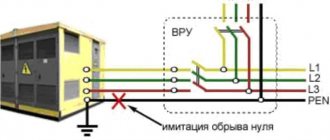
Connection diagram for Energomera CE 102 counter
Meter connection diagram