Electrical supply for a private home
A private home is supplied with power from the common power lines of a country village - be it a village or a gardening community. Today, the vast majority of residential settlements in our country are provided with electricity. Power lines are installed in such a way that the supply to each house is accessible. As a rule, near each site there is one or even several power line poles.
Powering each house from the power line is carried out by employees of the electricity supply organization - from the pole to the electric meter. Further arrangement of the power supply system is the responsibility of the owner.
To the uninitiated person, conducting electric current from the meter to every light bulb and socket in the house seems like an intractable task. It’s clear that installation of the electrical network should be carried out by professionals, but the owners should also have an understanding of this work. After all, they will have to operate the power grid. It would be nice to be able to control electrical installation work - at least within the framework of general concepts about electrical networks in a private home. This article is dedicated to getting to know these basic concepts.
Features of electrification of a summer cottage on SNT lands
From January 1, 2022, the rules for technological connection to electrical networks of plots located on the lands of horticultural non-profit partnerships (SNT) have changed. In accordance with the new rules, owners of country houses located on SNT lands cannot contact network organizations directly regarding connection. This right is granted only to the chairman of this partnership. The most interesting thing is that it does not matter whether the owner of the country house is a member of a gardening partnership. The main criterion is that his house is located on the territory of SNT.
Connected power standards remain the same as for owners of private houses. However, the nuance is the following. Typically, the electrification of a partnership is carried out en masse, that is, the board submits an application to the network company to connect the whole array. As a result, SNT is powered from a high voltage line (10 kV) and the partnership is obligated to install, at its own expense, a step-down transformer, which naturally becomes the property of the partnership. Therefore, the owner of a country house, who is not a member of the partnership, is forced to resolve all issues of his connection with the chairman of the SNT. Due to this circumstance, a number of unforeseen problems may arise, which will not be easy to solve legally.
The Importance of Electrical Network Planning
As in any business, when laying electrical networks, first of all, you cannot do without a detailed plan. First of all, this is accounting for all consumers (light bulbs, washing machines, refrigerators, etc.). Secondly, a graphical display of the electrical wiring system from source to consumer.
All stages of installing electrical networks are based on the electrical connection diagram. In general, this is a drawing that clearly shows:
- Power supply units from the input line
- Short circuit protection devices
- Distribution boxes where power lines branch off to certain premises and consumers
- Location of power lines - that is, wires
- Places where sockets for consumers are installed
The plan diagram must necessarily include information about the power of consumers, the parameters of fuses, the parameters of electrical wires and similar information.
Only having the connection diagram in hand can you begin work. A haphazard installation of wires will certainly lead to errors, and errors in working with electricity are a direct threat to the safety of life and home.
If the house was built according to an individual project, then the connection diagrams should be drawn up specifically for this house. If a standard project is used, the electrical connection diagram can also be standard.
Obtaining an energy supply contract
According to clause 72 of the “Basic Provisions for the Functioning of Retail Electricity Markets”, which were approved by Decree of the Government of the Russian Federation dated May 4, 2012 No. 442, the fulfillment by the electricity supplier of its obligations to the consumer for the supply of electricity does not depend on the existence of an agreement drawn up on paper.
In fact, the contract is considered concluded if the consumer is connected to the electrical network in the manner prescribed by law and consumes electricity. In this case, the start date of the period for which the consumer paid the electricity bill is the start date of the contract.
If the consumer decides to formalize the contract on paper, then he should contact the organization supplying electricity with an application and attached documents, namely:
- copy of passport;
- documents confirming ownership;
- act on technological connection;
- an act on the admission to operation of metering devices or other documents confirming the fact of admission to operation of metering devices (if there are metering devices).
The agreement must be drawn up by the electricity supplier within 30 days from the date the consumer submits the relevant request.
External electrical connection
Although the connection from the power line to the building is the responsibility of the electricians in your village, you live in the house, and this work also needs to be monitored, as well as providing the electricians with everything necessary for installing the wiring. Moreover, there may be several connection options, and it is up to you to decide.
Here are a few notes on this stage of work.
Wiring can be carried out both by air - from the pole to the house, and underground. The wire from the power pole to the house should not sag more than 3.5 meters from the ground. It should not touch tree branches, wooden parts of the house, or any other protruding parts. If the distance is more than ... meters from the pole to the entrance node to the house, you need to install an additional support for the wires.
For the input cable, wires with a minimum cross-section of 16mm2 are used. It can be two-core (using a voltage of 220V) and four-core (using a voltage of 380V). NYM, VVGng, VVG and PUNP wires meet all operating requirements (safety, minimal losses and durability).
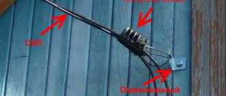
Wires extending from a power line pole must be in a protective sheath. In order to keep the wires from breaking, they are attached to a support rod. A rod in the form of a thick wire should have good tension, but the electrical wire, on the contrary, should not be fastened under tension.
Wires are introduced into the house through a hole carefully insulated with non-flammable material. The wires must be threaded through a protective casing, such as a plastic or metal pipe.
Rules for external connection of a house
Inside the house, the wires go to the electric meter, which records the electricity consumed, and from the meter to the distribution panel.
How much does it cost to install electricity?
There is a basic cost for connecting electricity, which is 550 rubles, however, to connect according to this tariff, the following conditions must be met:
- the amount of power required is no more than 15 kW;
- the nearest power transmission line of the required voltage is located at a distance of no more than 300 m for cities and urban settlements and no more than 500 m for rural settlements;
- one source of supply required;
- Electricity consumption will not be for production activities.
In other cases, the cost of connecting electricity will be determined according to established tariffs, which are regulated by local executive authorities.
The cost of connecting electricity can be 5-500 thousand rubles, depending on:
- required power;
- number of supply sources;
- distance from the site to the nearest pole;
- cost and nature of specifications.
IMPORTANT! Despite the possible monetary costs, it is necessary to connect to electricity according to all the rules, in accordance with the current legislation of the Russian Federation. If an unscrupulous consumer is connected to the power line without authorization, he or she faces high fines and penalties, including criminal liability!
Distribution panel
It is the distribution panel that is, as it were, the “brain” of the entire power supply system of the house. It is a metal box with built-in nodes from which wires extend to one or another area of the house. All components in the box are mounted so as not to touch each other.
The main elements of the distribution panel are protective fuses. They are mounted at the common entrance to the panel and for each group of consumers. Modern fuses have replaced traditional electrical plugs, where a network break in the event of a short circuit occurred after the melting of the fusible inserts included in the plugs. Today, this role is played by automatic fuses, or simply by automatic circuit breakers, where the network breaks when the temperature rises critically thanks to built-in sensors. Each machine is designed for a certain power of current consumers.
The most powerful machine is placed at the general entrance. It allows you to turn off the entire system. If it is necessary to partially disconnect consumers - for example, for repairs - you can turn off the corresponding circuit breaker. A short circuit in a single node therefore does not shut down the entire system.
Distribution panel
Project development
The technical specifications indicate:
- network power, including the maximum load of the energy consuming facility;
- list of electricity meters;
- the presence of a sealed box in cases of external connection.
Technical specifications are issued within thirty days. After receiving them, it is necessary to draw up a project and purchase electrical equipment that corresponds to the document. The most commonly purchased devices are an electric meter, a switch, a machine, cables, wires and lighting fixtures. When developing a project, it is necessary to depict a diagram of external power supply and internal wiring. The design must show the types of wires and electrical devices.
Each project for supplying electricity to a site is individual.
The location of the transformer and the planned location of the future home play an important role.
More information about the wiring diagram
The output of wires from the distribution panel corresponds to the location of consumers in different rooms. Let's take a closer look at typical electrical distribution schemes in a house.
In modern homes, we use various electrical appliances that consume different amounts of electricity. The level of its consumption is expressed in the power of the electrical appliance.
The most powerful consumers in a modern home are electric stoves and sauna heaters, the most economical are light bulbs and small household appliances.
Below are the average power consumption ratings of some of the most commonly used electrical appliances, ranked from most powerful to least powerful (in watts):
- Instantaneous water heater – 5000
- Electric stove – 3000
- Automatic washing machine – 2500
- Welding machine – 2300
- Oven – 2000
- Iron – 1700
- Boiler – 1500
- Vacuum cleaner – 1500
- Heater – 1500
- Microwave oven – 1400
- Electric kettle – 1200
- Fan – 1000
- Refrigerator – 600
- Computer – 500
- TV – 300
- Light bulb – 60
Already from this small list we can see where the main consumers of electricity in our house are concentrated - in the kitchen and in the bathroom-laundry room. Naturally, it is not recommended to turn on all appliances at once, but a switched-on electric stove with a constantly running refrigerator is enough to put a significant load on the network.
It is the nodes from which the wires lead into such rooms that have the most powerful machines.
Electrical and wiring diagram
There is an electrical connection diagram, and there is a floor plan that matches the house plan.
The electrical diagram shows what types of connections are used - where the current is supplied in parallel, where in series, etc.
Electrical network diagram
For installation, you should also have a wiring diagram. In its simplest form, it should be a drawing that coincides with the plan of the entire house. It shows the location of the electrical wires and the places where the mounting units and connectors for the power supply are located.
Electrical wiring diagram
Here we see into which room the wires from the distribution board go, what brands of wires are used, how the sockets are located on the walls, etc.
Of course, the presented schemes are quite primitive. In reality, the power supply diagram can be quite complex. The project usually combines electrical and wiring diagrams.
Transmission of electricity through air
Overhead electrical connection is an inexpensive and effective solution. The cable is laid from the nearest power line support to the house through the air. The live wire runs through a pipe that is located inside the hole in the wall and is connected to the indoor switchgear or electric meter.
The current-carrying cable can also be connected to an external meter and voltage stabilizer. The output wires are introduced into the house through a pipe. External electricity meters are placed in special sealed housings for protection.
Power distribution across premises
As we have already mentioned, the most energy-intensive rooms can be considered
- A kitchen where a good housewife uses a lot of electrical appliances...
- Bathroom and laundry room with washing machine and electric heater
- Boiler room, where the heaters are heated during electric heating of the house
Can be quite energy intensive
- A workshop where a craftsman uses powerful power tools
- A living room with many lamps installed, a TV and a couple of computers on
The most economical consumers of electricity are
- Bedrooms, children's
- Bathrooms
- Utility rooms – pantry, dressing room, corridor
- Attic and basement, where the owner looks relatively rarely
Obviously, for each group of premises a machine of the appropriate power is installed.
Electrical Security
Ensuring the safety of using electricity is perhaps a more important task than even the electricity supply itself. The danger of electricity lies in its current-damaging ability in relation to humans and in the fire hazard - due to the extreme heating of the wires during a short circuit.
This topic is quite extensive. As for the power supply circuit, the main thing in its design is to ensure the safe operation of the electrical network.
Particular attention should be paid to the compliance of the mounted machines with those indicated on the diagram. The power of the machines must be carefully calculated taking into account all the loads on the network and each of its nodes.
With regard to human safety, the wiring diagram provides for a number of measures:
- Presence of electrical insulation on all live parts
- Correct placement of sockets
- Grounding of all necessary elements
- Inaccessibility of most electrical components for accidental contact
- Increased network protection in children's rooms
- Application of special measures for protection in wet areas
8. Installation of the electrical network according to the connection diagram
Electrical installation must be carried out strictly according to the diagram and using the materials specified in it. Under no circumstances should you install machines that do not comply with the design. It is impossible to arbitrarily underestimate the cross-section of wires. You cannot be careless about the connection points of the wires.
Often, would-be craftsmen simply twist two or more wires, not caring that a loose connection is where the wires overheat or spark. It is unacceptable to twist wires made of different metals, for example, aluminum and copper. All connections must be made in special junction boxes.
Wiring on bends is only possible at right angles, otherwise it will be impossible to determine where the hidden wire is located if you suddenly have to drill into the wall.
Laying of wires must be strictly horizontal or vertical
There are many such rules, we will talk about them in more detail in other articles.
Methods for connecting enterprises to the power grid
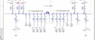
It is necessary to distinguish between two fundamental cases of connecting an enterprise to the power system: to a substation (or the main switchgear of a thermal power plant for generator voltage) and to a power transmission line (PTL). Connection to the substation is carried out through switch Q according to one of the diagrams shown in Fig. 3.1.
The most common schemes are 7 and 2. With three or more bus systems (sections), a more reliable power supply to the consumer is possible: switch Q, after its prompt shutdown, is connected to the required section through a disconnector. If there is a bypass bus system (diagram 5), when Q is turned off, the consumer can be powered through the bypass switch Qly intended for intra-station switching.
The connection of an enterprise to a power transmission line is determined by the configuration (topology) of the electrical network, which depends on geographical conditions, density and distribution of electrical loads. Possible main options for connection schemes are presented in Fig. 3.2. A radial single or double line can, by making a ring, be connected to the same power source (PS). Nodal circuits are possible, in which there are more than two PIs and more than three lines, and multi-circuit circuits, which include several nodal points.
The diagram shown in Fig. 3.2, a, is rarely used and is found to power consumers of category III, enterprises in areas with low load, remote or at the beginning of construction. According to this scheme, it is possible to power the consumer from another power source, which actually means a transition to the circuits presented in Fig. 3.2, d, f. The diagram shown in Fig. 3.2, b, the most common, the number of connections (saps) to one line should not be more than three. If a substation is fed radially along one or two lines without taps, then it is called a dead-end substation.
The substations shown in Fig. 3.2, a...g, are called branch lines , and in Fig. 3.2, d, f - passable . If power flows between individual points of the network through high voltage (HV) buses, then the substation is called transit.
When deciding on the construction of one double-circuit overhead line or two overhead lines on different supports, an increase in reliability is accompanied by large capital costs (investments) and alienation of land. The reliability of power supply from lines on different supports, but along one route, increases slightly, and major accidents caused by climatic conditions damage lines regardless of their design. Therefore, the construction of single-circuit power lines requires justification, with the exception of power supply to main pipelines and electrified railways. In the scheme, both lines are loaded evenly, which minimizes losses, the levels of short circuit currents do not increase, and it is possible to connect 5UR substations according to the simplest scheme.
The diagrams presented in Fig. 3.2, v...e, is used in networks with a voltage of 220-110 kV power systems with low and medium load power, in industrial enterprises with several power sources and the need to ensure high reliability of the power supply circuit.
The average substation RP2, shown in Fig. 3.2, hp, is provided as a consumer of a special group of category I. For this scheme, it is necessary to take into account uneconomical flow distribution, a higher level of short-circuit currents, and a greater complexity of operational switching.
Taking into account the features of a specific house in the diagram
Among other things, the connection diagram must take into account the characteristics of the materials from which the house is built. Under no circumstances should a plan diagram for a brick house be used in a wooden frame house without any modifications. These materials have different fire resistance and different electrical conductivity. It is necessary to take into account what material is located close to electrical components - metal, wood, plastic or wet tiles - and provide sufficient insulation and maintain the required distance from live parts. All this must be included in the electrical connection diagram.
Preparation of documents and submission of an application for technological connection
An important condition is that you should choose a network company from the closest ones. Before contacting a network company to apply for a technological connection and conclude an agreement, you must prepare the following documents:
- Application for technological connection, a sample and form for filling out which you can find on the network company’s website or pick up at its office;
- Copies of documents confirming ownership of the plot (house);
- If there is construction going on at the connected site, then a list of equipment that consumes energy is required. If there is already a residential building on the site, then a list of household appliances that are the main energy consumers is required;
- Site plan;
- Applicant's passport and TIN certificate.
IMPORTANT! An application for supplying electricity to a site (house) must be filled out in two copies, one of which remains with the network company, the other with the applicant.
Sample application for technological connection
An application from an individual for connection to one source of power supply to power receiving devices with a maximum power of up to 15 kW is shown below.
You can also apply.