In the dictionary Dictionary of foreign words
y, w.
1. A drawing showing the structure of something. or the relationship of parts of something. S. device. S. railway tracks. Circuit - related to the circuit, circuits.||Cf. GRAPH" title='GRAPHIC, GRAPH is, what is GRAPHIC, GRAPHIC interpretation'>GRAPH I, DIAGRAM" title='CHART, DIAGRAM is, what is DIAGRAM, DIAGRAM interpretation'>DIAGRAM, KROKI" title='CHART, KROKI is , what is KROKI, KROKI interpretation'>KROKI, PLAN" title='PLAN, PLAN is, what is PLAN, PLAN interpretation'>PLAN.
2. Presentation, description, depiction of something in its main features. General s. events.
3. An abstract and simplified image of something, a general ready-made formula. The play does not have characters, but patterns.
Share the meaning of the word:
Scheme
The meaning of the word Scheme according to Efremova: Scheme - 1. A drawing depicting a system, device of something. or the relationship of parts of something. 2. Presentation, description of something. in general terms, without details. // General plan for building, organizing something. // transfer Something that is created in a simplified and abstract form, as if from a stencil.
The meaning of the word Scheme according to Ozhegov: Scheme - Presentation, description, image of something in its main features
Scheme
A set of interconnected parts of some device, instrument, unit, as well as a drawing explaining the principles of operation of such a device
Scheme in the Encyclopedic Dictionary: Scheme - (from the Greek schema - external appearance - form), 1) a drawing in which the component parts of a product or installation and connections or connections between them are shown in verbal graphic symbols. 2) Description, presentation of something in general, main features.
The meaning of the word Scheme according to Ushakov’s dictionary: SCHEME
diagrams, g.
(Greek schema-image, view). 1. Drawing showing the system. device of something or the relationship of parts of something. circuit
.
circuit
. Engine diagram. Construction diagram. 2. Statement, description or image of something. in basic, main, general terms. Outline of the novel. Outline of the report. || trans. Stencil sample, shape (neglected). Think in ready-made schemes.
Definition of the word "Scheme" according to TSB: Scheme
- Scheme (from the Greek schéma - appearance, form, outline, outline) 1) image, description, presentation of something in general, main features.
2) A drawing that usually reproduces, using symbols and without respect to scale, the main idea of any device, structure, etc. See also Diagram in design documentation. Diagram - in design documentation, a document on which the component parts of a product (or installation) and the connections or connections between them are shown using conventional graphic symbols.
S. are carried out, as a rule, without taking into account the scale and actual spatial arrangement of the component parts of the product. Depending on the type of product elements and the type of connections between them, systems are divided into electrical, pneumatic, hydraulic, kinematic, and combined; In accordance with the purpose, systems are distinguished: structural, functional, fundamental, connections, connections, general, location. A structural diagram (block diagram) defines the main functional parts of a product (installation), their purpose and interconnections; it is developed during the design (construction) of a product, earlier than of other types, and is used in studying the structure of the product and the program of its operation, as well as during its operation. Functional S. reveals the processes occurring in the product and its individual parts; used when studying the functionality of products, as well as when setting up, adjusting, monitoring and repairing them. Fundamental S. determines the complete composition of the elements of a product and the connections between them and, as a rule, gives a detailed understanding of the principle of operation of the product; serves as the basis for the development of other design documents, for example electrical installation drawings, specifications. C. connections (internal and external) displays the connections of the component parts of the product, methods of laying, fastening or connecting wires, cables or pipelines, as well as the places of their connection or entry. Connections C shows the external connections of the product; these S. are used during installation and operation of complexes. General system determines the components of a complex (complex product) and their connections to each other at the site of operation; is intended primarily for general familiarization with the complexes. The S. location shows the relative placement (location) of the components of the installation or complex. In the USSR, the procedure for registering S. is established by GOSTs. V. N. Kvasnitsky. Grasp Scheme Schaefer And Bell Children-Parents Relationship Scheme
Links
| Electrical diagram on Wikimedia Commons |
- [elektrik-master.ru/index.php?m=0&s=113 Examples of electrical circuits]
- [electricalschool.info/main/electroshemy/557-pravila-chtenija-jelektricheskikh-skhem.html Rules for reading electrical circuits and drawings]
- [protect.gost.ru/v.aspx?control=7&id=174186 GOST 2.701-2008. ESKD. Scheme. Types and types. General requirements for implementation]
- [protect.gost.ru/document.aspx?control=7&id=178579 GOST 2.702-2011 Unified system of design documentation. Rules for executing electrical circuits]
| : Incorrect or missing image | To improve this article it is desirable:
|
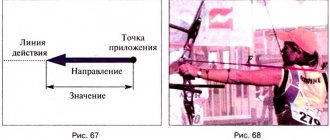
Members of the sentence: where to start?
The first place to start is to define what a proposal is. These are several words that are connected logically and intonationally. Most importantly, there is a grammatical basis, which consists of a subject and a predicate. The first main term denotes an object or person who performs some action. The predicate will tell about it.
You will be interested: Minsk Energy College - a place to obtain a sought-after profession
Another important point is the definition of the word with which the sentence begins, as well as the total number of words. For example, “Mom is reading a book.” The first word in the sentence is “mother”, and there are three words in total. Now we need to find the grammatical basis. The first question is: “Who?” This means we are talking about an animate object. Second question: “What does it do?” It refers to the verb. It remains to define the word “book”, which is a minor member of the sentence, an addition.
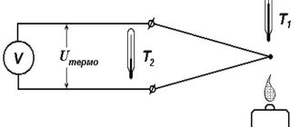
Transistor characteristics.
The first implementation of the transistor (1948) ushered in an era of electronics in which miniaturization, efficiency, and reliability of devices far exceeded previously achieved limits. Among the many developed semiconductor devices, two are most often used in modern microelectronics: the bipolar junction transistor (BJT) and the field-effect transistor (FET). Traditionally, electronic devices are usually classified by the number of pins. A diode has two terminals, while a triode (BJT and FET are triodes) has three. Tetrodes and pentodes have four and five terminals, respectively.
A bipolar transistor contains junctions between semiconductor material p
n
semiconductor material (where conductivity is provided by negative charge carriers - electrons).
The metallurgical transition between these materials - a pn
junction - forms a device called a
pn
junction diode.
All diodes give a characteristic at their terminals of the type shown in Fig. 1, b
.
In Fig. 1, a
shows the diode symbol used in the drawings and a test circuit that allows you to take its current-voltage characteristic.
The diode characteristic has a region of low resistance increase (steep branch), in which a small increase in the applied voltage gives a large increase in current through the diode, but at the same time there is also a region of high resistance increase, where the diode passes a small current regardless of the voltage applied to it. These regions are called the regions of forward and reverse current flow, respectively. Typical current values for non-power diodes can be 10 mA forward and 0.1 µA reverse. If the voltage applied in the reverse direction is made large enough, diode breakdown may occur. This type of breakdown, however, can be used to create a diode voltage regulator known as a semiconductor zener diode. Such diodes are available for a wide range of breakdown-stabilized rated voltages.
A junction diode used for higher power applications, such as converting AC to DC, is commonly called a rectifier.
Basically, a bipolar transistor is a region of semiconductor material p
- or
n
-type, which forms junctions with regions of semiconductor material having conductivity of the opposite type.
Thus, there are bipolar transistors of both n
-
p
-
n
- and
p
-
n
-
p
-types.
Various structures are used to optimize transistor performance. In all cases, the common region is called the base, and the junctions are called emitter-base (emitter) and collector-base (collector) junctions. The three external pins are named base, emitter and collector and are designated b
,
e
and
c
(Fig. 2).
The electrical characteristics of the emitter-base and collector-base junctions, taken separately, are the same as those of a diode; Therefore, a transistor is often said to be two diodes connected back to back. For proper operation of a transistor, the bias voltage for it is chosen so that the emitter junction is forward biased and the collector junction is reverse biased. In Fig. 2 shows the bias voltage Ve
and
Vc
and the directions of the currents they create.
Note that a pn
junction is forward biased when
the p
region is positive with respect to
the n
region.
A convenient way to present the current-voltage characteristics of a transistor is to use a graph with a family of curves. These curves can be useful in designing circuits for large-signal operation or, more commonly, in developing small-signal models that can then be refined using circuit design techniques. When constructing the characteristics of a transistor, several options are possible for choosing the abscissa, ordinate, and parameter. One of the options leads to a family of curves for a switching circuit with a “common base” (Fig. 3).
The curves presented in Fig. 3, well illustrate the operation of the transistor. It is important to pay attention to the following points. Except for the influence of collector voltage, the input characteristics shown in Fig. 3, a
, essentially the same as that of a forward biased diode;
but this is only true until a point is reached where the collector-base junction becomes reverse biased. The output characteristics (Fig. 3, b
) show that the collector current is only slightly less than the emitter current and is practically independent of the collector voltage when the collector-base junction is reverse biased. Note that the output characteristics are essentially the same as the reverse-biased junction, but shifted by the amount of emitter current. The fact that a change in emitter current does not cause the same change in collector current shows that there is no gain being achieved here. However, since a high-resistance resistor can be used as a load, the transistor in this circuit can serve to transfer current from a low-resistance source to a high-resistance load, thereby providing significant power amplification. Other transistor circuits can provide current and voltage amplification.
The transistor, as already mentioned, has three electrodes. Selecting one of the electrodes as a common one for the input connected to the source and the output to the load gives, in principle, six basic amplifier circuits. Of these, only three are widely used: a common-base circuit with an emitter as an input and a collector as an output; a common emitter circuit, where the base serves as the input and the collector as the output; a common collector circuit where the base serves as the input and the emitter serves as the output. The most commonly used circuit is a common emitter.
A description of the process of creating equivalent circuit models for amplifiers of the considered configurations and obtaining mathematical expressions that give the characteristics of such circuits are beyond the scope of this article. The results of the corresponding calculations can be briefly presented in the following form.
How to create a complex sentence diagram with multiple clauses
In order to correctly display sentences that have several subordinate clauses, a vertical diagram is used:
“We learned that a hurricane was coming that could destroy everything on the coast.” (sequential submission):
“When we were already approaching the city, Daniil squinted to get a better look at the surroundings.” (parallel submission):
“We are very glad that you came, that you are with us today, that you like it here.” (homogeneous submission):
The main purpose of this article is to help you remember school rules for the Russian language and remind you of the main points, observing which you can easily construct a diagram of any sentence.
Since you are here, you are probably a school student who needs to draw up a sentence outline. This is standard homework. The diagram is usually done as part of the syntactic parsing of a sentence, but it can also be done separately.
I suggest you take a test - answer five questions according to the sentence pattern.
[quiz-cat >Well, what did you get? And now the explanations.