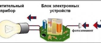
Operating principle
The diagram shows the principle of operation of the device. Photoresistor PR1 reduces its resistance to several Kohms as the illumination increases, due to which phototransistor VT2 opens, which turns on photorelay K1, and this device, in turn, will begin to transmit signals. Diode VD1 protects the circuit from self-induction. Thanks to this principle, even very weak signals can turn the light on or off.
Photo - Photo relay circuit
The main working part is a photocell, which is a gas tube in which gas ionization occurs. It has a cathode that is capable of producing electrons in proportion to the intensity of light directed towards it, and the tube is also equipped with an anode to collect electrons.
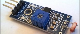
Photo – Photo relay
Whenever a negatively charged surface is placed in an atmosphere of an ionizable gas, such as mercury vapor or any inert gas, electrons are transferred to it. There, by using the Fermi-Dirac velocity theory, electrons are accelerated depending on the strength of the applied electric field.
Photo – Photo relay TDM
These electrons travel a relatively short distance before colliding with an ionizing gas atom. When an electron, which has constant kinetic energy, passes through an ionizing substance, it disturbs the atoms it encounters. Also, its trajectory of action may change periodically. If the material is gaseous, the resulting fragments or ions may move away from each other. But if electrons are knocked out of atoms, then they move in one direction, and the residual positive ions move in the opposite direction. The output of the ionization type or photocell depends on the number of electrons at the anode.
It is the movement of electrical particles in a certain sequence that causes the device to switch. It must be said that this is especially convenient for devices with a motion sensor Finder, Legrand.
Operating principle of photo relay
To automatically control the lamps based on the illumination of the workplace and the Day-Night factor, a special light-sensitive sensor is used. It changes its electrical characteristics depending on the intensity of light falling on it.
There is a regulator to adjust the response level. After it, the signal from the sensitive element is amplified to the required value and fed to the relay winding of an electromechanical or static design.
In this way, depending on day or night lighting, the light sensor controls the voltage supply to the relay coil. And the last one connects or disconnects the power supply phase of the network to the lamp through its contact.
How does the photo sensor work?
To control the amount of light flux, various electronic components are used, including:
- photoresistors;
- photodiodes;
- phototransistors;
- photothyristov;
- phototriacs.
How does a photoresistor light sensor work?
The semiconductor layer, irradiated by electromagnetic waves of the optical spectrum, changes its electrical resistance.
A stabilized voltage source is applied to it, under the influence of which a current begins to flow in a closed circuit, calculated according to Ohm’s law. Its value depends on the nature of the change in the resistance of the semiconductor layer of the light sensor.
As the luminous flux increases, the electric current increases, and as it decreases, it decreases. All that remains is to determine the boundary states at which it is necessary to turn on the lighting source in the operating state or turn it off.
How does a photodiode light sensor work?
A photosensitive element of this type converts the energy of electromagnetic oscillations in the visible spectrum into electric current.
Its value also depends on the strength of the irradiation, which makes it possible to set the limits for the operation of the photo relay.
Photodiode light sensors can be connected to work in circuits with:
- powered by an external, additional voltage source;
- or do without using it.
How does a phototransistor light sensor work?
The operating principles used for the two previous cases are also followed here. Phototransistors operate in the same way as their bipolar or field-effect counterparts. Their characteristics are affected by the intensity of irradiation with light flux.
Having determined this pattern, the boundaries of the operating settings for the final photo relay circuit are set. In the same way, light sensors are created using photothyristors and phototriacs.
How does the electrical circuit of a light sensor on a photo relay work?
As an example, consider the simplest device with a photosensitive element based on photoresistor PR1, which has a resistance of several megaohms in complete darkness.
Under the influence of a stream of light it will drop to several kiloohms. This value is enough to open the first transistor VT1, when the collector current begins to flow through it, opening the second stage on the transistor VT2.
This arm includes the winding of an ordinary electromagnetic relay K1. She will throw her own armature to the second position and switch her contact K1.1, which controls the operation of the lamp.
When the relay is disconnected from the circuit, its winding generates a self-inductive emf. To limit it, a diode VD1 is installed. Substring resistor R1 is used as a regulator of the light sensor response setting. In some cases, you can refuse it altogether.
By using two transistors operating in series, the sensitivity of such a circuit is achieved to a very high value when a weak light signal incident on the surface of the photoresistor switches the output relay and controls the lamp automatically.
This scheme is quite universal. It allows you to use different brands of transistors, electromagnetic relays and set different voltages for them. The larger its value, the higher the sensitivity of the light sensor.
Factory photo relay modules for twilight switches have a more complex circuit structure, a more powerful output contact, but basically they repeat the same principles.
In homemade designs for automatic light control, the circuit described in the article here has proven itself well. It is easy to repeat with your own hands for those who know how and love to work with a soldering iron.
Motion sensor and light sensor
Having finished disassembling the connection and connection of the photo relay for street lighting, we will move to the premises under the roof. A similar system can also be found here. In essence, other than the vastness of the space compared to the outer limits, there are no differences. At night, as on the street, nothing is visible indoors. And here we also need an illumination system to disperse the darkness during periods of darkness. But not every prudent owner is willing to pay extra money for electricity that is wasted senselessly most of the time. After all, the need for light, although it arises occasionally at night, does not last throughout its entire period. This is where the connection of several components will come to the rescue: a light and motion sensor. That is, the system itself will only work at night and precisely at the time when someone moves within the range of the sensors. At the moment both factors are determined, a command will be given to the lamp to turn on. The main thing is not to forget to set the photo relay to the current level of illumination of the space and the motion detector to the desired sensitivity.
Connection diagram of the motion detector and light sensor to the lamps:
A quick note regarding the motion detector. It must be either infrared or ultrasonic. The reason is simple - the optical one, while the light is off, will not “see” the movement of the object in the touch field, and therefore will not give a command to activate the lamps.
Connecting a photo relay
The connection diagram for photo relays for street lighting comes in two types: with two wires or a number of wires that is a multiple of two when connecting a number of lamps or lanterns directly to the relay, or with three terminals.
All modifications of relays with three terminals according to the international standard have three multi-colored wires. To connect the photo relay to the lighting, it is necessary to make wire connections according to the drawing. This usually happens as follows when the relay has 3 wires of different colors:
- Brown. Connects to one of the AC wires directly in the relay wiring box;
- Blue. It is a “zero” wire, connected to the neutral terminal in the wiring box, from which a wire goes to the lighting fixture;
- Red. The wire from the light relay is connected to the connector in the installation box, from which the phase is supplied to the light device.
With a two-wire circuit, the phase with the neutral wire is connected to the two corresponding contacts of the relay box, and the lighting devices to the other two; more of them can be connected in parallel.
There are modifications of photo relays used for operation in electrical networks with a grounding bus; for this purpose, the mounting box is equipped with an additional terminal for connecting the grounding wire (green).
A diagram of how to connect a photo relay is always drawn on the device body itself and is indicated in the technical data sheet, so it is almost impossible to make a mistake when connecting.
Advantages of photo relay
Unlike contact-type control components, for example, electromechanical or induction relays, the described devices are distinguished by their durability. In addition, these devices based on field-effect transistors (the so-called MOSFET transistors) heat up less, and therefore can be used in long-term operating control circuits, for example, in photo relays for street lighting.
Metal Oxide Field Gate Transistor
The use of MOS transistors as a signal output device allows them to be used in solid-state relay circuits that operate on both alternating and direct current.
Subsequent comparison of the effectiveness of the product with other types of tracking devices for similar purposes can be performed using the following parameters:
- Minimum installation space required (less than relays with moving parts).
- Reliability (higher, since there are no moving contacts that wear out due to friction and electrical erosion).
- Energy consumption (less due to the absence of auxiliary components; battery-powered operation is possible).
- The switching intensity does not depend on the number of switchings, because there is no need for transmitting devices.
Photo relays are also advantageously characterized by the absence of noise during operation, high speed of switching control modes, and the absence of audible clicks during operation.
The compactness of a typical photo relay circuit for street lighting is illustrated in the figure:
How to connect a device to a street lamp: diagrams and principles
When connecting a simple device, you need to familiarize yourself with its design. The main element is a photodiode, which can be located outside or inside the housing. In the first case, the sensor is mounted outdoors, and the electronic unit is connected to an electrical panel indoors. If the sensitive part is located internally, the device is mounted outdoors.
The device is small in size and easy to mount
Knowledge of the design features of the device allows you to connect it to the flashlight as efficiently as possible
Therefore, it is important to determine the type of photo relay, purchase a high-quality device, select a circuit, and then begin connecting the sensor
Photo relay on the diagram
The correct connection diagram greatly facilitates self-installation of the device. In the electrical diagram, the photodiode is presented in the form of a conventional graphic symbol, which is a triangle on the axis of symmetry with arrows directed from top to bottom. On simple diagrams, the device can be designated as a circle or rectangle with the inscription “FR”.
The arrows in the diagram symbolize the reflection of light
Connection
The bracket with the device is mounted in a shaded place. Tree foliage, canopies, and precipitation should not affect the operation of the device. After determining the location, you need to find out the number of lamps for which control is required. One photo relay is mounted per light source. If you use a large number of flashlights, then it is best to use a controller. It receives a signal from a photosensor and allows you to control several lamps simultaneously.
The connection diagram for one lamp is very simple
The design of the device may include terminals, which simplifies connection. They are necessary for clamping wires. The cable of each color is connected to the corresponding wire of the lamp and power circuit. If there are no terminals, then a junction box should be installed. The device body must be protected from moisture and precipitation. Well-known manufacturers indicate on the packaging or in the instructions the connection diagram of the element.
Where to put
The installation location is selected so that the photocell is not exposed to light from a lamp, window, or advertising board. When the house is located near the roadway, the light from the lights of passing cars should not be directed at the device. The choice of location is limited by height requirements - 1.8-2 meters from the ground (if installed higher, a stool/chair or ladder/step-ladder will be required for adjustment).
Solving this problem is made easier by using some tricks. The photo sensor can be protected with a piece of black plastic pipe of the appropriate diameter, 15-20 cm long. The cutting angle is 30-45° from the pillar or wall. If there is only one spotlight, the photo relay is placed on the other side of the pole. The parameters are adjusted more accurately if the sensor is placed on the west or east side.
Microprocessor photo relay
Modern technologies have also affected photo relays. Devices based on microcontrollers are increasingly being used, which allow not only determining the presence of light flux, but also combining many other functions. Moreover, the expansion does not require significant changes in the hardware component; it is enough to modify the internal program.
A microcontroller is a small computer, initially focused on controlling devices depending on external factors and an algorithm. In addition, its capabilities are quite sufficient for joining a common digital network that unites groups of equipment of various types.
It is also worth mentioning industrial samples of photo relays equipped with a “smart” part. But their functionality is usually limited by the manufacturer. Therefore, it is better to consider another system. For example, Arduino. Its capabilities are quite sufficient to control the light, turn off the line day and night, send messages about the current mode in use or signal problems in the performance of the lamp.
On the hardware side, everything that does not directly relate to the control functions is assigned to additionally connected “shields” to the Arduino. In the above diagram, the latter will refer to the clock, the light sensor and the relay itself. The issue of sending the status to the final owner is resolved using the GSM communication module, which will send SMS about the current operating mode of the system.
The design concept is quite simple:
There is a note regarding the above assembly
Please note that the relay module has external power supply. This is done in order to avoid current surges, since the shield takes a lot of electricity from the common line and can cause a voltage “dip” when switching
Separate power supply is also recommended for SIM800L (in the diagram above it is connected directly to the Arduino itself). Also, the GSM communication module is quite a consuming element - it needs to generate a certain power to connect to a cell tower, and it can only take energy for this purpose from the supply line.
As for the software part, anyone familiar with programming Arduino microcontrollers can write the appropriate algorithm. Moreover, there are many codes on the Internet.
Despite the functional simplicity of the photo relay, it has enough niches for application. Moreover, small capabilities are expanded by adding new ones due to slight complication of the circuit and the use of microcontrollers.
Repair of photo relay IEK FR-602.
We first disassemble the housing and repair the photo relay. The relay is activated depending on the light level, and the lighting should turn on. Our photo relay does not work. Inside the case there is a diagram in the photo:
I soldered two wires myself and found the faulty element. This is a 24 volt zener diode. It was punched in both directions. This can be checked with a multitester.
When I unsoldered the zener diode, I began to understand the circuit. I tried to turn on a light bulb without a zener diode. There is a sensor there that reacts to light. We cover it, the light comes on. Further, when we open the light sensor, nothing happens, since the zener diode is broken and the photo relay does not work. We will change the zener diode. Since the voltage increased at the point of the zener diode, where there is a 100 uF capacitor at 50 volts. I also decided to replace this capacitor. The voltage increased by more than 50 volts. If it is dark, then the voltage drops at this point to 18 volts, and if it is light, then it rises to 80-90 volts. The zener diode was supposed to stabilize this voltage. Therefore, the capacitor heated up and swelled.
To avoid any surprises in the future, we will solder everything together. Solder the capacitor, do not confuse the polarity. The minus is indicated by white shading. We solder in a new capacitor. The cost of repairing a photo relay is currently 10 rubles. Therefore, it is worth repairing. The capacitor on which the voltage rose above the rated voltage has been replaced. Next, let's test the new zener diode to make sure it's working properly. It opens in one direction and has resistance. It does not open in the other direction, that is, it rings like a diode. It's 24 volt.
In the diagram, the zener diode is designated as Z1. A slightly burnt zener diode pad is visible on the board. He was warming himself. The zener diode has a black stripe. Solder it to the white line on the board. Instead of a load, we have a light bulb connected to check the functionality of the photo relay. And also, let's see what the voltage is at the zener diode point in low light and in good light. We bite off the legs that are not needed. There is a plug connected that plugs into the socket. Check that the wires are soldered correctly. Set the voltage to 200 volts on the multimeter. We close the sensor from light, the load (light bulb) turns on. We open the sensor, it becomes light, the lamp turns off. The scheme works.
Now let's check with a tester what is happening with the voltage. When the sensor is open, the multitester shows 26 volts. When the sensor is closed, the voltage drops to zero, the lamp turns on, the voltage is 18 volts. When there is light, the voltage rises again, reaches 26 volts, and the zener diode is triggered. All that remains is to assemble all the parts into the housing, and the repair of the photo relay is completed. There is a diagram of a photo relay on the Internet.
Lighting control using a time relay
Time relays are widely used in automation circuits, including lighting control.
Time relays can be divided into two large groups:
- Programmable time relays - the relay closes and opens its contacts in accordance with a given program;
- Timers - a time relay closes and opens its contacts for a specified time after applying a control signal.
Programmable time relays and timers can be electronic or electromechanical.
Programmable time relays can be with daily (the same program is repeated every day), weekly (the same program is repeated every week) and annual cycle (the program is set for a year).
Basic circuit and operating principle
Let's consider the operation of a lighting control circuit based on a programmable time relay operating according to one daily program.
Lighting control using a time relay. Basic scheme
Let's say the lighting should be turned on every day from 9:00 to 18:00. We set the current time in the time relay and set a program according to which at 9:00 the relay should close its contacts for a period of 9 hours. Every day, when 9:00 comes, the KT1 time relay closes its contacts, the power circuit is closed and the lighting is turned on. After 9 hours, the program ends and the relay opens its contacts - the lighting turns off.
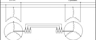
Schemes for controlling lighting of several lines using a time relay
To control several lines according to one program, time relays are used in combination with contactors. Contactors turn the power on and off, and a time relay controls their operation.
Lighting control using time relays and contactors
Power is supplied to the coils of contactors 1KM1, 2KM1, 3KM1 through a three-position switch SA1 with a neutral position:
- In the “Manual” position, power is directly supplied to the coils of the KM contactors and they close their pairs of contacts, the lighting is turned on in accordance with the specified program;
- In position “0” the power supply circuit of the contactor coils is broken and the lighting is turned off;
- In the “Automatic” position, power is supplied to the contactor coils through the contacts of the KT1 time relay. Turning the lighting on and off is controlled by a time relay, closing and opening its contacts in accordance with a given program.
If necessary, you can supplement the circuit with an HL signal lamp connected parallel to the contactor coils, which will inform you that the lighting is turned on.
Lighting control using time relays for staircases
To save energy and control lighting from several places, use a time relay from a group of timers. This type of relay closes or opens its contacts after a control signal is applied to their coil; the closing or opening of the contacts occurs with a specified time delay.
This type of time relay is mainly used in motor control circuits and ATS (automatic transfer switch) circuits, but is also used to control lighting. For example, to control the lighting of staircases.
Let's consider the use and operation of a time relay to solve this problem:
- At the initial moment of time, the KT1 relay contacts are open, the lighting is turned off. Buttons SB1, SB2... are installed on each floor of the staircase and connected in parallel to the control contacts of the KT1 time relay.
- When you press any of the SB buttons, a control signal is sent to the coil of the time relay KT1, it closes its contacts, the lighting turns on, and the time relay begins counting.
- After a specified time, relay KT1 opens its contacts and the lighting turns off.
- If, when the relay contacts are closed (i.e. before the set time has expired), a new control signal is received, then the time countdown begins anew.
Staircase lighting control using a time relay
Thus, a person entering the staircase presses the push-button switch SB and turns on the lighting. On the next floor he presses the button again, etc. After a specified time, the lighting in the staircase turns off. The shutdown delay setting is selected so that a person has enough time to walk from one pushbutton switch to another.
This circuit can also be used to control lighting in corridors. It allows you to organize the switching on of lighting from several places (as when using a pulse relay) and at the same time save energy.
Where can I use a device with automatic light control?
A photo relay can be used to turn lights on or off at different times of the day. For example, when darkness sets in, the device turns on the lighting, and at dawn it turns off. It can also be used at the entrance of an apartment building or on your own country site.
There is widespread use of an LED lamp with a photo relay, which turns the lighting on and off in autonomous mode. Such a device can be used in a “smart home”. At the same time, using a photo relay you can not only control the lighting, but also open zhaluse.ru blinds or ventilate the room. It should be noted that this device can be installed for a home security system.
How to install a photo relay
You need to use special holes to complete the installation. You just need to follow a few important rules.
- It is imperative to check what voltage the supply network operates with before installing the magnetic starter and other elements. It is necessary to have an indicator of approximately 220 V. The minimum deviation is 10 percent up or down. We also need to make sure that the protection complies with all the rules. This applies to the fuse, circuit breaker.
- Installation is prohibited if there are chemically active substances nearby. Do not place with flammable or flammable materials.
- The connection diagram suggests that the base of the device should only be at the bottom, not at the top.
- The light from the lamp being switched on should never fall on the photosensor.
Installation of photo relay
It is not difficult to install a photo relay with your own hands; it is only important to exclude the direct influence of the adjustable light source and protect the device from adverse external influences: moisture, direct sunlight, temperature changes
For industrial devices, there are a number of standards that such solutions must comply with: GOST (domestic) and IP (international). It is more difficult to ensure that a homemade photo relay is protected from environmental factors, although it is theoretically possible. But for those who want to install such a device in their yard, near their entrance or garage, it is better to first consider the solutions offered on the market - without having the necessary knowledge and experience, it will be extremely difficult to bring the photo sensor to working condition with your own hands.
Selecting a photo relay
There are devices on sale, both domestic and foreign, with a similar set of functions. When choosing a device, you should be guided by the following rules:
- The total power of the connected luminaires must correspond to the rated current load specified in the relay passport and not exceed it.
- The supply voltage and type of current (DC or AC) must correspond to the selected model.
- For outdoor installation, it is necessary to use a device with a degree of protection not lower than IP. In the case of a remote sensor, the IP for the electronic unit may be reduced if it is installed in a protected place.
- If you need flexible settings, you should choose a relay with additional functions or a professional model.
Step-by-step installation instructions
Right away I would like to move a little away from the topic and advise you to simultaneously connect a photo relay and a motion sensor for lighting. When paired, these two devices will allow you to turn on the lamp when darkness falls, only if a person appears in the detection zone. If there is no one on the site, the lights will not light up, which will significantly save energy.
The installation method depends on what protection class and type of mounting of the twilight light switch you purchased.
Today there are various manufacturing options, namely:
- with mounting on a DIN rail, on a wall or on a horizontal surface;
- outdoor or indoor use (depending on IP protection class);
- photocell built-in or external.
In the instructions, we will provide an example of installing a photo relay for street lighting with wall mounting. The connection is made at the stand for convenience, especially since this is just an example.
So, in order to connect the photo relay to the lamp yourself, you must complete the following steps:
- We turn off the power at the input panel and check the presence of current in the distribution box from which we will run the wire.
- We stretch the power wire to the installation site of the photo relay (next to the lighting fixture). We recommend that you use a three-core PVS wire to connect the twilight switch, which has proven itself to be a reliable and not too expensive conductor option.
- We strip the conductors of insulation by 10-12 mm in order to connect them to the terminals.
- We create holes in the housing for inserting the cores in order to connect the photo relay to the network and the lamp.
- To increase the tightness of the case, we attach special rubber seals in the cut holes to protect against dust and moisture getting inside. By the way, the twilight switch must be placed in such a way that the inlet holes are at the bottom, which will prevent moisture from penetrating under the cover.
- We connect the photo relay for street lighting according to the electrical diagram that we provided above. As can be seen in the photo, the input phase is connected to connector L, and the input neutral to N. A separate screw terminal with the appropriate designation is provided for grounding.
- We cut off the required length of wire to connect the photo relay to the light bulb (in reality, it could even be an LED spotlight). We also strip the insulation by 10-12 mm and connect it to terminals N' and L', respectively. The second end of the conductor is brought to the light source and connected to the terminals of the socket. If the lamp body does not conduct current, grounding does not need to be connected.
- Installation and connection are completed, let's move on to setting up the photo relay with our own hands. There is nothing complicated here; the kit includes a special black bag, which is necessary to simulate night. On the body of the light sensor you can see a regulator (signed with the abbreviation LUX), which is used to select the light intensity at which the relay will operate. If you want to save energy, set the rotary control to minimum (o). In this case, the signal to turn on will be given when it is completely dark outside. Usually the regulator is located next to the screw terminals, a little to the left and above (as shown in the photo).
- The last step of connecting the photo relay is to attach the protective cover and turn on the power on the panel. Once you do this, you can proceed to testing the device.
That's all I wanted to tell you about how to install and connect a photo relay with your own hands. We also recommend that you watch a visual video lesson, which shows in detail the entire essence of electrical installation.
Instructions for connecting a Feron photo relay
Finally, it should be said about which manufacturers of twilight switches are of the highest quality. Today it is recommended to give preference to products from companies such as Legrand, ABB, Schneider electric and IEK. By the way, the latter company has a fairly reliable model - FR-601, which has many positive reviews on the forums.
How to connect a light sensor with a photo relay to a lamp and perform installation
Using wire colors
The electrical circuit for connecting the twilight switch is assembled on the basis of a junction box, into which three wires from the electrical panel come with a cable:
- phases;
- zero;
- grounding conductor.
The photo relay itself also has three wires. They usually have the following colors:
- brown, connected to the mains power phase;
- red, which supplies phase potential to the lamp through a built-in contact when it is turned on at dusk;
- blue, connected to the working zero of the circuit.
The photo of the twilight switch shows these wires and the dimmer. When you rotate its handle, the threshold for the light sensor is set.
Installation features
The usual length of wires protruding from the photo relay body does not exceed twenty centimeters. Therefore, it is customary to install it in close proximity to the distribution box, and the lamp itself:
- carried out to some distance;
- or placed side by side as shown in the photo.
In the second method of mounting the circuit, it is necessary to take into account that the light from the switched on source lamp does not fall into the field of view of the light sensor. Otherwise, false positives will occur. To eliminate it, a timer and motion sensors are additionally used.
Their contacts are included in a serial chain between the red wire coming out of the photo relay and the socket of the lamp lamp. The operation of the motion sensor and timer is subject to the programmed algorithms of the twilight switch logic circuit.
Connecting several lamps to one photo relay
The output contacts of the final light sensor have a certain switching capacity. Their value is indicated in the technical documentation and on the body of the twilight switch in amperes. If you need to control light from several sources, you must carefully calculate the load created by them all together.
If the power of the contacts allows, then the lamps are connected in a parallel chain, as shown in the photo below.
Sometimes a situation may arise where the circuit load exceeds the permissible power of the twilight switch contacts.
In this case, it is permissible to use the same photo relay, but connect an intermediate element to its contacts - the winding of the magnetic starter, which has a lower load.
The powerful contacts of this switching device will reliably switch a chain of many lamps or one powerful spotlight, as shown in the diagram below.
You will have to select a magnetic starter based on the type of control coil and the power of the contact group.
Important technical characteristics of the light sensor
Photo relays are selected by:
- photosensor sensitivity;
- type and magnitude of supply voltage;
- power of switched contacts;
- twilight switch operating environment.
Photo sensor sensitivity
This term is understood as the ratio of the current generated inside the photocell in microamperes to the amount of light flux incident on it in lumens. For a more accurate analysis of devices, sensitivity is classified according to:
- frequency associated with a certain type of vibration - spectral method;
- range of incident light waves - integral sensitivity.
Twilight switch supply voltage
Particular attention is paid to the shape and magnitude of the signal when working with light sensor models manufactured abroad, where power supply standards may differ from those used here.
Selecting device parameters
Before you buy a photo relay, you need to determine the technical characteristics of the device:
What voltage is it designed for? In most cases, this is 220 volts; imported models may have a requirement for 110 or 127 V. There are 12 and 24 V devices (to connect these to a regular network, you will need a power supply). Look at the panel to find out your network voltage. Maximum load current value. Most often, this parameter has a range from 5 to 16 A. It is selected based on the number and power of light sources connected through a photo relay. Sensor response range. In the standard version, the devices have limits from 5 to 50 Lux (lux is a unit of illumination measurement). More expensive models have more precise adjustment. Device power consumption at rest (from 0.1 to 1 W) and when triggered (from 2 to 10 W). Time interval (from 15 to 30 sec.) in case of accidental darkening of the photocell. Keeping the sensor briefly exposed to strong shadows or headlights will prevent false alarms. The degree of protection of the device body from external factors. For street lighting, they usually choose the index IP 65 or IP 44; the IP 40 marking indicates that the photo relay can be used outdoors only with a protective casing. The maximum permissible outside air temperature for normal operation of the photo relay, this range is from -20 to +50 ⁰С. The dimensions of the device are selected depending on the location of the device, the dimensions of the shield
Whether a compact external part is needed or this is not so important, everything is selected individually.
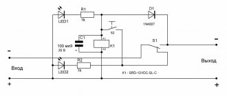
Let's understand the circuit of a simple photo relay with our own hands
The simplest photo relay circuit consists of two transistors, a photoresistor, a relay, a diode and a variable resistor. Devices of the KT315B type are used as transistors, connected according to the circuit of a composite transistor, the load of which is the relay winding. This circuit has a high gain and high input resistance, which allows it to include a photoresistor with high resistance.
With increasing illumination of the photoresistor connected between the collector and the base of the first transistor, this transistor and transistor No. 2 open. As a result of the appearance of current in the collector circuit of the second transistor, the relay will operate, which, with its contacts, depending on its settings, will turn on or off the load.
To protect the circuit from the effects of self-induction EMF when the relay is turned off, a protective diode of type KD522 is included. To adjust the sensitivity of the circuit, a variable transistor with a nominal value of 10 kOhm is connected between the base and emitter of the first transistor.
Such a photo relay can be powered from a DC voltage source of 5 - 15 V. In this case, with a source voltage of 6 volts, relays of the RES 9 or RES 47 type are used, and with a supply voltage of 12 V, relays RES 15 or RES 49 are used.
To mount the circuit, you can create a special board, if possible a printed circuit board. Then attach relays, transistors, a variable resistor to the board, make holes for the terminals of the circuit elements and make the appropriate connections using mounting wires and a soldering iron.
At the required illumination, the circuit's response threshold is selected using a variable resistor. If in the future it is not planned to adjust the response threshold, then instead of a variable one, a constant resistor is installed, the resistance of which corresponds to the value obtained during adjustment.
DIY outdoor LED floodlight installation
LED floodlights for illuminating suburban areas have become very popular today. They are economical, provide a powerful, bright beam of light, and perfectly illuminate a certain area. For more efficient use, motion or light level sensors are additionally installed, which automatically turn on the lamps when moving or when it gets dark. You can choose and purchase high-quality and inexpensive LED spotlights here.
One of the advantages of LED street lights is the simplest installation, which you can do yourself
Site selection When planning installation, careful attention should be paid to site selection. According to accepted safety standards, street floodlights can be mounted at some distance from flammable materials and surfaces
High-power lamps must be installed so that there is an air gap between the housing and the wall. Additionally, you can protect the surface (especially wood) with a sheet of tin. When using light and motion sensors, care should be taken that they are not obscured, otherwise they simply will not work. The position of the future spotlight depends on the requirements for illumination and the direction of the light beam: • car parks and areas in front of the house are illuminated by lamps, the light from which is directed vertically downwards; • gates near the garage or fence are illuminated by spotlights, the beam of light of which is directed horizontally; • for paths, lawns, and facade walls, you can use lamps whose luminous flux is directed strictly upward.
The procedure for installing an LED spotlight The procedure for installing an LED spotlight on the street with your own hands includes the following steps: • a cable is pulled to the installation site, observing all safety standards and regulations (it is best to use a multi-core copper cable); • the lamp is applied to the selected place, with a simple pencil you should carefully mark the fastening points on the surface, check their horizontalness with a building level; • the spotlight is screwed on with self-tapping screws, the type of which depends on the surface material (wood or metal); • when fastening to a concrete wall, you must first drill holes for dowels or metal anchors with a hammer drill; • the spotlight is firmly mounted on the wall; it should not move or wobble easily.
The next step is to connect the lamp to the electrical network: • the line is de-energized; using an indicator screwdriver, you should additionally check that there is no phase on the cable (all measures should be taken to ensure that it does not appear accidentally); • the lamp contact box opens (it is located outside or inside the spotlight body, which depends on its model); • the power cable is inserted through a small hole (it has a special seal that protects the box from moisture); • power wires are connected to the terminal block (black or blue wire goes to zero, yellow or green goes to ground, brown or red goes to phase); • the box cover is put in place, all screws are tightened, after which it is necessary to check the installation of all seals; • the lamp is put in place, electricity is connected; • The spotlight can be turned on to check that the work has been done correctly.
Attention: When checking the performance of the spotlight, you should remember that it does not cool down immediately after turning off, remaining very hot for some time! If you purchased a 12 V spotlight, a mandatory connection element is a separate power supply or transformer, which is not required if you use conventional energy-saving lamps. A large selection of which is here https://salonlustr.com.ua/c9_14-Lampi_energosberegayushchie
Outdoor LED floodlights can be mounted in any convenient place. To save energy, it is best to immediately provide a special motion sensor that turns on the lamp if any moving person or object enters its field of view. Such sensors can be equipped with light indicators that turn off lamps during daylight hours.
WE RECOMMEND READING
- 08/04/2016Which lighting to choose for a nursery
- 09.29.2014Installation of electrical wiring in a wooden house
- 11/24/2014 Faceted metal support for lighting
- 11/24/2014 We understand electric household boilers
Electronics for everyone
Surely many people will want to attach a photodetector to the AVR in order to at least monitor the presence or absence of light. This is useful both for robot builders and for those who make all kinds of automation. So, I will briefly describe what types of photodetectors there are.
Photoresistor
IMHO an endangered species. The last time I saw him was when I was a child. Usually it is a round piece of metal with a glass window in which you can see something like this. When illuminated, its resistance drops, albeit slightly, by a factor of three to four.
Phototransistor
Lately I keep coming across them; an inexhaustible source of phototransistors is five-inch disk drives. The last time, for the price of dirt, I got 5 pieces of disk converter scarves at a radio flea market, where the light transistors are located opposite the holes for controlling the recording and rotation of the floppy disk. There is also a dual phototransistor (and maybe a photodiode, depending on your luck) in an ordinary ball mouse. It looks like a regular LED, only the body is transparent. However, LEDs are also the same, so it’s hard to confuse which one is which. But it doesn’t matter, the partisan can be easily calculated with a regular multimeter. It is enough to turn on the ohmmeter between its emitter and collector (it does not have a base) and shine a light on it, and its resistance will collapse simply catastrophically - from tens of kilo-ohms to just a few ohms. The one that I have in the gear rotation detector in the robot changes its resistance from 100 kOhm to 30 Ohm. A phototransistor works like a regular one - it holds current, but the control action here is not the base current, but the luminous flux.
Photodiode
Externally, it is no different from a phototransistor or a regular LED in a transparent housing. Also sometimes there are ancient photodiodes in metal cases. Usually these are Soviet devices, FD-cheto brands there. It's a metal cylinder with a window at the end and wires sticking out of the back.
Unlike a phototransistor, it can operate in two different modes. In photovoltaic and photodiode. In the first, photovoltaic, version, the photodiode behaves like a solar battery, that is, if you shine light on it, a weak voltage appears at the terminals. It can be strengthened and applied =). But it is much easier to work in photodiode mode. Here we apply reverse voltage to the photodiode. Since, although it is a photo, it is a diode, the voltage will not go in the opposite direction, which means its resistance will be close to a break, but if it is illuminated, the diode will begin to be very strongly undermined and its resistance will drop sharply. And sharply, by a couple of orders of magnitude, like a phototransistor. Range
In addition to the type of device, it also has a working spectrum. For example, a photodetector focused on the infrared spectrum (and most of them are) practically does not react to the light of a green or blue LED. It reacts poorly to a fluorescent lamp, but responds well to an incandescent lamp and a red LED, and there’s nothing to say about infrared. So don’t be surprised if your photo sensor doesn’t react well to light, maybe you made a mistake with the spectrum.
Connection
Now it's time to show how to connect it to the microcontroller. With a photoresistor everything is clear, there are no problems here - you take it and hook it up as per the diagram. It’s more complicated with a photodiode and phototransistor. It is necessary to determine where its anode/cathode or emitter/collector is. This is done simply. You take a multimeter, put it in diode testing mode and hook it to your sensor. The multimeter in this mode shows the voltage drop across the diode/transistor, and the voltage drop here mainly depends on its resistance U=I*R. You take it and illuminate the sensor, monitoring the readings. If the number decreases sharply, then you guessed right and the red wire is on the cathode/collector, and the black wire is on the anode/emitter. If it doesn't change, swap the pins. If it doesn’t help, then either the detector is dead, or you are trying to get a reaction from the LED (by the way, LEDs can also serve as light detectors, but not everything is so simple. However, when I have time, I will show you this technological perversion).
Now about the operation of the circuit, everything is elementary here. In the darkened state, the photodiode does not pass current in the opposite direction, the phototransistor is also closed, and the photoresistor has a very high resistance. The input resistance is close to infinity, which means the input will have full supply voltage aka logical unit. As soon as you now illuminate the diode/transistor/resistor, the resistance drops sharply, and the terminal turns out to be firmly planted on the ground, or very close to the ground. In any case, the resistance will be much lower than the 10 kOhm resistor, which means the voltage will drop sharply and will be somewhere at the level of logical zero. In AVR and PIC you don’t even need to install a resistor; an internal pull-up will be enough. So DDRx=0 PORTx=1 and you will be happy. Well, turn it around like a regular button. The only difficulty that may arise with a photoresistor is that its resistance does not drop so sharply, so it may not reach zero. But here you can play with the size of the pull-up resistor and make sure that the change in resistance is enough to transition through the logic level.
If you just need to measure illumination, and not stupidly catch light/dark, then you will need to hook everything up to the ADC and make the pull-up resistor variable to adjust the parameters.
There is also an advanced type of photo sensors - TSOP
there is a built-in frequency detector and amplifier, but I will write about it a little later.
Photosensor. Part 2. Modulation
Z.Y.
I have some problems here, so the site will be very slow with the update, I think it will be until the end of the month. Then I hope to return to the previous rhythm.
Specifications
Supply voltage. Almost all light relays are designed for a supply voltage of 220 V. Sometimes models are sold with power from 12 or 24 V DC or 110 V AC, in which case they must be connected through a step-down transformer.
Load level. This parameter is given for active loads in the form of conventional incandescent lamps; when using fluorescent lighting devices, this parameter is lower. Less commonly, in imported models, instead of load power, the maximum current is indicated.
Operation threshold. It is usually adjustable in a wide range of 2-300 Lux. To save energy, the lowest response threshold is set - 2 Lux, corresponding to the illumination of deep twilight. Cheap photo relays (usually from a Chinese manufacturer) do not have an adjustment of the response threshold; their preset response value is 5-15 Lux.
Delay time. There are situations when a short-term light flux hits the photocell (headlights, lighter, flashlight). To avoid turning on the lights on the entire street, there is a delay in the response time when turning on and off. This value varies between 15-60 seconds; some imported models have a response threshold of 100 seconds.
Power consumption at rest. For standby mode, this value is small and ranges from 0.1-0.5 W.
Degree of protection from moisture and dust. Depends on the modification of the relay; outdoor models that meet international standards must have a protection class of IP44. For modifications with an external photodetector, these parameters are set individually for each part of the device. For a remote sensor, the optimal value of the protection parameter is IP45 or IP44; the electronic unit built into the electrical panel can have a degree of protection IP20.
Temperature Range. Photosensors or external external elements must operate correctly in a temperature range of -20 C - + 50 C; some models from foreign manufacturers produce devices with a wider temperature range of -40 C - +70 C.
Connection diagram
You need to connect phase and zero to the input of the light sensor. From the point of exit, the phase goes to the load. This refers to a lantern that should turn on when night falls. The zero for the load should come from the machine or from the zero bus of the electrical panel.
In accordance with the installation rules, it is appropriate to make the connection in the junction box. It must have adequate tightness. This is due to the fact that in most cases the box is placed on the street near the spotlight. The most commonly used connection diagram is shown below:
Additionally, a starter may be needed. It is added to the circuit in cases where you need to turn on a fairly powerful street spotlight located on a pole. A device such as a magnetic starter tolerates inrush currents well, being designed for constant operation of the spotlight.
From this article you could learn how to properly connect a photo relay with your own hands. As you can see, all this work can be done independently without the relevant experience or skills, you just need to follow the diagrams!
Connection diagram of classic photo relays to the consumption line
All types of commercially produced or self-made relays require separate power. Accordingly, two contacts of the device will be intended for the named purposes. Moreover, there are photo relay models without a built-in voltage converter, which means that power is supplied to them not from a 220 V network, but through a separate step-down unit. There may be several lines going to consumers, depending on the number of internal electromagnetic switches. Moreover, the input can be separate for each contact, combined among others, or even integrated with the power supply of the photo relay itself.
The light sensor in most models is built into the body of the device itself, but there are also separate options that allow you to move it away from the device itself. The latter is necessary in cases where the photodetector is not illuminated by controlled lamps, so that the system does not turn into a strobe. That is, when it is dark, the device turns on the lamps. It becomes light - he turns them off. Again it triggers darkness. And so on in a circle.
Single
The previously described model FR-602 and similar ones are connected to the line as follows:
For a large number of energy consumers
To control a powerful load, for example, when connecting a spotlight or numerous lamps, it is better to use intermediate relays. In the role of the latter, appropriate devices are selected that can withstand the passage of a large current sufficient for power supply. An example would be RK-1p/2p (Un), MRP-2, IEK ORM-41F-1, DEKraft PR-102 and the like. Please note that some of the relays of a similar design are designed to control alternating current (AC), while others are designed to control direct current (DC). In addition, the switching voltage may differ to the lower side from the socket rating. The last two factors are important to consider when designing a wiring diagram. If the intermediary relay is powered by direct current, then the photo relay must control the supply of electricity to the conversion unit. Which, once turned on, will activate the electromagnetic contactor, activating the main power line of client devices.
Using other photo relay models
Here is a diagram for connecting a photo relay for another version of the finite state machine - with an external light sensitivity sensor and separate contact lines. Initially it was prepared for FR-7E, but is also suitable for similar models from other manufacturers.
Photo of FR-07E:
Please note that the presented photo relay and the one mentioned earlier differ in the housing, and in particular in the protection of the device from external factors. The FR-601/602 can be safely placed outdoors on the street, while the FR-7E requires the installation of an additional casing for a similar effect. But devices of a similar installation plan are produced with all the necessary fastenings in a standard electrical panel, including prepared mounting locations for the DIN rail.