Relay protection circuit
Now let's move on to designs in which an electromagnetic relay is used as a control element. On the one hand, this somewhat reduces reliability - relay contacts can burn out at high currents. But on the other hand, such circuits are quite simple and can be used with power supplies designed for different output voltages - just select the right type of relay.
On one relay
The design is extremely simple, contains a minimum of parts and does not require adjustment. The only thing, as noted above, is to select the relay based on the operating voltage and the corresponding power.
The device works as follows. In the initial position, LED2 is lit, the load is de-energized. When you press button S2, power is supplied to the coil of relay K1 and it is activated, connecting the load to the power source and simultaneously turning off the button and LED2. In this case, capacitor C1 serves to delay the switching off of the relay while its contacts are switched. Together with the load, power through diode D1 is supplied to winding K1 and it becomes self-blocking. The button can be released. LED1 will light up, indicating that the load is powered.
When there is a short circuit, the voltage in the power circuit of the relay drops and it is released, disconnecting the load and reconnecting the button. LED1 goes out, LED2 lights up. In order to restart the node, you must remove the overload and press the S1 button again.
Important! With the relay indicated on the diagram, the device can be used with a 12-volt power supply or charger. If the source voltage is different, it is necessary to select a relay that is triggered by this voltage.
On a relay and a unijunction transistor
This circuit is somewhat more complicated than the previous one, but it allows you to adjust the protection operation current.
As long as the current through the load does not exceed a certain value, the composite transistor T1, T2 is closed. As the current increases, the voltage drop across the current-measuring resistor R1 causes T1 and T2 to open, and after them, relay K1 to operate. The relay disconnects the load and connects resistor R4 to the positive bus, which prevents the relay from turning off.
To return the structure to its original state, just press button S2. The relay will turn off and the load will receive power again. If the cause of the short circuit is not eliminated, then after releasing the button the protection will work again. The magnitude of the operating current can be adjusted using variable resistor P1.
Important! It is not recommended to hold the S2 button for a long time. If the cause of the short circuit is not eliminated, the power supply will be overloaded and burn out, since the protection unit will be forcibly turned off.
In the block you can use KT805 transistors with any letter, 2SC2562, 2N3054 (T2) and any low-power silicon transistors of the pnp structure. The relay response voltage should be slightly lower than the power source voltage. LED1 “Overload” – any indicator.
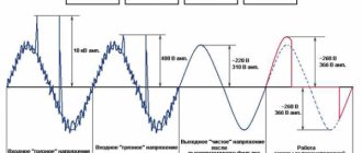
Power Good
Due to the specific design of the device, when turned on, the output voltage does not reach the required value instantly, but after 0.02 seconds.
In order to prevent the supply of low voltage to energy consumers, which can negatively affect their operation, and to provide the necessary ratings of 3.3, 5 and 12 Volts, ATX units have a special line that signals the normal operation of the power supply.
This cable is marked gray and, like the others, is connected to the motherboard. If there is no signal on the line, the computer simply will not turn on.
Power supply overload protection
In most simple units, the power supply is protected from overload only when the maximum load current is exceeded. Such electronic protection is primarily intended for the power supply itself, and not for the load connected to it.
For reliable operation of both the power supply and the electronic device connected to it, it is desirable to be able to change the current protection threshold within wide limits, and when the protection is triggered, the connected load must be de-energized.
The circuit presented in this article is another version of a laboratory power supply, which allows for smooth adjustment of all the parameters listed above.
e-Fuse electronic fuses
Active or, as they are also called, electronic fuses of the eFuse series manufactured by Texas Instruments are completely free from the disadvantages inherent in passive protection circuits. Essentially, an electronic fuse is a low-resistance field switch circuit with integrated control circuitry and circuits for monitoring current flow and input voltage levels. The block diagram of the eFuse electronic fuse is shown in Figure 3.
Rice. 3. Structure of eFuse electronic fuse
The circuit is connected to the power supply circuit and provides protection of the load circuits from increased inrush current, short circuit current, input voltage surges, low voltage, as well as from erroneous reversal of input voltage polarity.
Thresholds can be set by external circuits (resistors or a resistive voltage divider) or, for example, from the output port of a microcontroller that monitors the state of the power supply circuits of a device or system. The electronic fuse is triggered automatically when one of the specified alarm events is detected: exceeding a specified current level, reducing the input voltage level below the norm, exceeding the voltage level above the norm, or incorrect polarity of the input voltage.
Electronic fuses are available both with a built-in switch, ensuring operation in circuits with currents up to 12 A, and for use with an external power transistor. The eFuse external key fuse provides higher switching current levels. In addition, depending on the specified type of protection in the fuses, one of the protection scenarios can be used: automatic restoration of switching after the disappearance of an emergency situation or latch of an emergency event. In the second case, to return to normal operation, the power source must be restarted with the participation of the operator or under the control of a microcontroller that monitors the power circuits.
Power supply parts
Transistor VT2 can be changed to KT315B - KT315E. Transistor VT1 can be replaced with any one from the KT827, KT829 series. Diodes VD2 - VD4 can be used KD522B. Resistance R13 can be assembled from three parallel-connected MLT-1 resistors with a resistance of 1 Ohm each. Zener diode VD1 is any with a stabilization voltage of 7...8 volts and a current of 3 to 8 mA. Containers SZ, C4 are arbitrary film or ceramic. Electrolytic capacitors: C1 - K50-18 or similar foreign, others - grade K50-35. Button SA1 without fixation.
Source: Radio, 9/2006
Option 1
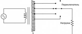
This protection is the simplest and differs from similar ones in that it does not use any transistors or microcircuits. Relays, diode isolation - that’s all its components.
The scheme works as follows. The minus in the circuit is common, so the positive circuit will be considered.
If there is no battery connected to the input, the relay is in the open state. When the battery is connected, the plus is supplied through the diode VD2 to the relay winding, as a result of which the relay contact closes and the main charging current flows to the battery.
At the same time, the green LED indicator lights up, indicating that the connection is correct.
And if you now remove the battery, then there will be voltage at the output of the circuit, since the current from the charger will continue to flow through the VD2 diode to the relay winding.
If the connection polarity is reversed, the VD2 diode will be locked and no power will be supplied to the relay winding. The relay will not work.
In this case, the red LED will light up, which is intentionally connected incorrectly. It will indicate that the polarity of the battery connection is incorrect.
Diode VD1 protects the circuit from self-induction that occurs when the relay is turned off.
If such protection is implemented in a car battery charger , it is worth taking a 12 V relay. The permissible relay current depends only on the power of the charger . On average, it is worth using a 15-20 A relay.
Reverse polarity protection device for charger. | Master Vintik. Everything with your own hands!
A simple circuit for protecting the battery and charger from polarity reversal
But when searching the Internet for the required scheme, I did not find anything similar. And before that I saw it a year ago. I drew a diagram from memory and am ready to share it with you.
This device is needed to protect your battery and charging from damage, preventing you from mixing up the terminals and will save you from many problems.
Here is a diagram of a polarity reversal device for relay chargers.
- Elements:
- R1 = 510 Rel2 = 12V (Any 12V 10-15A, removed from a former UPS for a computer, can be used with a car)
- VD1-3= 1N4007 (or similar).
Although VD3 is not required, you can use a jumper instead. VD1 from the self-induction of the relay coil.
This is how the device works. When you connect a battery, the remaining charge in it passes through the relay and closes the contacts, thereby supplying current from the charger to the battery.
If you connect the wires to the battery incorrectly, then VD2 will not allow electricity to pass through the relay and charging will not start. And instead of charging, the LED will light up, indicating that the charging is not connected correctly.
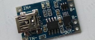
Here is a reverse polarity protection device for a PCB charger.
Reverse polarity protection device seal for the charger.
- You can use this link to download the Sprint-Layout 5.0 reverse polarity protection device seal for the charger
- Source: malmon.ru
- Charger diagram for IPod, IPhone
- Homemade automatic battery charger
- More information about charging and discharging a car battery
The circuit proposed below on the MC34063A allows you to charge your iPod without connecting it to a computer. Using a computer's USB port to charge the battery is not always practical. For example, there is no computer at hand or there is no need to turn it on because it is charging. Cell phone chargers for iPods and MP3 players are available, but they are expensive and you need to have separate charging options at home and in the car. Read more…
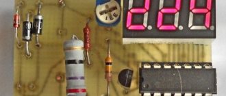
A simple charger with current regulation and charge control for a car battery
The battery is one of the important elements in a car. It needs to be monitored and charged on time, especially in winter, and also when the car has not been used for a long time. For this you need a charger. You can buy it, or you can assemble it from inexpensive parts, which will cost much less than a store-bought one, but in terms of characteristics and reliability it is superior to some copies currently sold. After remaking a whole bunch of chargers, I finally assembled a fairly simple charger with current regulation and automatic charge control. Read more…
A car battery ( AK battery ) is one of the most important parts of a car . The battery provides electricity to: electric lamps in the headlights, instrument panel and interior lighting, the vehicle's electronic ignition system, fuel pump, car radio and other vehicle components, as well as the most consumed load source - the starter when starting the engine. Normal operation of all vehicle components is possible only with a properly used battery. It must be serviced and charged on time. Read more…
Popularity: 17,828 views.
Source: https://www.MasterVintik.ru/ustrojstvo-zashhity-ot-perepolyusovki-dlya-zaryadnogo-ustrojstva/