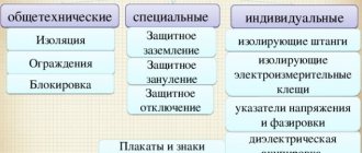
Testing metal connections will protect people and save energy
If you ignore regular checks, the contacts of the grounding network (with the exception of sealed connections) will oxidize and collapse under the influence of environmental factors. This leaves two disconnected circuit links with different electrical potentials. If a person touches them, he will act as a conductor, passing current through his body from one part to another, which will cause injury or lead to death.
Voltage of any magnitude is dangerous for humans. For the heart muscle, current is dangerous starting from 30 mA, and when exposed to a current of 90-100 mA, breathing may stop within a few seconds. High current instantly increases body temperature, burning out the body's cells, while low current causes cardiac arrest or disruption of brain activity.
Contact connections between parts exhibit increased resistance when compared to a solid conductive surface. When the metal connection is broken, the transition resistance increases, which is determined when current passes from one structural element to the next part of the circuit.
What is “metal bonding”?
This term is usually understood as a connection (electrical circuit) formed by an electrical installation and a ground electrode. The main requirement for metal communications is the continuity of the grounding circuit. Violation of this condition threatens the formation of a high potential difference in the circuits of the electrical installation, which poses a threat to life and may lead to equipment failure.
Reliable contact of the grounding conductor and the grounding object ensures a low value of transition resistance
Over time, there may be an increase in transient resistance in the grounding circuit, which leads to the formation of metal bond defects; let's look at the nature of this phenomenon.
Contact the specialists
Regular checks of the integrity of grounding loops by certified specialists are a guarantee of the safety of enterprise employees, lower operating costs by reducing “waste” energy consumption and reducing the risk of fire.
Employees will conduct an examination of the electrical circuit elements to which access has been granted. Using precision instruments, the transition resistance will be measured, the readings will be recorded in a protocol and transferred to the Customer.
During testing, equipment is not excluded from the work process, so testing metal communications does not affect the productivity of the enterprise. The work is carried out in a short time and at an affordable cost.
Step-by-step measurement of metal connections
The audit includes a number of analytical techniques, which together provide a comprehensive analysis of the current situation and indicate the presence of problems. The research is divided into the following stages:
- Visual inspection;
- Mechanical load testing (welded joints by lightly tapping with a hammer);
- Checking contacts, connections and fasteners;
- Checking the cross-section of grounding conductors for compliance with the PUE;
At the first stage, a laboratory employee examines the parts of the grounding conductors that are included in the metal connection. Visually determines the absence of defects and damage. Inspects the integrity of the insulating coating, the absence of traces of oxidation and corrosive destruction. The specialist taps the welding joints with a hammer to make sure that the seams and contacts are intact.
After this, current-conducting elements, bolted and contact connections are checked, which may be weakened during operation of the electrical installation.
Why measure?
Grounding is the basis for safety in electrical installations and outlets. All electrical devices and apparatus must be grounded. This is necessary in order to avoid electric shock in an emergency. Checking the metal connection is necessary in order to make sure that all ground lines are in good contact.
The results of the test are recorded in the metal bond measurement protocol. You can see a sample of how to fill it out in the photo below. After that, conclusions are drawn about the general condition of the grounding contacts and, if necessary, problems are eliminated.
Maintaining normal metal communication allows you to:
- Avoid electric shock to both electrical workers and others.
- Eliminate hot contacts, reduce the risk of fire.
- Reduce energy leakage (heating of contacts).
We have looked at why this procedure is needed, let’s find out how it is carried out.
How to check circuit integrity
Before testing the electrical installation for the continuity of protective conductors, it is de-energized. The employees of our mobile electrical laboratory (ETL) take measures to ensure the safety of work in accordance with safety standards.
Monitoring helps to establish the degree of reliability of metal communications:
- for the continuity of highways and wiring;
- the condition of connecting nodes made by welding or bolting;
- behind the transition resistances of the circuits connecting the grounding conductors and the grounded parts of the power plant.
The quality of connecting nodes, continuity of lines and connections is initially determined by visual inspection
Attention is paid to their integrity and the presence of corrosion defects. Welding joints are tapped with a hammer
Diagnostic measures for checking the circuit between grounded installations require, like other work in the power plant, strict adherence to labor protection instructions. Therefore, conducting them in the rain or at high air humidity is prohibited!
There are no strict standards for transition resistances. Nevertheless, the electrical resistance of the entire metal communication circuit, taking into account the contacts, must have an actual value of no more than 1.2 times higher than the calculated one or not exceed 0.05 Ohm (PTEEP, Appendix 3, Section 28.5).
If the specified parameters are not met, then the contacts are subject to a more thorough check
Particular attention is paid to the connections of grounding wires with the housings of the power plant, as well as with the main grounding clamp. It may be necessary to disassemble and clean their bolted connections.
After the contacts are restored, the electrical test of the circuit between the grounding conductors and the grounded elements is performed again.
In installations with a solidly grounded neutral with an operating voltage of up to 1000 V, the operation of the protective automatics must be monitored.
How to check metal connections in electrical installations
The technique for checking metal connections consists of measuring the transition resistance in different sections of the neutral protective conductor. Its normal value is ≤ 0.05 Ohm. A higher value of contact resistance indicates problems with contact connections: weak welded joint, oxidation, etc. The maximum permissible discrepancy in the measured and calculated resistance of the conductor circuit is 20% up and down.
- visual inspection of protective conductors;
- mechanical inspection of welded joints;
- checking metal connections on all grounded elements of the electrical installation;
- determination of voltage on the body of grounded electrical equipment.
In the electrical laboratory of IC "OLIMP", metal connections are checked by professional and experienced certified specialists. To order a service, contact us in a convenient way.
Upon completion of the installation of electrical equipment, as well as during its operation, it is necessary to carry out a set of electrical measuring measures, among which there is also such a type of test as checking metal connections. What is metal bonding and what is the purpose of measurement, we will analyze further.
Servicing electrical installations is permitted only to personnel who have undergone special training and knowledge testing. The qualifications of specialists are confirmed by certificates of the appropriate type.
There are also separate requirements for the equipment itself - climatic design, installation method, safe operating conditions and other aspects that require strict compliance.
These include the presence of protective grounding on metal cases.
The definition of “metal bond” among electricians characterizes the presence and quality of protective grounding. Checking metal connections means determining the transient ohmic resistance between the ground loop and the grounded electrical equipment.
For this purpose, the third core in the wiring of private houses (apartments) and the fifth core in the electrical networks of industrial enterprises are specially included in power supply projects to organize the TN-CS system - the most common grounding system in electrical installations up to 1000V today.
The purpose of checking metal connections is to determine the parameters of grounding circuits that characterize the electrical safety of the installation.
Based on the fact that in the event of an emergency mode (breakdown of the insulation of current-carrying parts), the current will follow the path of least electrical resistance, the Electrical Installation Rules (PUE) establish strict standards for the cross-section of grounding conductors and the value of transition resistance. The resistance of one connection (contact) should be equal to no more than 0.01 Ohm with an error of up to 20%, however, for grounding, at least two connections (welded or bolted) along with the conductor are required, therefore employees of the electrical engineering laboratory (ETL) when making measurements are based on the value of the total transition resistance is 0.05 Ohm.
Metal bond measurements are carried out immediately after installation of the electrical installation, right before start-up and commissioning. In addition to the metal bond test report, a ground loop resistance measurement protocol may be required.
After the start of operation of electrical equipment, engineering and technical workers responsible for electrical facilities, in accordance with the requirements of PTEEP (Rules for the Technical Operation of Consumer Electrical Installations), carry out repeated measurements of metal connections at least once every 3 years (clause 2.
12.17). This is due to the fact that over time, the appearance of oxides, dust, weakening of contacts and a number of other factors leads to a gradual increase in ohmic resistance, and it is very important to control that this process does not exceed the established regulatory framework.
To carry out measurements, employees of an electrical measuring laboratory accredited by Rostechnadzor are involved. The methodology and general procedure for checking metal connections in electrical installations can be divided into several stages:
- External visual inspection. Involves a visual inspection of the ground loop for integrity and the presence of defects, which can be caused by both natural aging (corrosion) and mechanical damage during service life. Particular attention must be paid to contact connections. Grounding systems use welded, bolted, soldered and crimped connections. Welds are tapped with a hammer to determine mechanical strength and weld quality. Bolted connections are usually simply pulled through to improve contact.
- Measurement of contact resistance. This is done as follows: one probe of the test device is installed on the grounding strip, the other probe is installed on the grounded electrical installation. This may require partial stripping of the surface from the protective coating (varnish or paint). The data is written and moves on to the next element. If the result is unsatisfactory, the connections are checked again, cleaned and pulled or crimped, after which measurements are taken again.
- Recording the results. At the end of the tests, the data obtained during measurements are entered into a document of the established form - a test report. In addition, the protocol contains information about the customer for whom the measurements were made, the name and registration number of the ETL that carried out the electrical measuring work, data on test equipment with a verification period, the name and geophysical parameters of the device or installation being tested, the number of tested elements of the grounding system and conclusions about suitability for operation. After filling out all the columns, the signatures of the employee who carried out the measurements and the head of the ETL are affixed. The reliability of the protocol is confirmed by the blue seal of the electrical laboratory.
Metal communication test protocol
Instruments for testing metal bonds must be specialized.
On the modern market there is a huge range of devices, both domestic and foreign.
Their feature is a wide range and high accuracy of measuring ohmic resistance (from 1 to 100,000 μOhm with an error of ±0.2%).
Among the Russian instruments, one can highlight the IKS-5 and MIKO-1 microohmmeters, and among the foreign ones, the MIC-3 ohmmeter and the Fluke multimeter. The main criteria by which a device is selected are as follows:
- silicone measuring leads that do not harden in subzero temperatures;
- the presence of a built-in power source (rechargeable battery), allowing work to be carried out in the field without the presence of external sources;
- high degree of protection against moisture and dust.
READ MORE: Review of methods for measuring ground resistance
Conclusion
An important point in carrying out acceptance and preventive inspections of electrical equipment is the correct choice of electrical measuring laboratory.
Only an organization that has the appropriate accreditation from Rostechnadzor indicating the permitted types of measurements has the right to conduct electrical tests.
Personnel whose responsibilities include direct testing and measurement must also undergo appropriate training. While performing their official duties, specialists must carry a qualification certificate with them.
accepts orders for measurements of metal communications in the territory of Moscow and the Moscow region. Our specialists will complete the work in the shortest possible time, drawing up the necessary protocols and technical reports.
You can ask questions or get more detailed information by contacting us at the numbers listed in the “Contacts” section.
Metal communications and impact on fire protection
Fire protection in electrical installations is a systematic check of all connections for strength. When high resistance occurs, the contact terminals begin to heat up, the insulation and other fusible materials heat up, and with a prolonged increase in the heating of the contacts, a fire occurs.
To timely identify unreliable connections, regular checking of the value of metal bonds using a thermal imager is used, since using this device you can much more easily and quickly identify even slight heating of connections and promptly eliminate the causes (loose bolted connections, accumulation of dust, dirt, corrosion).
Causes of the phenomenon
Total resistance
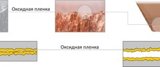
A contact connection connects sections of an electrical circuit with each other. Where the connection occurs, a conductive mutual contact is obtained, through which the current passes from one section of the circuit to another. Conventional overlaying of surfaces does not produce a quality connection. This is due to the fact that real surfaces are irregularities with protrusions and depressions. With sufficient image magnification, this can be observed even on polished planes.
Contact patch under a microscope
Attention! In practice, it turns out that the area of actual contact is much smaller than the entire contact area. Another reason for the occurrence of such resistance is the metal oxidation films present on the surfaces
They impede the movement of electricity and draw current lines to the points of contact. It is impossible to completely get rid of this resistance. Its value is always greater than the resistivity of the metals from which the conductors are made
Another reason for the occurrence of such resistance is the metal oxidation films present on the surfaces. They impede the movement of electricity and draw current lines to the points of contact. It is impossible to completely get rid of this resistance. Its value is always greater than the resistivity of the metals from which the conductors are made.
Microstructure of electrical contact
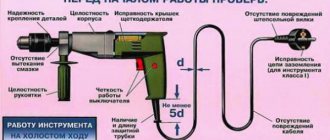
Test method
Contact with the main grounding bus can be bolted or welded. Checking metal connections requires an accurate instrument - a milliohmmeter, capable of measuring values of 0.01 Ohm and more accurate, but not vice versa. The measurement is carried out with a multimeter, if the latter meets the accuracy and sensitivity class. Devices must be verified. It will not be possible to check with a regular dial; it will show the presence of a contact, but its quality will remain unknown.
Checking and measuring metal connections begins with an external inspection of the entire installation, focusing on:
- Presence of breaks in grounding buses and wires. They can crack, tear, be destroyed by corrosion, etc.
- Quality of bolted connections. All bolts must be securely tightened, and the bars and cable lugs must not move, i.e. should not move under any force applied.
- Quality of welded joints. They are additionally tapped with good, but not too strong, hammer blows. This is done to detect cracks, the main thing is not to damage serviceable components.
How is the check performed? Each metal element of the structure must be grounded:
- racks and metal frames;
- load-bearing elements;
- marching stairs;
- lifting mechanisms;
- trays in which the wires are located;
- cable galleries;
- electrical panels;
- welding stations;
- panel doors and so on.
In order to measure resistance, the first probe is placed on the main grounding bus, usually it is marked with green paint with short yellow stripes, and the second probe is placed on the metal connection element with which they plan to measure. There must be a minimum number of connections from the final node or mechanism to the main gearbox.
The resistance of one transition contact should be 0.01 Ohm, its permissible excess is 20%. If there are several transition contacts from the element being measured to the main ground bus, then their total resistance should be no more than 0.05 Ohm. If the measurement results differ from the standard values, the contact should be improved.
For bolted ones - either just broaching, or disconnecting, cleaning adjacent planes and broaching, bringing the resistance up to standard, if the previous did not help. If metal elements are connected not by buses, but by a flexible wire, you should also check the wire for a break, because the resulting metal bond resistance in this case increases. Welding connections must be restored. After these procedures, you need to check the resistance again.
The standards for metal bond measurements and their results are discussed in detail:
- PUE-7, section 1.7;
- PTEEE, p.p. 26, 28;
- GOST R 50571.16;
- GOST 12.2.0-75, clause 3.3.7;
How often to measure grounding PS
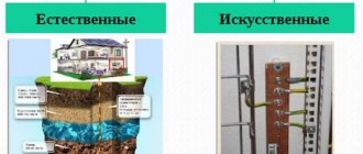
Grounding is a special connection of equipment to a grounding device (GD).
The memory is a device consisting of the following elements:
- grounding conductor (grounding circuit);
- grounding buses;
- grounding conductors.
A full inspection, including opening the soil and inspecting the condition of the grounding conductors and the conductors connecting them, is carried out once every 12 years. Unscheduled inspections are carried out after major repairs related to grounding elements. The period for checking and measuring the PS memory is assigned based on the recommendations of the organization that performed the previous check.
The value of Rп, which lies within the regulated standards, ensures stable operation of switching devices. This, in turn, contributes to the uninterrupted and safe operation of the equipment.
Professional equipment is the key to inspection accuracy
After a visual inspection, meters are used to show the transition resistance of the contacts and connecting elements of the ground loop. During the test, all available elements are analyzed using instruments of increased sensitivity. In accordance with current regulations, metal structures (casing, doors, shelves, ventilation ducts, fastening elements, metal cable duct) that come into contact with electrical equipment must be combined into serial electrical circuits, each of which must be grounded.
When checking a section of an electrical circuit, the control probes of the analyzing device are installed on both sides of the section being tested. A branch is formed through which a current flows corresponding to the resistance of the contact part. If several parts of the same circuit are tested, the terminals are installed at the extreme points of the circuit. The measurement of metal bond resistance is carried out between the main grounding bus and each part that is connected to it into a single structure.
The standards prescribed in the electrical installation rules (PUE) limit the device readings to 0.01 Ohm. The discrepancy with the reference value should not exceed 20%. If there are several transitions between the element under study and the grounding bus, the resistance can be increased to 0.05 Ohm. If the meter data falls outside the specified limits, the engineer checks for oxidation, signs of corrosion and the integrity of the contacts, cleans them and re-analyzes them. If the equipment data does not change, then the grounding elements will need to be replaced.
Measuring instruments
Instruments for testing metal bonds must be specialized. On the modern market there is a huge range of devices, both domestic and foreign. Their feature is a wide range and high accuracy of measuring ohmic resistance (from 1 to 100,000 μOhm with an error of ±0.2%).
Among the Russian instruments, one can highlight the IKS-5 and MIKO-1 microohmmeters, and among the foreign ones, the MIC-3 ohmmeter and the Fluke multimeter. The main criteria by which a device is selected are as follows:
- silicone measuring leads that do not harden in subzero temperatures;
- the presence of a built-in power source (rechargeable battery), allowing work to be carried out in the field without the presence of external sources;
- high degree of protection against moisture and dust.
Why does the contact resistance increase?
The term “contact connection” refers to two metal elements in contact with each other. Even if you polish them to a mirror shine, you will not be able to get rid of the microscopic tubercles. The contact area of these roughnesses can change under the influence of external reasons: for example, a screw connection has become loose - and the plates have moved away from each other, the temperature has risen, and due to the expansion of the metal, the surfaces are pressed closer to each other...
Metal objects are constantly affected by vibration and temperature changes. Housings and other elements may be subject to accidental mechanical damage. Finally, moisture in the air causes corrosion of the metal, which also negatively affects the quality of the fasteners. All this leads to a decrease in the contact area of metal surfaces, resulting in an increase in resistance.
If such deviations are not noticed in time, numerous emergency situations are possible: from electric shock to a person when touching metal parts to fires or failure of valuable equipment.
The resistance value is also affected by the state of the contacts: as is known, oxygen contained in the air gradually oxidizes metals, and the rate of formation of oxide films depends on the type of metal. Thus, aluminum conductors oxidize faster than copper conductors, which means, other things being equal, the resistance in them will also increase faster.
What is metal bonding and how is it checked?
The use of the term “metal bond” in electrical engineering is associated with the need for a qualitative assessment of the reliability of contact between individual elements forming grounding. A decrease in this indicator (lack of good metal communication), as a rule, is explained by errors made during the installation of the system. Such defects lead to gradual oxidation of the metal in the contact zone and an increase in the contact resistance in this place. As a result of such violations, the system ceases to correspond to its intended purpose (that is, it does not provide protection against electric shock).
Features of metal bond measurement
Experts use the term “metal bond” to refer to the common circuit between grounding and grounded elements. Checking the presence of such a circuit is called checking the metal connection.
The meaning of this activity comes down to measuring the transition resistance in those places where the grounded elements are in contact with the grounding conductors. Using a typical electrical panel as an example, it looks like this:
- Doors, housing, sockets and PE buses are non-current-carrying parts, that is, they should not conduct electricity. To do this, they are grounded.
- When checking metal connections, the resistance value at the contact points is measured and compared with standard values. Ideally, the value should not be higher than 0.05 Ohm.
- The inspector also monitors for breaks in the ground connection - in this case, the resistance will be higher than the maximum permissible value.
The test is carried out using a low resistance meter, which is sensitive enough to detect even such small values.
All results are recorded and entered into the final protocol. For express diagnostics, it is possible to use thermal imagers: they clearly demonstrate heating contacts, thereby signaling the presence of problems in metal communications.
How often to measure grounding PS
Grounding is a special connection of equipment to a grounding device (GD).
The memory is a device consisting of the following elements:
- grounding conductor (grounding circuit);
- grounding buses;
- grounding conductors.
A full inspection, including opening the soil and inspecting the condition of the grounding conductors and the conductors connecting them, is carried out once every 12 years. Unscheduled inspections are carried out after major repairs related to grounding elements. The period for checking and measuring the PS memory is assigned based on the recommendations of the organization that performed the previous check.
The value of Rп, which lies within the regulated standards, ensures stable operation of switching devices. This, in turn, contributes to the uninterrupted and safe operation of the equipment.
Why measure metal bonds?
Over time, the contact resistance at the junction of the elements increases. The reason is a decrease in the adhesion density of the surfaces of two conductors, which is caused by metal oxidation, destruction of fasteners, regular load or an error made at the installation stage.
This impairs the passage of current through the circuit and leads to disruption of the metal bond. As a result, the permissible potential difference between two links of the electrical circuit is exceeded, which creates a threat to human safety (the occurrence of dangerous voltage on the electrical installation body) and increases the likelihood of equipment failure.
Carrying out metal bond measurements will allow you to identify an emerging problem at an early stage and prevent serious consequences. During the research, the specialist will identify possible causes of the malfunction:
- Violation of the integrity of conductive elements and structures;
- Failures in the potential equalization system;
- Destruction of the insulating coating of the wiring;
- The presence of voltage on the body of the electrical installation due to a break in the grounding conductor.
The main purpose of the study is to check the parameters of grounding circuits that can identify current problems or discrepancies with safety standards.
Frequency of checks
The standards prescribed in the rules for the design of electrical installations and the rules for the technical operation of consumer electrical installations (PTEEP) limit the frequency of metal communication measurements in accordance with the object and type of equipment.
Recommended values are defined within the following limits:
- Enterprises and companies working with devices that are on the high-risk list conduct research once a year.
- Objects of low and medium danger levels - at least once every three years.
- Elevators, cranes and lifting equipment are inspected annually.
- Measurements of the resistance of the insulating coating of electrical wiring are carried out once a year.
The inspection schedule is drawn up by the employee responsible for electrical equipment, or approved by the head of the facility on the basis of regulatory and technical documentation.
In addition to standard inspections, metal connections are tested during the installation of new equipment, installation and repair work at the enterprise.
Recording measurement results
Based on the results of the inspection, all obtained values are necessarily recorded in the inspection protocol. The data of the inspected electrical equipment is entered into a special table, the names of the inspected components are indicated, the location of each element is noted, their total number of inspected places is recorded, and the highest values of contact resistance are recorded.
If during the inspection violations are revealed, for example, equipment that is not grounded is found or the maximum permissible resistance values are exceeded, they are also reflected in the protocol and entered into the defect list.
Instead of a conclusion
For non-specialists, it is important to remember that if the neutral conductor and ground are not combined in one wire, then additional grounding is required for all metal elements of the equipment! To prevent emergency situations, all group cable lines (with the exception of light lines) must be equipped with circuit breakers and residual current devices (RCDs). Regular checking of the condition of contact connections of metal elements and grounding conductors is another necessary element of safety guarantee
You should regularly tighten the fastening joints, remove dust, dirt and oxide film from the contact surfaces
Regular checking of the condition of contact connections of metal elements and grounding conductors is another necessary element of guaranteeing safety. You should regularly tighten the fastening joints, remove dust, dirt and oxide film from the contact surfaces.
During electrical measurements, engineers check and record the value of the transition resistance - it cannot exceed 0.1 Ohm. In case of deviation to a large extent, the contact pads should be adjusted (cleaned, tightened bolts and screws) to avoid accidents.
If the check reveals the presence of ungrounded elements, it is necessary to immediately connect to the EPS - potential equalization system. This will help preserve equipment, reduce the risk of fires, and minimize incidents of electrical injuries.
Regular checks for the presence of metal connections and measuring the value of contact resistance will allow you to identify defects before current leakage leads to human, technical or financial losses.
Of course, any electrical equipment has many other components and contact connections, which, if defective, can also lead to casualties, ignition and fire. Therefore, our employees are ready at any time to carry out express diagnostics of the condition of electrical panels in order to detect leaks and overheating contacts. Remember, it is better to nip trouble in the bud than to deal with its consequences in the future.
Using modern equipment, diagnostics are carried out in the shortest possible time and do not in any way affect the work processes within the enterprise. To detect defects, specialists will not need to turn off the power - everything that is needed will be shown by thermal sensors and measuring instruments.
Why should you choose ETL LLC "ENERGO-COMMAND" to check the integrity of grounding circuits?
Electrical equipment, regularly checked by our specialists, works properly at the facilities of many well-known companies in the Moscow region and beyond. TELE 2, ADIDAS, ROY ROBSON, ECO KITCHEN, TELECOM PROJECT cooperate with us (see the full list here). A high level of trust is facilitated by the quality of work we guarantee, achieved thanks to:
- participation in electrical inspections of ENERGO-TEAM personnel with appropriate electrical qualifications. Diagnostics are performed by a team consisting of at least 2 specialists with electrical safety groups of at least 3;
- use of modern certified instruments and devices to measure metal bond resistance. For example, such as the Eurotest multifunctional digital meter and the Meteo-10 electronic humidity tester;
- strict compliance with technical regulations, including taking into account the factors specified therein that distort the result. Thus, all measurements are carried out at air temperatures not lower than 00C and not higher than +400C (the optimal range is +10...+300C) and only during daylight hours. The influence of magnetic fields on the operation of laboratory equipment and the monitored memory devices is also taken into account - the devices either move away from the sources of interference, or these sources are turned off.
In addition, we carry out continuity testing of protective conductors at prices no higher than the market average. However, they can be further reduced through the use of certain discounts or individual agreements with the customer.
Still have questions?
Call us right now at:
+7
or submit a request to our email address:
The ENERGO-TEAM team will find a solution to your problems, which will certainly interest you both in the volume of services provided and in its cost!
Why is metal communication necessary?
The main parameter for the quality of metal bonding is the resistance of the measured area (the maximum permissible value is 0.05 Ohm). The correctness and reliability of electrical connections is checked during a thorough inspection. The strength of welded joints is checked by measuring the chain after several blows with a heavy hammer.
Planned measurements of metal connections are carried out in accordance with the PUE, which also stipulate that conductors (protective and potential equalization systems) are subject to high-quality connection to ensure the integrity and continuity of the electrical circuit.
Metal communication according to the method
The welding method is used to connect steel conductors. The connection points are located in such a way that metal connections can be made and that they can be easily reached during future visual inspections, measurements and tests. The exception here is soldered, welded and pressed joints in heating systems that are located in the ground, ceilings, floors or walls.
In accordance with the approved PUE, the connection of conductive parts and potential equalization conductors and grounding and neutral conductors must also be performed by welding or using bolts. Flexible conductors are used for connections in electrical equipment that are either subject to vibration during operation or are frequently dismantled.
To measure contact resistance, a special method is used. This method consists of connecting the first pole of the measuring device to the ground of the element being tested, and the second pole is connected to a certain reference point. A current source is connected between them.
A test such as metal bond measurement is a responsible and complex undertaking. But the electrical measuring laboratory of our company is not only equipped with modern equipment necessary for carrying out such measurements, but also has a staff of experienced electrical engineers, whose extensive experience guarantees the quality and accuracy of electrical measurements.
Validation Rules
First of all, a visual inspection of the elements of the protective system is performed. At the same time, the functionality of the electrical joints is inspected. At this stage, the welding joints must be tapped with a sledgehammer or other tool. This will make sure of the high (or low) degree of their strength. After this, a visual inspection of the bolted or terminal contacts is carried out. This will make it possible to identify scratches, cracks or chips on them. At the same time, the degree of tightening is checked tactilely (by touch). This is the best way to find out if the connection is broken. Sometimes an increase in temperature in the joint area is felt. This means that the metal connection is weakened here. When the visual inspection of the contacts is completed, the measurement of the contact resistance begins. The following is inspected: - the circuit of existing terminal or bolted joints; - welding area. Finally, the laboratory specialist begins checking the entire installation based on the collected data. His task is to find out how the system complies with the PUE standards. This includes checking the conditions for spreading electricity. To implement this stage, sequential measurements of the contact resistance of all contacts are carried out. The chain must include: - GZSh terminals; - equipment grounding buses; - points of connection to the ground electrode. In order for the metal connection to be of high quality, the contact resistance should not exceed the level specified by the standards. The cross-sectional area of each protective conductor is shown in the table.
NEWS
March 10, 2020
Over 10 years (from 2009 to 2022), the annual technological losses of electricity in the networks of Kurgan... Read more>>
March 10, 2020
2022 marks the 100th anniversary of the GOELRO plan (State Plan for Electrification of Russia), which became the first promising... Read more>>
March 10, 2020
On February 19, the dispatcher of the Kurgan city electrical networks received an alarm call: on a high-voltage support... Read more>>
March 10, 2020
On the eve of the summer season, energy workers remind gardeners and land owners: if there is a passage through the site... Read more>>
Registration of the results of testing circuits between grounding conductors and electrical installations
In the process of testing electrical equipment, its results are recorded in a work (laboratory) journal. The obtained values are compared with calculated or standard data. Based on them, a decision is made on the reliability of the connections and the continuity of the storage lines. It is displayed by our employees in the final report - a protocol for checking the circuit between grounding conductors and grounded objects. The protocol is signed by the engineers who conducted the test and the head of the laboratory.
For the reliability of the results displayed in the report, ENERGO-TEAM specialists are responsible in accordance with the legislation of the Russian Federation and the requirements of the Regulations on Mobile ETL.
Recording the results of metal communication measurements
After carrying out the necessary measurements of the metal connection, the Customer receives a protocol containing the test data and indicators recorded by the engineers. The document includes the following information:
- Marking and designation of electrical equipment that has been checked by a specialist.
- The number and location of the investigated contact elements.
- The result obtained when the device measures a section of a grounded circuit.
If discrepancies are detected with the standard indications of the PUE or a violation of the metal connection of the equipment, an appendix is issued to the main document, which indicates the detected defects.
Metal communications and fire safety: how to protect yourself from fire?
As already mentioned, heat is released in contact connections when electricity leaks. The degree of heating depends on a number of reasons, including: including the features of the metal structure and fastening elements. It should be remembered that the contacts, when heated, provoke a fire in the insulation and nearby parts (for example, plastic).
To avoid an emergency, it is enough to regularly check the presence of metal communications using infrared thermal imagers or pyrometers. They are able to detect deviations at the initial stages and stop possible fires. Just think about it: to avoid a fire, sometimes it is enough to tighten the bolts and screws more tightly, and clean the contacting surfaces of dirt and oxide film. Preventive inspections and measurements are something that really cannot be done without in any organization.