| NAME OF WORKS | UNIT | PRICE |
| Checking the presence of a circuit between grounding conductors and grounded elements (metal connection) | 1 point | 40 rub. |
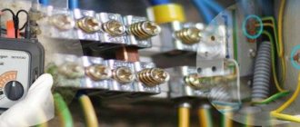
The MOSENERGOTEST electrical laboratory takes measurements of metal connections to eliminate the possibility of defects occurring in the electrical network.
Electrical measurements are carried out by company specialists using high-tech equipment that ensures high accuracy of the results obtained. Metal bonding is an indicator indicating that there is a connection in the circuit between the grounding system and any object, which is used to reduce the risk of fire in electrical installations. Such measurements must be carried out regularly. This procedure makes it possible to find out whether there is any damage in the circuit or whether the operation of electrical equipment has been affected by corrosion. In cases where indicators are not checked regularly, various unpleasant consequences may occur. In addition, electrical equipment that fails as a result of circuit damage can harm the health and life of people. Checking the circuit between grounding conductors and grounded elements must be carried out by professionals with special training and equipment. If you carry out measurements without being technically ready for this, it is not a fact that all test results will be correct, and you will not be injured during the test. Testing metal bond resistance is the job of an electrical laboratory.
What is “metal bonding”?
This term is usually understood as a connection (electrical circuit) formed by an electrical installation and a ground electrode. The main requirement for metal communications is the continuity of the grounding circuit. Violation of this condition threatens the formation of a high potential difference in the circuits of the electrical installation, which poses a threat to life and may lead to equipment failure.
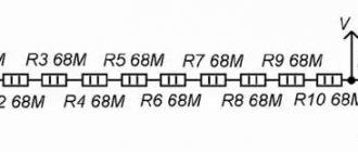
Reliable contact of the grounding conductor and the grounding object ensures a low value of transition resistance
Over time, there may be an increase in transient resistance in the grounding circuit, which leads to the formation of metal bond defects; let's look at the nature of this phenomenon.
Registration of the results of testing circuits between grounding conductors and electrical installations
In the process of testing electrical equipment, its results are recorded in a work (laboratory) journal. The obtained values are compared with calculated or standard data. Based on them, a decision is made on the reliability of the connections and the continuity of the storage lines. It is displayed by our employees in the final report - a protocol for checking the circuit between grounding conductors and grounded objects. The protocol is signed by the engineers who conducted the test and the head of the laboratory.
For the reliability of the results displayed in the report, ENERGO-TEAM specialists are responsible in accordance with the legislation of the Russian Federation and the requirements of the Regulations on Mobile ETL.
What causes the increase in contact resistance?
Transition contacts refer to metal elements in contact. It is impossible to achieve their perfect polishing; all the same, there will be microscopic bumps and dents on the surface. The area of contacting surfaces changes under the influence of various external factors (temperature, pressing force, surface contamination, etc.), which leads to an increase in contact resistance. The electron microscope photographs below of a copper contact show the formation of a copper oxide film on the surface.
Copper contact surface magnified by microscope
Such an oxide film has dielectric properties, although they are not great, but this may be enough to break the metal bond. As a result, the connection will heat up and sooner or later lead to the contact burning out, which will immediately affect the quality of the metal connection. An equally common reason is the human factor, which is why after installation work it is necessary to measure the metal connection.
Testing metal connections will protect people and save energy
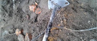
If you ignore regular checks, the contacts of the grounding network (with the exception of sealed connections) will oxidize and collapse under the influence of environmental factors. This leaves two disconnected circuit links with different electrical potentials. If a person touches them, he will act as a conductor, passing current through his body from one part to another, which will cause injury or lead to death.
Voltage of any magnitude is dangerous for humans. For the heart muscle, current is dangerous starting from 30 mA, and when exposed to a current of 90-100 mA, breathing may stop within a few seconds. High current instantly increases body temperature, burning out the body's cells, while low current causes cardiac arrest or disruption of brain activity.
Contact connections between parts exhibit increased resistance when compared to a solid conductive surface. When the metal connection is broken, the transition resistance increases, which is determined when current passes from one structural element to the next part of the circuit.
Why check metal communications?
Taking into account the above information, the following reasons can be given for checking the metal connection:
- Monitoring the continuity of the grounding circuit. It includes both electrical measurements and inspection of protective conductors and other grounding elements for their integrity.
- Measuring the resistance of transition contacts (performed between the electrical installation and the ground electrode), as well as general circuit parameters.
- The potential difference between the body of the grounded electrical installation and the ground electrode is checked. The test is carried out in operating mode and in the off state.
As we can see, the main purpose of the test is to measure the parameters of the grounding circuits, since they characterize the quality of the metal connection, and, accordingly, the electrical safety of the installation.
Contact the specialists
Regular checks of the integrity of grounding loops by certified specialists are a guarantee of the safety of enterprise employees, lower operating costs by reducing “waste” energy consumption and reducing the risk of fire.
Employees will conduct an examination of the electrical circuit elements to which access has been granted. Using precision instruments, the transition resistance will be measured, the readings will be recorded in a protocol and transferred to the Customer.
During testing, equipment is not excluded from the work process, so testing metal communications does not affect the productivity of the enterprise. The work is carried out in a short time and at an affordable cost.
Metal bond measurement technique
In accordance with the requirements of the PUE, metal elements of electrical installations must be grounded. Metal bond measurements are made between the main ground bus and the element to be tested. According to standards, the contact resistance in one junction should be 0.01 Ohm ± 20%.
If the measuring device confirms the presence of a quality connection, the next node is checked. When there are several transitions between the ground electrode and the grounded electrical installation, their total resistance should not exceed 0.05 Ohm.
Measuring the resistance of transition contacts
If the resistance exceeds the permissible limits, you should check the condition of the contacts, clean them, connect them and take repeated measurements.
Most electrical laboratories carry out metal bond measurements using the following algorithm:
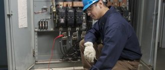
- A visual inspection of the grounding conductor contacts is carried out. Special devices - thermal imagers - are effective when searching for a “bad” contact; they quickly allow you to detect a problematic connection.
- Welding joints are tested for strength by applying mechanical load.
- All grounded structural elements are tested for the presence of metal bonds.
- Checking the presence of electric current on grounded elements.
- The results obtained are recorded in a special protocol.
The given measurement technique has proven its effectiveness.
How is metal communication checked and why is it needed?
When installing and servicing electrical installations, due attention must be paid to measuring the metal connection of grounding lines; to ensure proper functioning, it must be good enough.
Metal bonding characterizes the amount of resistance between the transition contacts of grounding bars and wires. Measurement and verification are the work of specialists from electrical laboratories.
Let's figure out what results a metal bond measurement should give.
Grounding is the basis for safety in electrical installations and outlets. All electrical devices and apparatus must be grounded.
This is necessary in order to avoid electric shock in an emergency.
Checking the metal connection is necessary in order to make sure that all ground lines are in good contact.
The results of the test are recorded in the metal bond measurement protocol. You can see a sample of how to fill it out in the photo below. After that, conclusions are drawn about the general condition of the grounding contacts and, if necessary, problems are eliminated.
Maintaining normal metal communication allows you to:
- Avoid electric shock to both electrical workers and others.
- Eliminate hot contacts, reduce the risk of fire.
- Reduce energy leakage (heating of contacts).
We have looked at why this procedure is needed, let’s find out how it is carried out.
Test method
Contact with the main grounding bus can be bolted or welded. Checking metal connections requires an accurate instrument - a milliohmmeter, capable of measuring values of 0.01 Ohm and more accurate, but not vice versa.
The measurement is carried out with a multimeter, if the latter meets the accuracy and sensitivity class. Devices must be verified.
It will not be possible to check with a regular dial; it will show the presence of a contact, but its quality will remain unknown.
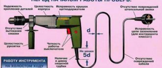
Checking and measuring metal connections begins with an external inspection of the entire installation, focusing on:
- Presence of breaks in grounding buses and wires. They can crack, tear, be destroyed by corrosion, etc.
- Quality of bolted connections. All bolts must be securely tightened, and the bars and cable lugs must not move, i.e. should not move under any force applied.
- Quality of welded joints. They are additionally tapped with good, but not too strong, hammer blows. This is done to detect cracks, the main thing is not to damage serviceable components.
How is the check performed? Each metal element of the structure must be grounded:
- racks and metal frames;
- load-bearing elements;
- marching stairs;
- lifting mechanisms;
- trays in which the wires are located;
- cable galleries;
- electrical panels;
- welding stations;
- panel doors and so on.
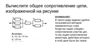
In order to measure resistance, the first probe is placed on the main grounding bus, usually it is marked with green paint with short yellow stripes, and the second probe is placed on the metal connection element with which they plan to measure. There must be a minimum number of connections from the final node or mechanism to the main gearbox.
The resistance of one transition contact should be 0.01 Ohm, its permissible excess is 20%.
If there are several transition contacts from the element being measured to the main ground bus, then their total resistance should be no more than 0.05 Ohm.
If the measurement results differ from the standard values, the contact should be improved.
For bolted ones - either just broaching, or disconnecting, cleaning adjacent planes and broaching, bringing the resistance up to standard, if the previous did not help.
If metal elements are connected not by buses, but by a flexible wire, you should also check the wire for a break, because the resulting metal bond resistance in this case increases. Welding connections must be restored.
After these procedures, you need to check the resistance again.
The standards for metal bond measurements and their results are discussed in detail:
- PUE-7, section 1.7;
- PTEEE, p.p. 26, 28;
- GOST R 50571.16;
- GOST 12.2.0-75, clause 3.3.7;
Nuances
Metal bond measurements are carried out immediately after installation, right before start-up and operation, and then, at intervals of 3 years, during routine testing and maintenance. Along with the check, as well as when the season changes, when flooding and excessive humidity are possible, the insulation resistance of cables and electrical machines is checked.
It will not be possible to check the quality of the contact and measure its contact resistance using a simple household multimeter, such as DT830 and the like.
In the region of low resistances, they either do not measure at all (up to tenths, but not hundredths of an ohm), and the resistance between the probes alone reaches 1 ohm, and sometimes exceeds.
There is no need to talk about accuracy here.
Sometimes, to measure the quality of a contact, instruments are not needed, since its destruction is obvious. In extreme cases, it comes to the point that you can measure its temperature with your hand; if it gets hot, then it needs preventive maintenance and subsequent measurements and testing with a milliohmmeter.
READ MORE: Lightweight, cheap DIY vice
Checking metal communications is very important for the life safety of enterprise employees and house residents.
Due to poor grounding in sockets or its complete absence, there is a possibility of potential appearing on the device body.
And when a person touches it, either electrical injury or something irreparable will occur. We hope the information provided was useful and interesting for you!
Rules and regulations
According to the PUE standards, grounding conductors, as well as those used for potential equalization, must be reliably connected to ensure continuity of the grounding circuit. In this case, a welded connection is prescribed for steel conductors; other methods of contact are allowed only if there is protection from the destructive effects of the air environment. When using bolted connections, appropriate measures must be taken to prevent the contact connection from loosening.
All connections between the grounding circuit and the grounded device must be located in such a way that they are easily accessible, since inspection must be carried out to check the continuity of the electrical connection. The exception to this rule is sealed contacts.
The Rules also indicate that contact with grounding devices can be made by bolted or welded connections. If electrical installation devices are subject to strong vibration or are frequently moved to another location, then a flexible protective conductor is used.
More detailed information about the rules and regulations can be obtained from the PUE (p. 1.7.).
The influence of metal communication on energy saving
High transient resistances are not only a threat to human health and life, but also a constant consumption of electricity. Experts have calculated that with a grounded case, a 24-amp safety switch and a resistance value of 10 ohms, more than 116 kW per day will be lost in case of a leak into the ground!
With these parameters, the machine will not work; the housing will pass current, posing a serious danger to any person who touches it. In this case, the contact itself will begin to heat up, causing an increase in temperature in the insulation and nearby plastic parts. All these are risks of spontaneous combustion. The meter will continue to accumulate kilowatt-hours, spending money to nowhere. And this will continue until someone pays attention to the characteristic burning smell or the metal body electrifying.
Of course, an exaggerated transient voltage value was used for illustration purposes. In practice, it is much smaller, but there are dozens, or even hundreds, of “breakdown” locations within one building. Together they provoke serious losses, not to mention the risk of damage to other property.
That is why it is important to regularly measure transition resistances when grounding using a microohmmeter, as well as monitor the condition of contact connections using a thermal imager or pyrometer. In places where thermal indices have been exceeded, “breakdowns” should be eliminated and metal connections should be established
Periodicity
According to the standards of PTEEP and PUE, metal bond tests are carried out according to a schedule determined by the technical department of the facility. As a rule, in this case the following table is used. 37 clause 3.1 of PTEEP, which establishes the following frequency of measuring metal bonds:
- In premises and objects belonging to a high hazard category, measurements of transient resistance in grounding circuits must be carried out annually, in other circumstances - at least once every three years.
- For elevator and lifting equipment – 1 year.
- Stationary electric stoves – 1 year.
As a rule, checking metal connections is carried out in conjunction with other types of electrical measurements (insulation resistance, checking the integrity of electrical wiring, etc.).
In addition, mandatory metal bond measurements are carried out in the following cases:
- If electrical equipment has been repaired or re-equipped.
- When testing new electrical installations.
- After installation work.
Recording the results of metal communication measurements
After carrying out the necessary measurements of the metal connection, the Customer receives a protocol containing the test data and indicators recorded by the engineers. The document includes the following information:
- Marking and designation of electrical equipment that has been checked by a specialist.
- The number and location of the investigated contact elements.
- The result obtained when the device measures a section of a grounded circuit.
If discrepancies are detected with the standard indications of the PUE or a violation of the metal connection of the equipment, an appendix is issued to the main document, which indicates the detected defects.
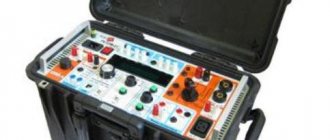
Measuring instruments
Considering that metal bond measurements are carried out at the level of hundredths of an ohm, conventional measuring instruments, for example, multimeters, are not suitable for this purpose. When measuring ground resistance, more accurate instruments are used that are sensitive enough to measure low-level resistance.
Metrel MI3123 Ground Tester
Most of these devices are equipped with additional functions, for example, the Metrel MI3123 shown in the figure can also measure soil conductivity and leakage current.