What is needed for work
A soldering gun, also called a hot-air soldering station, is a multi-component tool with a large number of functions for repairing modern devices. It allows you to solder SMD components, capacitors, LEDs and other parts. The same applies to BGA-type chips, which make installation more dense. Today, almost every electronic component in modern devices is made in this way.
To solder SMD components, you need the following materials and devices:
- actually, the hair dryer itself;
- attachments for it;
- flux with solder paste;
- copper braid;
- some kind of device for prying up parts (tweezers, for example);
- medium-soft brush;
- lens;
- a soldering iron with a thinner tip compared to a standard one;
- stencil for “rolling”.
To work competently with a soldering gun means to be careful, have angelic patience, and be extremely careful.
Requirements for soldering equipment
For microcircuits, the acceptable temperature range is from 190 to 240 degrees. If the temperature is higher during soldering, then you risk overheating the chip, which will cause it to become inoperable. As a result, you will not only waste your time, but also lose an expensive part.
Another characteristic that soldering equipment must have is a stable heating area and jet.
Compared to a miniature soldering station, a hair dryer is able to maintain the required heating temperature in a stream of air, which remains so even with small changes in the distance between the device and the printed circuit board. When using a hairdryer, the heating area remains stable. It is determined by a direct flow of air. But at the edges of the jet, the heating temperature turns out to be below the minimum permissible, which is why it not only cannot harm the circuit parts, but also melt the solder.
A soldering gun that creates an unstable cone-shaped stream of hot air that expands as it approaches and contracts as it moves away will allow you to get the job done quickly and efficiently. Often, craftsmen who decide to make a hair dryer for soldering microcircuits with their own hands do not take into account the stability of heating and the uniformity of air flow, which makes it inconvenient for them to work.
Another requirement is safety and ease of use.
Speaking of safety, we mean that you will not make fundamental changes in the design of an electrical appliance, violating the factory design diagram of the connection nodes, especially if they have an operating voltage of 220 V. To be on the safe side, you can connect a home-made soldering device without directly, but through a transformer, which can be made from a computer power supply. This way you will protect yourself from serious troubles.
As for ease of use, this means that the device should be obedient in your hands and not require much effort to perform certain manipulations. The hairdryer should be designed in such a way that your second hand remains free. Then, with its help, you will be able to hold tweezers or perform other necessary actions.
Sequence of actions using the example of an SMD component
Let’s say that on the working printing surface of the electronic unit being repaired there is a burnt-out SMD box that needs to be dismantled. To remove it and install a new one, you need to select a compact nozzle for the hair dryer and prepare flux.
The temperature regime on the soldering hair dryer is set within 345-350 degrees using a regulator. Then they apply flux to the part to be replaced, and begin to slowly “warm up”.
The air pressure during the process should not be too strong, otherwise there is a risk of blowing away nearby elements. The culprit of the breakdown continues to be heated until the solder begins to melt, which will be immediately noticeable.
It may take about three minutes to warm up, and this is normal, there is no need to rush. If the solder persists for a long time, you need to add 5 degrees.
After the solder has liquefied, carefully dismantle the SMD part. During the process, it is important not to knock down the neighboring components, since they have probably lost stability due to the melting of the solder holding them in place.
Upon completion of the operation, the copper braid must be used to clean the “spots” (contact pads), then provide small bumps in the same places with solder paste or solder.
A serviceable smd is placed in the old place with a minimum amount of flux. Heat the part with a soldering hair dryer until the solder shines brightly, spreading over each of the contacts.
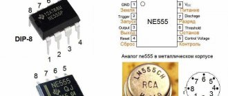
Hair dryer device
A soldering station in the form of a hair dryer is usually used to melt or soften a plastic product, thin metal or tin. It is possible to supply high-temperature air only after it has passed through a very hot spiral. In order to create a soldering gun yourself, you will need to carefully familiarize yourself with its design.
Components of the soldering gun design:
- heater (special housing-tube);
- a vane fan or pump that supplies air flow;
- handles, switch, temperature sensor.
Sometimes you can also use special nozzles that allow you to change the flow of the jet.
Control circuit
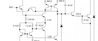
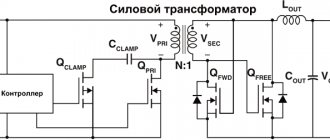
Let's consider a circuit diagram for controlling a hair dryer, which is powered from a single source. This fact greatly simplifies the operation of the device.
The main element of this circuit is a parametric type stabilizer, which is assembled on transistor VT1, zener diodes D5, D6, D7 and resistance R1. This device guarantees the stability of the soldering gun voltage, while the source voltage may change due to air flow adjustments.
In order to change the fan speed, switch SA1 is used, which has two positions - 8V and 12V.
Zener diode D8 and fuse FU1 provide protection against extreme voltages. When the voltage rises to 15 volts, the diode opens and the fuse blows.
Let's figure out why it is best to use a parametric stabilizer in this design. When using alternating current, voltage peaks can reach extreme values. This will damage the microcircuit. It's quite easy to give an example. At a voltage of 30 Volts (alternating current), the peak will be:
Final assembly
The assembly of a homemade soldering station is carried out in several stages. First, assemble the heating element. It consists of 5 spirals and a ceramic insulating tube. The ceramic tube can be borrowed from a TV (the delay line contains just what you need).
Then the spiral of the heating element is wound. It is best to wind the future spiral using a drill.
One of the most complex design parts is the heater housing. It is usually assembled from a glass, a pipe and a washer.
Surprisingly, a glass with an outer diameter of 1.65 cm fit perfectly from an old lithium-ion battery. It is in such cases that the chemical filling is placed. Before disassembling the laptop battery, it should be completely discharged. For this, low-resistance powerful resistors are used.
You can use a 1 liter soda bottle as the body of the soldering gun. The bottle was selected based on the size of the fan.
Features of working with BGA chips
When soldering BGA type microcircuits, the same temperature range is selected from 345 to 350 degrees, ensuring moderate air pressure to prevent blowing off the “neighbors”. During operation, the soldering gun should be held at an angle of 90 degrees with respect to the board. To avoid failure of the chip, you should not heat it only in the center; it is better to go around the mounting element around the perimeter.
After 1-3 minutes have elapsed, you can try to slightly lift the chip above the board using tweezers. If the chip does not budge, the solder is still hard. To avoid damage to the conductive paths of the board, you need to use the regulator on the hair dryer to “throw on top” 5 degrees of temperature and continue heating.
Requirements for soldering equipment
For microcircuits, the acceptable temperature range is from 190 to 240 degrees. If the temperature is higher during soldering, then you risk overheating the chip, which will cause it to become inoperable. As a result, you will not only waste your time, but also lose an expensive part.
Another characteristic that soldering equipment must have is a stable heating area and jet.
Compared to a miniature soldering station, a hair dryer is able to maintain the required heating temperature in a stream of air, which remains so even with small changes in the distance between the device and the printed circuit board. When using a hairdryer, the heating area remains stable. It is determined by a direct flow of air. But at the edges of the jet, the heating temperature turns out to be below the minimum permissible, which is why it not only cannot harm the circuit parts, but also melt the solder.
A soldering gun that creates an unstable cone-shaped stream of hot air that expands as it approaches and contracts as it moves away will allow you to get the job done quickly and efficiently. Often, craftsmen who decide to make a hair dryer for soldering microcircuits with their own hands do not take into account the stability of heating and the uniformity of air flow, which makes it inconvenient for them to work.
Another requirement is safety and ease of use.
Speaking of safety, we mean that you will not make fundamental changes in the design of an electrical appliance, violating the factory design diagram of the connection nodes, especially if they have an operating voltage of 220 V. To be on the safe side, you can connect a home-made soldering device without directly, but through a transformer, which can be made from a computer power supply. This way you will protect yourself from serious troubles.
As for ease of use, this means that the device should be obedient in your hands and not require much effort to perform certain manipulations. The hairdryer should be designed in such a way that your second hand remains free. Then, with its help, you will be able to hold tweezers or perform other necessary actions.
Heating from below
This technique is not only useful when working with a soldering gun, but also increases the convenience of soldering.
The board is secured with a clamp, the temperature is set to 200 degrees and warmed up for five minutes, after which they begin to work as usual.
Using thermal tape, you can shield nearby elements.
After removing the chip, the contacts are cleaned with the above braid. Do the same with the board.
All procedures must be carried out carefully to prevent damage to the circuit. If you don't have copper braid on hand, you can remove the solder using a soldering iron with a thin tip.
Criterias of choice
To choose the most suitable soldering gun for you, you need to understand the main tasks that you plan to solve with its help. One of the most important criteria is the melting temperature of the solder, which is used to attach radio components to the board.
So, all solders can be divided into low-melting or soft solders with a melting point from 145 to 400°C and refractory or hard ones with a temperature of more than 400°C. Accordingly, if you will solder low-melting lead-tin solders, you will need a soldering hair dryer with an operating temperature range from 100 to 300 °C. If you want to get a universal device, then it is better to choose a model with an upper limit of 500 - 800°C. Also evaluate the temperature adjustment step, as this will directly affect the convenience of obtaining the desired parameter.
The shape and size of the nozzle determines the heating area for soldering. Thus, thin round holes provide a targeted impact of a soldering gun on each leg; square holes do an excellent job of immediately covering all pins of a microcircuit or controller.
Depending on the parts being soldered, the power of the soldering gun is selected. So, to work with computer boards, you need to choose models from 100 W and above. For particularly powerful elements, industrial hot air dryers with a power of up to 1.7 kW are used.
Review of TOP 7 popular models
Today, the market offers a fairly wide selection of soldering equipment, so in this article we will look at the most popular models. As candidates for the role of frequently purchased soldering stations, an important component of which is a hot air gun, we will present both foreign and domestic devices.
Rice. 3. Soldering gun LUKEY-868
1. LUKEY-868 - a popular model from a Chinese manufacturer has a power of 750 W and is capable of adjusting the temperature from 100 to 480°C. It is equipped with a display and control panel that allows you to adjust operating characteristics. Additionally equipped with a classic soldering iron and separate stands for a hair dryer and tip. The advantages of such a soldering gun include:
- Relatively light weight - only 1 kg, compared to other analogues;
- Does not require time to warm up;
- Comes with 3 replaceable nozzles.
Rice.
4. Hot air soldering station Weller WHA 900 Set 2. Weller WHA 900 Set - refers to professional soldering units made in Germany, equipped with a turbine for pumping air flow. It has a power of 700 W and is capable of producing operating temperatures in the range from 50 to 550 ° C, the model’s productivity is 50 l/min. The advantages of such a soldering gun include:
- High accuracy of setting operating parameters;
- Large selection of replaceable nozzles;
- It has a foot switch, which greatly simplifies the soldering process.
Rice.
5. Hot air soldering station, digital ZUBR 55350 3. ZUBR 55350 – a soldering station with a domestically produced hair dryer, designed to implement any tasks within the temperature range from 100 to 500°C. The power of the device is 650 W, and the air flow capacity reaches 120 l/min. Digital adjustment from the control panel is displayed on an electronic display, which allows you to clearly monitor the entire process. The Zubr soldering gun has the following advantages:
- High sensitivity of adjustment - the temperature can be set in steps of up to 1°C.
- The hair dryer features a ceramic heating element that reaches the desired temperature in a matter of seconds.
- Has antistatic protection to prevent damage to radio elements.
Rice.
6. Hot air soldering station Quick 857DW 4. Quick 857DW is a soldering station from a Chinese manufacturer, the rated power of the device is 580 W, the temperature range is from 100 to 450 ° C. The soldering gun is capable of producing an air flow of 100 l/min. The model is powered from a 230 V household network. The weight of the product is as much as 2.4 kg, which somewhat complicates its transportation.
The advantages of such a soldering gun include:
- Four replaceable attachments to expand the functionality of the device;
- Equipped with protection against static charge accumulation;
- Convenient temperature adjustment.
Rice.
7. Soldering hair dryer ELEMENT 858 5. ELEMENT 858 - is one of the most affordable and easy-to-use soldering stations with a hair dryer. For control, it is equipped with two control knobs that allow you to change the temperature range from 100 to 450°C. The air flow is forced by a turbine, the available power is 650 W. The performance of the soldering gun reaches 120 l/min, but to obtain the nominal temperature you must wait a few seconds.
The advantages include:
- The optimal combination of price and quality for beginner radio amateurs;
- Simple and clear adjustment;
- Good air flow.
Rice.
8. Soldering station with digital control MEGEON 00686 6. MEGEON 00686 is a domestic model of a soldering station with a soldering hair dryer, characterized by an average power consumption for heating of 500 W. The maximum temperature can reach 500°C. The weight of the model is 2.5 kg, powered by a 230 V network. The advantages of the model include a digital display and the ability to adjust both thermal parameters and air flow speed.
Rice. 9. Hot air soldering station with a hair dryer-pencil METCAL HCT2-200
7. METCAL HCT2-200 – a soldering station designed for fine soldering, equipped with six nozzles for a hair dryer. Consumes 200 W of power from the network, operates in a temperature range from 100 to 450°C. The weight of the device is 2.2 kg.
Reballing procedure
To carry out reballing, the chip is placed in a stencil and secured with specialized electrical tape. Apply solder paste on the back side with a finger or spatula, then set the hair dryer to a temperature of about 300 degrees and begin to warm it up. After the characteristic shine from the molten solder paste appears, allow the solder to cool completely.
To free the stencil from the chip, remove the electrical tape and heat the stencil to approximately 150 degrees; at the end of the procedure, the part should be free. It happens that it is impossible to immediately remove a part from a Chinese stencil, so it may be necessary to carefully hook it.
During reverse soldering of the microcircuits, the risks are assessed and the chip is laid out the required number of times to ensure an exact match of the heels and balls. Then they set the temperature on a soldering hair dryer to 330 to 350 degrees and heat until the melted solder allows the chip to fall into place on its own.
A soldering station is an indispensable tool for an electronics engineer. Usually the station comes with both a soldering iron and a hair dryer. If you learn how to use them, then almost any soldering will seem exciting and not very difficult.
A special feature of the stations is temperature control. You need to immediately remember an important rule - avoid temperatures above 400 °C or more. Many beginner (and even experienced) radio amateurs neglect this. These are critical values for microcircuits and boards.
Solder melts at approximately 180 to 230°C (lead-containing solders) or 180 to 250°C (lead-free). This is far from 400 °C. Why then set the temperature high?
Design of a soldering iron hair dryer
Based on the fact that it is necessary to obtain a stream of hot air, the design of the soldering device is formed. A homemade soldering hair dryer made with your own hands consists of the following elements:
- heater;
- heater insulation;
- fan;
- nozzle;
- hair dryer body;
- body handle;
- control circuit;
- soldering iron holder.
Heater
Nichrome wire in the form of a spiral is used as a heater. To do this, you can use a simple spiral from an old household hair dryer. The spiral must be of such a diameter that there is a gap between the heater and the air duct body.
When winding a spiral, one end of the wire is threaded inside the heater, so that two ends of the conductor come out to connect to the power source. To insulate the spiral, it is wrapped in mica.
Heater insulation
In order to avoid heat loss, the heater spiral is insulated from the heater body. One of the insulation options is mica. Mica reliably isolates the spiral from the air duct tube. The fragile material is glued onto fiberglass.
Fiberglass is a good heat insulator. To glue mica to fiberglass, use rubber glue or the universal Moment product. In some cases, mica is glued onto paper. Subsequently, the glue and paper will burn out, but the mica will remain in the form of an insulating tube.
Air duct
The shells of various radio components, for example, resistor or resistance housings, are used as the air duct (casing) of the heater. You can use any steel tube of suitable diameter. The edges of one end of the tube will have to be rolled. This is necessary to ensure that the nozzle is securely held in the outlet of the tube.
For example, take an old C-5-5 resistor and carefully remove the rolled edge on one side of the shell with a file. The inner filling is removed and the air duct tube is ready.
Important! Following the advice of the “masters,” a ceramic or quartz glass tube is used for the air duct. If flux accidentally gets on the surface of these materials, the tube is destroyed. Therefore, the best material for this part would be steel.
Fan
It is quite possible to use a cooler from a computer operating unit as an air blower. The fan has dimensions in terms of 40 x 40 mm, which must be taken into account when forming the body of a homemade hair dryer.
Small fans can be found in old household hair dryer housings. In this case, you need to choose a device that is acceptable in terms of power and dimensions.
Nozzle
The nozzle is designed to concentrate and focus the air flow. To make the element, a metal washer is taken. The ring is deformed with a core so that it takes the shape of a bowl.
The nozzle is placed in the outlet of the air duct. The washer rests with its edges on the curved edge of the tube and does not fall out.
Hair dryer body
The body of the soldering iron can be cut from a tin can. Tin sheet 0.3 mm thick is an ideal material for making a hot air gun with your own hands. Bends are made at the joints of the sheet metal. Small holes are drilled into them, screws are inserted into them and tightened with nuts.
Note! The use of tin is not a dogma. For homemade cases, any heat-resistant material is used. This can be construction plywood, textolite and even laminate.
The main requirement for the layout of the parts of a closed hair dryer chamber is its tightness. All joints of housing elements must fit tightly to each other. This is necessary to ensure the required pressure of the air flow pumped by the fan. The camera elements are connected with screws. Due to the high temperature inside the case, glue is not used.
Case handle
According to the advice of amateur craftsmen, the body of a disposable plastic syringe is well suited for the pen. The syringe has ears in which holes are drilled. The same holes are made in the body of the hair dryer. The handle is screwed to the hair dryer with screws, nuts and washers. To ensure reliable fastening, spring washers – “grovers” – are placed under the washers.
Control circuit
To solder a microcircuit with your own hands using a homemade hot air gun, you need a unit for adjusting the operating modes of the soldering device. These are two modes: setting the desired heater temperature and adjusting the number of revolutions of the fan blades.
Read also: Drill attachment for cutting round holes
The basis of the control unit is a transformer with two secondary windings. Instead of a transformer, you can use a power supply from an old computer or fluorescent lamp ballast. There are many options, as long as the heater and cooler resistances match the power sources. To adjust the operating modes of the hair dryer, two variable resistors are included in the control unit circuit, the control knobs of which are located on the surface of the unit body.
A detailed version of the control unit diagram for a hot air gun for soldering microcircuits with your own hands can be found in Internet publications.
Soldering iron holder
The holder is an important part for a soldering device. The fact is that a simple hair dryer holder frees the technician’s hands for positioning the wiring diagram in front of the soldering iron air duct, as well as for removing and installing radio components on the board.
The stand is made massive to prevent the entire soldering structure from tipping over. To do this, use a sheet of metal 100 x 100 mm and at least 20 mm thick.
The holder is made of tin, bending it to the size and shape of the hair dryer handle. The holder is placed on the stand with the input groove facing up. The bend of the tin element is secured to the stand with screws through drilled holes.
Additional Information. A soldering iron can be a mobile device. In this case, a frame with clamps is made in which the board being processed is fixed in a vertical position.
Educational program for beginners
To desolder a part from a board, you need to make sure that the contacts are heated until the solder melts (approximately 230 °C). The main mistake beginners make is to immediately heat the place where they are soldering to 300 - 350 °C.
For example, you need to desolder a microcircuit from a board using a Lukey 702 soldering station.
Many radio amateurs and electronics engineers set heating parameters above 300 °C.
At the first moment, the part is exposed to about 200 °C. The contacts and the surrounding area of soldering work are at room temperature. The heating of the part reaches 300 °C, but the contacts have not yet reached 200 °C.
The microcircuit experiences a critical temperature of 350 °C. Meanwhile, the surrounding soldering area is heated unevenly, even if the hair dryer is evenly moved across the soldering area. A noticeable temperature difference appears at the contacts of the part.
400 °C and the microcircuit begins to fry.
A little more, and it will unsolder due to the fact that the contacts have practically heated up until the solder melts. But this happens because the board has warmed up. And in this case, it happened unevenly. High temperatures lead to thermal breakdown of the microcircuit and it fails. The board bends, turns black, and bubbles appear due to boiled PCB and its components.
This soldering method is very dangerous and ineffective.
Characteristics and operating principle
Do-it-yourself gasoline generator
You can consider the characteristics of soldering stations by dividing soldering methods into two groups: lead and lead-free.
Devices belonging to the first group have a module in their structure that makes it possible to set the required temperature level of the tip. Such models are made both as devices that use electricity for their operation, and as stations based on an alternating magnetic field (induction type). A high level of heat transfer and automatic selection of power for individual elements are the main advantages of induction stations.
To perform non-contact soldering, the second type of soldering installations is used. These are stations based on infrared and thermal air influence on the soldering area.
Summarizing the characteristics of the devices, the following parameters are distinguished:
- heating element material: nichrome or ceramic;
- heating rate;
- temperature adjustment range;
- installation power;
- supply voltage.
Also, the main design features include shape, dimensions and weight.
How to desolder a microcircuit
How do you solder parts without damage?
It is necessary to analyze the soldering area and equipment:
- Estimate the thickness of the board. The thicker the board, the more difficult and longer it takes to warm it up. The board consists of layers of tracks, masks, pads and many metal parts that are very heat-intensive.
- What's nearby? To avoid damaging surrounding components, they must be protected from temperature. The following will cope with this task: thermal tape, aluminum tape, radiators and coins.
- What is the ambient temperature ? If the air is cold, the board will have to be heated a little longer. Of particular importance is what is located under the board. No need to solder on a metal plate or on an empty bench. A wooden board or a set of napkins works best. And at the same time, the board must be in the same plane, without distortions.
- Equipment. Many soldering stations are sold without calibration. The difference between the temperature shown on the indicator and the actual temperature can reach either 10 °C or 50 °C.
Power supply diagram
Schematic diagram of a UPS from a Kenon printer
If the power supply is in working order, the most important thing is to avoid the temptation of improvement and radical modifications. All you need to pay attention to is the SMD resistor R25 with a nominal value of 18 kOhm. First, unsolder it and solder two soft stranded wires in insulation 15 cm long onto the contact pads. And don’t touch anything else on the board.
Modification of the power supply for the cooler
But with this particular power supply, due to its recent malfunction, we had to deal with it less delicately - to be sure and fully understand its real functioning, we had to remove not only the SMD resistor R25, but also the trimming resistor VR21 and the output zener diode ZD21.
Useful: Staircase lighting timer Checking power supply with a multimeter
The place of the trimmer was taken by a 4.7 kOhm variable, and instead of an 18 kOhm SMD resistor, a 22 kOhm variable resistor was installed. Having connected the electric motor of a hand drill to the load and driven it heartily, I set the 4.7 kOhm variable to such a position that the 22 kOhm variable resistor in the extreme left position of the slider produced 5 volts at the output, and in the extreme right position almost exactly 24 volts.
How to solder with a hairdryer correctly
It is necessary to cover all small components that are vulnerable to overheating with protection.
In this case, aluminum tape is used. It protects components well from temperature and holds the board components tightly. However, it adds heat capacity to the soldering area. Thermal tape also protects well, but sticks to the board less well.
The board is placed on a material that has the least heat capacity and slowly releases temperature to the environment. You can use, for example, a wooden plank. And at the same time, the soldering area should not be inclined.
It is best to apply flux to the contacts. It distributes heat well compared to heated air, but you should not add too much of it. It may boil, hiss, or interfere with soldering.
The first step is to warm up the soldering area. The hair dryer is set to about 100 °C and maximum air flow.
It is necessary to warm up both the part itself and the surrounding soldering area with contacts in a circular motion.
Next, after about a minute, you should gradually increase the heating.
The difference with the contacts will be small. Thus, within a few minutes, increase to 300 °C.
Steps of about 20 - 30 °C for every tens of seconds.
The simplest installation from the cigarette lighter
The cigarette lighter, which is controlled by 12 volts of the car battery, is capable of creating temperatures that allow soldering BGA controllers and various SMDs.
Many designers believe that such a station provides a heating ring (the so-called “ring”), which will repeat the projection of the heater. However, the test on paper showed absolutely uniform heating, without rings. This means that modifying the cigarette lighter makes sense.
During the test, it was clear that the color of the paper evenly stained the sheet from the center towards the edges. Pure infrared heating plus convection without any blowing - and the cigarette lighter turns into an excellent soldering device.
Soldering stations from the cigarette lighter, compared to soldering hot air guns, are quiet, do not produce any jets or kickbacks, soldering occurs calmly. Ten volts of alternating current, supplied from a suitable transformer, is quite enough to remove a 100-socket processor from the motherboard at a distance of 1-1.5 cm.
Read also: How to make a case for an angle grinder with your own hands
The second contact of the spiral must be brought out into the housing tube and fixed with high-temperature sealant. The construction will require brass soldering. It can be done using a gasoline torch, a strip of brass and borax. The distance at which soldering is carried out reaches a maximum of 1.5 cm. This design has proven itself very well.
If you come up with a handle, a body and a holder, and this is quite simple, given the body of the cigarette lighter, then this device will be many times better than a regular Chinese-made soldering iron.
How to understand that a part is already soldered
A glare appears on the contacts. Using tweezers, gently push the chip. If it moves easily and smoothly from side to side, then it can already be removed; if not, we heat it further.
This technique must be individually adjusted for each soldering and soldering station. For example, sometimes you will have to heat the board longer, and sometimes about 240 °C will be enough. The soldering method depends on the case.
DIY soldering station diagram, element base
The key tool of a soldering station is the soldering iron. If, when assembling the station yourself, you can use some elements removed, for example, from household appliances that have expired. Then the soldering iron should be new without any dispute. Many craftsmen prefer Solomon products and some others.
Soldering station diagram
After selecting a soldering iron, you can begin to select a diode bridge for the electrical circuit and transformer. In order to obtain a voltage of 5 V, a linear stabilizer with good cooling is needed. As an alternative, you can consider using a transformer that has a winding available that is necessary to service the digital unit.
A schematic diagram of a homemade device can be found on specialized forums.
Alloy Rose
To reduce the risk of overheating, Rose alloy can be used. It will help reduce heat to 120 °C. In this way, you can remove the part from dangerous and sensitive areas. Just add a couple of solder granules and a little flux.
After tinning the contacts, the part is easily desoldered. You need to carefully desolder the contacts; they can easily be damaged due to sudden movement. The resulting solder must be removed from the board. It is very fragile and not suitable for use.
Combined method
Another very effective technique. If during soldering the part is poorly soldered or does not desolder, this is a consequence of low-quality solder, flux, or insufficient heating of the board.
To do this, while working with a soldering iron, you need to help from above with a soldering hair dryer. The hair dryer should be set to 200°C. This way, heating will occur faster, and the temperature at the contacts will stabilize, and the surrounding air will absorb less heat.
In what cases will soldering with a hairdryer not work?
A soldering gun usually reaches a power of no more than 500 W. The lower the power, the less the board area can be heated.
A massive board requires bottom heating. Most often this is a stove that heats up to 100 - 200 °C. The printed circuit board will be heated evenly. And use a hair dryer to bring the solder to melt.
You can also use a hair dryer. It has a larger nozzle and its power can be up to 3000 watts. However, a hair dryer is not a solution either. Due to the fact that only the part and a small surrounding space around it are heated, after soldering the board is deformed due to the high heating difference, thereby tearing off the leads from the pads (this is especially true for large BGA parts).
The need to dismantle radio elements arises in several cases:
- Dismantling the faulty element;
- Incorrect installation of the radio component;
- Soldering from the donor board due to the lack of a new microcircuit.
In all these cases, except for the first, the main conditions are maintaining the integrity and working condition of the soldered part and the integrity of the printed circuit board.
To carry out this work, it is necessary to observe accuracy and simple rules that were developed back when most of the range of radio components was in short supply. The urgent question was how to remove an expensive microcircuit from the board without damaging it.
Hairdryer from a soldering iron
Soldering gun diagram. Before you make a soldering gun with your own hands, you should:
- think over a device for air supply;
- assemble a special heating element;
- equip the equipment with thermocouples;
- think over a system for monitoring the current temperature of the equipment.
When considering how to make a soldering iron from a regular soldering iron, you should take into account all the subtle points so as not to expose yourself to excessive risk.
The main criteria that a soldering iron-based thermal device must meet are:
- temperature adjustment;
- normal heater power;
- safe compressor.
It is recommended to install a supercharger for a DIY soldering station in accordance with current electrical safety regulations. Connecting the equipment in this way will ensure that there is no interference in the electrical network.
What do you need to create a hair dryer from a soldering iron?
When creating a hair dryer for soldering with your own hands, you should prepare:
- a regular old soldering iron running on AC power;
- a quartz tube to create a hair dryer air flow heating chamber;
- a halogen lamp for spotlights for heating the air and melting flux with a hairdryer;
- nichrome wire up to 0.7 millimeters thick;
- thermostat;
- soldering gun fan.
Schematic diagram of a soldering gun. All equipment must be connected to specially prepared connectors at the soldering station, the pinout of which depends on the manufacturer of the soldering equipment.
https://www.youtube.com/watch?v=3zE-HDdz2Xs
The process of assembling a hair dryer from a soldering iron
A homemade hair dryer for soldering microcircuits from an old soldering iron is assembled in several stages:
- Laying a homemade spiral of nichrome wire inside a quartz tube.
- Connecting the spiral to the power wire.
- Threading a thermocouple wire to regulate the temperature of the filament.
- Insulation of the device using a layer of tube wound on a quartz tube.
- Installing a tube in the handle of a soldering iron instead of a tip.
- Centering the tube by wrapping it with asbestos cord.
- Clamping the front tube outlet using a clamp.
- Threading a hose to supply air flow.
- Connecting a compressor that creates an air flow.
It is better to place the temperature regulator of the heating source on the body of the heat gun.
The operating principle of a hot air gun based on a soldering iron is as follows:
Soldering gun - drawing for manufacturing. Unfortunately, this method of making a thermal hair dryer has a lot of disadvantages.
The disadvantages of a hot air gun made from a conventional soldering iron include:
- difficulties with temperature calibration;
- The air flow force is adjusted by pinching the air duct;
- the inability to adjust the heating intensity in most conventional soldering irons;
- labor intensity of work;
- poor thermal insulation of the device.
In most cases, making a heat gun from a soldering iron is not justified. Remaking an inexpensive construction hot air gun is a much more efficient method of making a hot air gun for soldering micro components.
Chip types
The wide variety of microcircuit packages has led to the fact that soldering techniques began to differ. Previously, the most widespread were microcircuits with pin pins for mounting into holes on a printed circuit board. Subsequently, with an increase in the degree of integration and the widespread use of automated soldering lines, surface mount elements with flat or ball leads began to be used.
ICs (integrated circuits) with solder pins are typically DIP and SIP packages with two and one row of pins, respectively.
Surface mounting ( SMD ) allows installation of ICs with pins of the following types:
- Flat leads brought outside the housing - SOIC, SOP, QFP (square housing);
- Flat legs, bent inward, under the body - SOJ, PLCC, QFJ;
- Ball terminals - BGA.
Each variety has several subspecies. The total number of housing types is in the dozens.
Safe work with semiconductor radio components
Before you unsolder a part from the board with a soldering iron, you need to know the following. Semiconductor elements are extremely sensitive to overheating. Also, tracks on a printed circuit board at high temperatures or when the soldering time is exceeded can peel off from the substrate or break, which is even worse.
Temperature conditions
The temperature of the soldering iron tip should be 200-250⁰С. At higher temperatures, peeling of the printed tracks and overheating of the microcircuit may occur. The same goals are set for the soldering time of one leg - no more than 3 seconds.
Note! Some sites advise for dismantling to focus not on the temperature, but on the power of the soldering iron. It is not right. Their temperatures are the same, it’s just that a less powerful one may not be able to cope with melting the solder at the pin due to intense heat removal, and a too powerful one can easily overheat the pins and the board. The best option is a 40 W soldering iron.
Many microcircuits are sensitive to static electricity. It is necessary to work with an electrostatic wrist strap on and a grounded tool.
Assembly kit
There are special kits for assembling soldering stations. One such kit offers to assemble a digital station based on the Atmega 328P controller.
Parts List:
- Atmega328p controller;
- LCD with dimensions 16x2;
- OU: LM358;
- optical isolation: MOC3063;
- mosfets IRFZ44N (2 pcs.);
- triac: BT138;
- stabilizer;
- potentiometers 10kOhm;
- trimming resistors 10 kOhm.
The kit also includes two LEDs, a 16 MHz resonator, SMD resistors and a 1 µF capacitor. Soldering work will be incomplete without switches, GX16 5 and 8 pin sockets, and a 24 Volt switching power supply.
Schematic and PCB
Thus, if you know the laws of radiophysics, making a soldering station with your own hands will not be difficult. Moreover, by selecting quality components, excellent results can be achieved.
A soldering gun, contact station and other homemade devices will last a very long time and, unlike their Chinese counterparts, will operate at the required temperature conditions.
Schematic electrical diagrams, connecting devices and pinouts of connectors
Yielding to temptation, I bought a hot air soldering gun on AliExpress. The issue price is 600 rubles. Accordingly, I began organizing the appropriate “wiring” of the device. I started with the fan control. The fan in the hair dryer is powered by a direct current of 0.25 A and a voltage of 24 volts. For this purpose, a switching power supply from a Canon K30232 printer is exclusively suitable, of which there are a great many on free secondary sale, and at a low price. And here the main convenience is not even that it is at the required 24 volts and produces quite sufficient current up to 0.7 A, but that the circuit already provides a trimming resistor, which is extremely necessary when adjusting the output voltage in the required range.
Power supply from Canon K30232 printer
I didn’t buy my own power supply, it was in stock, although it had been faulty for two years already, but when I really needed it, I managed to somehow quickly fix it.
Board design
Printed circuit boards differ in the number of printed layers and the method of installing radio components:
- Single layer;
- Double layer;
- Multilayer;
- For DIP elements;
- For SMD components.
One board can contain both DIP and SMD elements on one or both sides. Multilayer printed circuit boards, in addition to outer layers, have internal ones, which usually serve for general shielding or wiring of power circuits. Thus, the motherboards of modern computers or mobile phones have up to seven layers.
Infrared soldering station
When repairing complex circuits and motherboards (especially those with BGA components), you will need an infrared station. Chinese products are of very low quality, and a good infrared installation is quite expensive. The solution is obvious: there is nothing difficult in assembling a soldering tool with your own hands.
When assembling such a soldering device, you can invest in a budget of up to 10 thousand rubles. Despite the low cost, the station performed well during repair work related to the installation of microcircuits.
Description of design
The device consists of the following components:
- control controller;
- bottom type heating;
- top type heating.
The controller must be a 2-channel type.
The first channel is connected to a thermocouple or platinum-type thermistor. The second should simply be connected to the pair. Both channels have automatic and manual modes. The first allows temperatures to be maintained up to 255 degrees using feedback from a thermocouple or thermistor.
Manual mode allows settings in 99% ranges. The controller memory contains fourteen different types of thermal profiles: seven lead-type profiles and seven lead-free solder profiles.
For lead-containing solder, the range of maximum temperature profiles starts at 190°, and then every 5 to 220°.
For lead-free solder, maximum profile temperatures start at 225°, and then every 5 to 250°.
In cases where the upper heating element simply cannot cope and heating cannot be provided, the controller element goes into “pause” mode and waits for the desired temperature. This allows the chip to be adapted for heaters that are so weak that they are not able to follow thermal profiles.
The controllers are also used as temperature regulators for the soldering station, for example, if drying or baking solder masks is necessary. Such devices are great for maintaining temperature.
Dismantling techniques
The method of soldering microcircuits depends mainly on the type of pins, although there are universal methods.
Dismantling the microcircuit with a soldering iron
This is the most time-consuming and unreliable method. It is used only when the number of microcircuit legs is minimal. Before soldering microcircuits with a soldering iron, the tip of the tip is carefully tinned and cleaned of solder residues so that it remains only in the form of a thin film. The molten solder that surrounds the IC leg is transferred to the tip under the action of tension. By repeating the procedure several times, the leads are completely released.
Important! Before each touch of the board, the tip is cleared of solder. The touch time should not be more than three seconds. If the leg is not completely freed, you can only work on it after some time has cooled down. At this time, you can make the following conclusions.
Removing the chip using a razor blade
When working with planar elements, an ordinary razor blade will come to the rescue. For convenience, the razor blade is broken in half lengthwise. Leaning the blade close to the border of the terminal and the board, heat the scion until it melts. By inserting a blade between the leg and the board, they are separated. The blade is made of stainless steel, so solder does not stick to it.
Using dismantling braid
The special dismantling braid works thanks to the capillary effect, drawing in the molten material. You can use braided shielded cable with the same effect. The braid must be clean, without traces of oxidation. In order to improve the spreading of the melt, the braid is moistened with liquid flux.
Dismantling microcircuits using a desoldering pump
The desalination pump is a special piston that, when moving, draws in the melt, releasing the outlet. This method is suitable for working with DIP and SIP components.
Using medical needles
This method has proven to work best when dismantling ICs, especially for single-sided printed material. Double sided PCB can also be used to remove needles from syringes. When choosing a needle, you need to ensure that its inner diameter allows the leg of the microcircuit to fit freely, and its outer diameter allows it to fit into the hole on the printed circuit board. The tip of the needle is ground with a file until a smooth surface is obtained.
The needle is placed on the tip of the leg and the terminal is heated with a soldering iron. After the solder has melted, the needle is inserted into the hole of the board and smoothly rotated around the axis until the tin solidifies. After this, the needle is removed from the stem, which is now completely free. The needle material (stainless steel) is not tinned, so rotation around the stem is only necessary to make it easier to remove it from the hole.
Use of alloy rose
Using a rose alloy, you can desolder all the terminals of the IC at the same time, due to the fact that the low-melting alloy spreads between the terminals and evenly and simultaneously transfers heat to all of them from the heated soldering iron tip. After complete heating, the part is carefully removed from the board using tweezers.
This method has one disadvantage - after dismantling, it will not be possible to collect the remaining rose alloy, since it will be clogged with excess tin and lead, which will change its composition and melting point.
How to desolder a microcircuit from a board with a hairdryer
When working with SOJ, PLCC, QFJ and BGA packages, a soldering station or hair dryer with temperature control is required. Using the station, the entire section of the board is heated until the microcircuit is released, and using a hair dryer with a nozzle, a stream of hot air is directed to the terminals of the IC until they are released.
Radioelements must be desoldered at a temperature of 250⁰C. To prevent overheating, adjacent elements should be covered with aluminum foil.
How to remove capacitors from a motherboard
To desolder capacitors or other two-terminal elements, there is no need to use a special soldering tool. During the dismantling process, one of the terminals of the capacitor is heated, while simultaneously tilting the element so that the leg comes out of the hole. Next, repeat the same with the second leg, tilting the part in the opposite direction. To avoid tearing, do not press hard on the capacitor. By warming up both terminals in turn, they are gradually released.
Soldering options
The reason that the modern market is able to offer a wide range of soldering equipment is the fact that an ordinary household soldering iron has become a tool that can be bought on every corner. But it does not solder all modern devices.
Using a soldering station, which you can make yourself, you can repair any electrical equipment, including such complex and high-precision equipment as a computer motherboard.
Before we begin the design and begin to describe a homemade digital soldering mechanism, let’s consider what a station can be and what types of soldering exist.
Stations can be roughly classified as follows:
- contact type;
- contact type without the use of lead;
- hot air type;
- combined-thermal-air type;
- dismantling type;
- infrared stations.
The simplest type is contact. Its structure is not much different from a conventional soldering iron, but the contact equipment is devoid of many design flaws that soldering irons have.
Contact soldering
The main problem with a soldering iron is excessive heating of radio components, in particular transistors, diodes, and thyristors. Due to high temperature, semiconductor elements begin to change their current-voltage characteristics and disrupt the flow of electric current in the circuit.
This is why it becomes impossible to regulate the temperature of the heating elements, in other words, a traditional soldering iron sooner or later stops “listening” - the temperature either rises indefinitely or stops growing at all.
Thus, after reaching 400 °C, soldering can only be safe due to short-term solder-tip contact.
When starting to create a contact soldering station, or choosing one of the models that are already offered on the market, you should understand that it must contain a power supply that includes galvanic isolation in its design. It is this “power supply-heater” mechanism that guarantees adequate regulation of voltage and heating temperature. Most often, the most rational heating temperature is 250-350 °C.
Non-contact soldering
Non-contact (hot air) soldering stations are such installations that are excellent for repairing mobile phones, large and small household appliances. The power of such installations is extremely high; they cope well with both lead-containing and lead-free solders.
However, it should be remembered that such devices cannot be used for BGA-type chips. Hot-air, non-contact soldering is a symbiosis of a hair dryer and a soldering iron; soldering using such equipment is very convenient and fast.
Read also: Types of planes and their purpose and photos