Step-up voltage transformers are devices that are used in electrical circuits to change the voltage levels of electricity and increase them.
The basis of any voltage transformer is the operating principle based on electromagnetic induction. The iron core is found in insulating oils that do not allow electricity to pass through. The design contains two coils with different numbers of windings. The first coil will have more turns of data than the second.
What is a transformer: device, principle of operation, circuit and purpose
Maybe someone thinks that a transformer is something between a transformer and a terminator. This article is intended to destroy such ideas.
Daily newsletter with useful information for students of all directions - on our telegram channel.
A transformer is a static electromagnetic device designed to convert alternating electric current of one voltage and a certain frequency into an electric current of another voltage and the same frequency.
The operation of any transformer is based on the phenomenon of electromagnetic induction, discovered by Faraday.
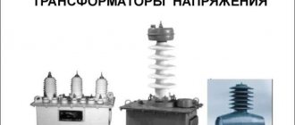
Voltage transformers
Voltage transformers are static electromagnetic devices that change alternating voltage. Such stabilizers are divided into several categories depending on their purpose:
- Power. They are used to increase and decrease voltage, which allows current to be transmitted over long distances and to consumer devices.
- Technological. High-power devices used for technological purposes - furnace, welding and others.
- Low-power. Installed on television and radio equipment, household appliances and various electronic circuits.
- Measuring. Used to expand the measurement boundaries of devices.
Voltage transformers can be used for both monitoring and measuring voltage and power. They can power alarm systems, electrical automation circuits and effectively protect power lines.
Step-down transformers
To connect devices for which the voltage of 220 V is too high, step-down transformers of 15 or 10 volts are installed. The advantages of such transformers for the home are the following characteristics:
- Protection against fire and electric shock, which is important when using such devices in rooms with high levels of humidity - bathrooms, bathhouses and others.
- Minimum electricity consumption - low-voltage lighting devices consume several times less energy, unlike standard ones.
- Increasing the service life of devices.
Chargers for various gadgets and household devices are equipped with integrated transformers, and therefore they do not require the installation of such stabilizers. Self-installation of transformers for the home is necessary when installing low-voltage lighting based on halogen and LED lamps.
Problems in electrical networks
Electricity is supplied to homes through the supplier's power lines and step-up transformers, traveling several hundred kilometers. The loads will be divided between the connected houses after installing the step-down unit. Installing an individual transformer is much more profitable, but it is also more expensive - the internal electrical network will receive a current reduced to 220 V.
The problem of regular voltage drops in the electrical network, during which devices cannot function normally, can be solved by installing a step-up transformer.
Which transformer is called a step-up transformer?
A step-up transformer is an ordinary transformer (see the purpose and principle of operation of a transformer) that increases the voltage value of an electric current. On the primary winding it is lower, and on the secondary winding it is higher. Thus, the voltage at the output of the device is higher and, due to a certain number of turns of the winding and cross-section, has the desired value.
The principle of operation of a step-up transformer is the value of K (transformation ratio).
When K>1 the transformer is a step-down transformer, and when K is a step-up transformer circuit
Application of step-up transformers
The devices are installed in electrical lines and power supplies of consumer points. According to the Joule-Lenz law, as the current increases, heat is released, which heats the wire. To transmit energy over long linear distances, the voltage is increased and the currents are decreased. When reaching the consumer, the power is reduced, since for safety reasons it would be necessary to use massive insulation.
At the beginning of the chain, a step-up transformer is installed, and at the receiving point the indicators are reduced. Such combinations are used repeatedly along power lines, achieving favorable conditions for transporting electricity and creating acceptable values for the consumer.
Due to the presence of three phases in the network, three-phase units are used for energy transformation. Sometimes a group is used in which the devices are combined into a star model, with a common conducting rod.
Although the efficiency of high-power units reaches almost one hundred percent, a lot of heat is still generated. A typical 1 GW power plant transformer produces several megawatts. To reduce this phenomenon, a cooling system has been developed in the form of a tank containing non-flammable liquid or transformer oil and a strong air heat distribution device. Cooling is often water-based; the dry principle is used at low power.
Step-up toroidal transformer
As you understand, when we say “toroidal transformer,” we usually mean a network single-phase transformer, power or measuring, step-up or step-down, whose toroidal core is equipped with two or more windings.
A toroidal transformer works in principle the same way as transformers with other forms of cores: it lowers or increases the voltage, increases or decreases the current - it converts electricity. But a toroidal transformer, with the same transmitted power, is smaller in size and lighter in weight, that is, has better economic indicators.
The main feature of a toroidal transformer is the small total volume of the device, reaching up to half in comparison with other types of magnetic cores.
The laminated core is twice as large in volume as a toroidal strip core with the same overall power.
Therefore, toroidal transformers are more convenient to install and connect, and it is no longer so important whether we are talking about internal or external installation.
Any specialist will say that the toroidal core shape is ideal for a transformer for several reasons:
- firstly, saving materials in production,
- secondly, the windings evenly fill the entire core, distributed over its entire surface, leaving no unused spaces,
- thirdly, since the windings are shorter, the efficiency of toroidal transformers is higher due to the lower resistance of the winding wires.
Winding cooling is another important factor.
The windings are effectively cooled by being arranged in a toroidal shape, hence the current density can be higher.
Losses in the iron are minimal and the magnetizing current is much lower. As a result, the thermal load capacity of the toroidal transformer turns out to be very high.
Energy savings are another plus in favor of a toroidal transformer.
Approximately 30% more energy is saved at full load, and approximately 80% at idle, compared to laminated magnetic cores of other forms. The dissipation index of toroidal transformers is 5 times less than that of armored and rod transformers, so they can be safely used with sensitive electronic equipment.
With a power of a toroidal transformer up to a kilowatt, it is so light and compact that for installation it is enough to use a metal pressure washer and a bolt. All the consumer needs to do is select a suitable transformer based on load current and primary and secondary voltages. When manufacturing a transformer at the factory, the cross-sectional area of the core, the area of the window, the diameters of the winding wires are calculated, and the optimal dimensions of the magnetic circuit are selected, taking into account the permissible induction in it.
Why are voltage-increasing transformers installed near power plants?
Any conductor has its own resistance and therefore heat losses inevitably occur in power lines due to heating of the conductor . The amount of heating is proportional to the square of the current in the circuit, so by increasing the voltage to hundreds of kilovolts, we, according to Ohm’s law, lower the current, and therefore reduce heat losses and the size of power line conductors, saving materials and costs.
- See the principle of operation of transformers in the transmission of electrical energy over a distance
Video: Step-up transformer
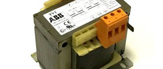
Home Step Up Transformers
They are installed in situations where the voltage of the electrical network is less than the required 220 V. Such models have a constant transformation ratio: with a stable voltage of the electrical network, the final figure will be significantly higher than that required to power electrical appliances, which can cause their breakdown. Output voltage control is provided on some models in manual mode. Industrial transformers cannot be installed at home, as their operation can be dangerous due to the use of specialized cooling oils.
Website for electricians
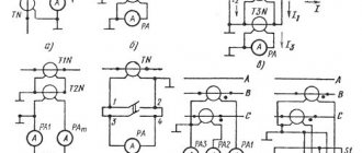
Question 1. What does a transformer consist of? Answer.
The simplest transformer consists of a closed magnetic circuit and two windings in the form of cylindrical coils. One of the windings is connected to a source of alternating sinusoidal current with voltage u1 and is called the primary winding. The load of the transformer is connected to the other winding. This winding is called the secondary winding. Question 2. How is energy transferred from one winding to another? Answer. The transfer of energy from one winding to another is carried out by electromagnetic induction. An alternating sinusoidal current i1 flowing through the primary winding of the transformer excites an alternating magnetic flux Fs in the magnetic circuit, which penetrates the turns of both windings and induces an emf in them with amplitudes proportional to the numbers of turns w1 and w2. When a load is connected to the secondary winding, an alternating sinusoidal current i2 arises in it under the influence of emf e2 and a certain voltage u2 is established. There is no electrical connection between the primary and secondary windings of the transformer and energy is transferred to the secondary winding through a magnetic field excited in the core.
Question 3. What is the secondary winding of the transformer in relation to the load? Answer. In relation to the load, the secondary winding of the transformer is a source of electrical energy with emf e2. Neglecting losses in the transformer windings, we can assume that the supply voltage U1 ≈ E1, and the load voltage U2 ≈ E2.
Question 4. What is the transformation ratio? Answer. Since the EMF of the windings is proportional to the number of turns, the ratio of the supply voltage of the transformer and the load is also determined by the ratio of the number of turns of the windings, i.e. U1/U2 ≈ E1/E2 ≈ w1/w2 = k. The value k is called the transformation ratio.
Question 5. Which transformer is called a step-down transformer? Answer. If the number of turns of the secondary winding is less than the number of turns of the primary winding, w2 1 and the voltage in the load will be less than the voltage at the transformer input. Such a transformer is called a step-down transformer.
Question 6. Which transformer is called a step-up transformer? Answer. If the number of turns of the secondary winding is greater than the number of turns of the primary winding w2 > w1, then k 2 and Si are the cross-section of the core and the total cross-section w1 of the winding turns. Consequently, increasing the supply frequency f makes it possible to proportionally reduce the cross-section of the core at the same transformer power, i.e. square its linear dimensions l.
Question 13. What is the transformer magnetic circuit used for? Answer. The magnetic core of the transformer serves to increase the mutual induction of the windings and, in general, is not a necessary design element. When operating at high frequencies, when losses in a ferromagnet become unacceptably large, and also when it is necessary to obtain linear characteristics, transformers without a core, the so-called, are used. air transformers. However, in the vast majority of cases, the magnetic core is one of the three main elements of the transformer. By design, magnetic cores of transformers are divided into core and armored.
Question 14. What conditions must the design of the transformer windings satisfy? Answer. The design of transformer windings must satisfy the conditions of high electrical and mechanical strength, as well as heat resistance. In addition, their manufacturing technology should be as simple as possible, and losses in the windings should be minimal.
Question 15. What are the transformer windings made of? Answer. The windings are made of copper or aluminum wire. The current density in the copper windings of oil transformers is in the range of 2...4.5 A/mm 2, and in dry transformers 1.2...3.0 A/mm 2. The upper limits apply to larger transformers. In aluminum windings, the current density is 40...45% less. The winding wires can be of a round cross-section with an area of 0.02...10 mm 2 or a rectangular cross-section with an area of 6...60 mm 2. In many cases, winding coils are wound from several parallel conductors. The winding wires are covered with enamel and cotton or silk insulation. Dry-type transformers use wires with heat-resistant fiberglass insulation.
Question 16. How are transformer windings divided according to the method of arrangement on the rods? Answer. According to the method of arrangement on the rods, the windings are divided into concentric and alternating. Concentric windings are made in the form of cylinders, the geometric axes of which coincide with the axis of the rods. The low voltage winding is usually located closer to the rod, because this allows you to reduce the insulating gap between the winding and the rod. In alternating windings, the HV and LV coils are alternately positioned along the height of the rod. This design allows increasing the electromagnetic coupling between the windings, but significantly complicates the insulation and winding manufacturing technology, therefore alternating windings are not used in power transformers.
Question 17. How is the transformer windings insulated? Answer. One of the most important design elements of transformer windings is insulation. There are main and longitudinal insulation. The main thing is the insulation of the winding from the rod, tank and other windings. It is made in the form of insulating gaps, electrical insulating frames and washers. At low powers and low voltages, the main insulation function is performed by a frame made of plastic or electrical cardboard, on which the windings are wound, as well as several layers of varnished cloth or cardboard that insulate one winding from the other. Longitudinal insulation is called insulation between different points of one winding, i.e. between turns, layers and coils. Turn-to-turn insulation is provided by the winding wire's own insulation. For interlayer insulation, several layers of cable paper are used, and the inter-coil insulation is carried out either by insulating gaps, or by a frame or insulating washers. The insulation design becomes more complicated as the voltage of the HV winding increases, and for transformers operating at voltages of 200...500 kV, the cost of insulation reaches 25% of the cost of the transformer.
Literature: Usoltsev Alexander Anatolyevich. Electric cars. Tutorial. 2013
Transformer types
As with any technical device, step-up transformers can be of various types, differing in power ratings, scope of use, etc.
Let's consider each type of this device in more detail:
- The autotransformer has only one winding with a pair of end terminals. As a rule, these are single-phase type transformers, in which there are primary and secondary coils.
- Current transformers have a larger number of windings compared to the previous type. In addition, the design of such devices uses a magnetic core, resistors and optical sensors responsible for adjusting the voltage frequency.
- A power-type unit is a special device that transmits current between circuits through the process of electromagnetic induction.
- The anti-resonance type unit is a cast device that has an almost completely closed structure. Both three-phase and single-phase devices are available for sale. In many ways, these devices are similar to power units, but have more compact dimensions.
- Grounded devices differ from others in the special structure of the windings, which are connected to each other by a zigzag or star.
- Peak transformers are used to separate AC and DC current. These devices have become quite widespread in computer technologies and radio communications.
- Home separation devices are used as a transmitter of electricity from an AC source to the device itself. Household devices with a power of 220 volts are used as a protective measure against the effects of electric current and to prevent interference in the operation of various devices.
During experiments with an electronic transformer, it seems that this circuit is rubber, no matter how much you load it, it doesn’t care. In this article I will show how you can squeeze half a kilowatt of pure power from this simple circuit.
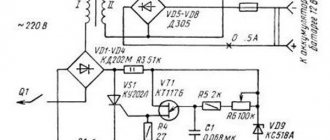
The figure shows a classic circuit of an electronic transformer. This is a half-bridge self-oscillating network switching power supply.
The circuit has two transformers, a power transformer and a feedback transformer.
The power of a circuit depends on several components:
- Input rectifier;
- Power keys;
- Half-bridge capacitances;
- Power pulse transformer.
If you replace them with more powerful ones, you will be able to achieve a higher power output overall.
The active components of our circuit are transistors. These are high-voltage reverse conduction switches. The circuit is launched by a symmetrical dinistor DB3.
The most popular, budget and powerful high-voltage transistors that I know of are MJE13009 and we will use them, but the circuit does not have high efficiency, and one pair of switches may not be enough for our purposes, so a second pair was added to the circuit, as a result the circuit acquired this view:
Powerful resistors in the emitter circuits are equalizing and help to load all transistors evenly.
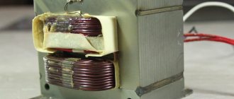
The power transformer is toroidal - wound a long time ago for some project, the core is cool from Epkos, brand N87. The overall power of the transformer is more than 1000 watts.
Since the converter is a self-oscillator type, and the operating frequency strongly depends on some parameters and is extremely unstable, accurately calculating a power transformer is not easy, but an approximate calculation can be done using specialized programs knowing the initial frequency of the converter with a small load, in my case 22 kHz.
In the calculation program, the half-bridge topology is selected and the remaining data is indicated. Here is our mobile application for calculating transformers, created based on the works of Evgeny Moskatov.
I think there is no point in giving the winding data of my transformer, since you will probably have a different core and the winding parameters will be different.
The diode bridge is in the form of a 10-amp diode assembly with a reverse voltage of 1000 Volts, it gets hot, but not much; for long-term operation it is worth installing it on a radiator.
The feedback transformer is a ferrite ring measuring 18x12x7.5mm.
I tore the ring out of the computer power supply, but please be more careful here - such rings are located in the input part of the unit on the 220 volt line, and not at the output, yellow-white, green-blue and other rings that are located at the output of the power supply are made of powdered iron are not suitable for our purposes; we need a ferrite ring. I also used other ferrite rings with permeability from 1500 to 3000 and they worked without any complaints.
The basic windings are identical and contain 3 turns of 0.5 mm wire, the feedback winding is only one incomplete turn of 1.25 mm wire.
Many people have questions with the phasing of the windings of the feedback transformer, if the beginning and end of the windings are mixed up, nothing will work, I have repeatedly told and shown how everything is connected, but questions still arise, so if anyone decides to repeat it, just assemble everything on the board from the archive , and look carefully at these photos.
Naturally, both on the diagram and on the board the dots mark the beginnings of all windings.
Power transistors are installed on a common heat sink, their substrates are insulated, for example, with a mica gasket or more modern heat-conducting insulating material.
Precautionary measures:
- The first start is always done through a 40-60 watt safety lamp;
- Never touch the board during operation;
- Never short-circuit the output of an electronic transformer, it will simply explode, since the circuit has no protection other than the input fuse, but it burns out only after the keys burst.
The voltage at the output of our transformer is variable, I rectified it to an impure constant for more or less adequate measurements, but naturally we will have additional losses in the rectifier.
The STTH6003 rectifier itself, under the housing, contains two powerful 30-amp diodes connected by cathodes, the kind used in welding inverters. The rectifier was attached to the radiator.
We will load it with the good old and damn powerful lamps from a film projector, and something else. Since these lamps in a cold state have a very low filament resistance, and therefore at the initial moment they will consume much more than the rated current from our power supply, I attached a powerful thermistor to the input of the circuit, it will limit the current until the lamps warm up.
The maximum that I managed to get with such a load was 460 watts of pure output power, taking into account the losses in the wattmeter, as well as in the rectifier and on the wires, I think that no one will doubt that the circuit will produce half a kilowatt.
The scheme is very simple, not the most capricious. The load capacity is excellent, but I don’t recommend repeating it especially for beginners, despite the fact that such circuit solutions are used in industrial power supplies for office low-voltage halogen lamps.
PCB here