Sliding gates are modern, easy-to-use designs that are suitable even for small areas. When opened, the sash moves along the fence, without taking up space near the house or at the entrance to it. You can assemble and install such systems yourself, which will save money, for example, on the purchase of automation. For the most practical owners, we have prepared step-by-step instructions for installing sliding gates with your own hands.
Preparing for installation of sliding gates
you need to make a plan.
All this needs to be done more to save time, so that later you just don’t have to run to the store to buy the necessary materials.
Mandatory items of the plan must include:
- data on the terrain for installing the gate (soil freezing depth);
- metal fittings in a complete set;
- necessary tools;
- material for covering the frame.
Particular care must be taken in selecting not only tools, but also components, because the life of the sliding system will directly depend on their quality. Typically, parts are selected to comply with the load parameters so that the gate simply does not sag in the future.
All mechanisms that are included in the design of the sliding system are attached only using electric welding, and here the help of specialists may be required. If you have no experience in operating a welding machine, then it is better not to take on this part of the work.
It is also important to understand that when installing a gate, you need to consider how much space you need to leave, because the gate leaf extends into the inner part of the yard. The canvas should completely go under the wall.
Everything needs to be calculated in advance, because due to the use of electric welding, the gate system becomes non-removable and after its installation it will no longer be possible to fix anything.
It is important to pay attention to the fact that sliding gates can operate from several types of connection, so you need to decide on the best option from the very beginning. There is an option to connect the system to an electric drive, but many modern models also provide connection to an alarm system, which is much simpler and safer
Installation of automation for swing gates: basic rules and nuances
There are many options for the production of gate structures for entry and exit.
Some prefer sliding gates, others prefer swing gates. Today we will talk about the second option. Swing structures can look attractive and noble. Any material can be used as cladding for the structure: wood, steel, corrugated sheets, plastic and sandwich panels.
For greater operating comfort, modern gates are equipped with an automatic mechanism. You can install such a structure yourself, but you need to have knowledge and experience. In such a situation, it is better to entrust the matter to specialists. And we will present our review article as instructions for those who still want to try their hand.
How is automation installed?
First, we select a place to install the electric drive. We will need the mounting base included in the kit. We install the drive on it. Then we install it all on the channel between the carriages. Then we set the gate automation to the operating position to determine the location for installing the drive. You should place the electric drive on the rack with teeth, trace, calculate where you need to direct the drive so that the rack with teeth is located in the middle of the gear and secured to the profile pipe on the outer frame.
The place has been calculated. We put all the other installation equipment on it and weld it around the perimeter. Sometimes the drive needs to be raised for installation a few cm higher. To do this, take a profile pipe and weld the drive to it. We take the required pipe size (40x20, 50x50, 60x30, etc.). After installing the channel on the mounting base, we weld the electric drive to it and secure it with bolts.
Attaching the upper and lower catchers
Catcher
To secure the lower and upper catcher, you need to close the gate all the way. Mark on the post where your gate frame ends. In this place, above and below, you need to secure the mortgages to which the catchers will be attached. Depending on the mortgages, they can be secured by welding or bolting.
The catchers will soften the contact of the gate frame with the support rollers, and also minimize the loosening of the structure in strong winds. The lower catcher also serves to reduce sagging of the frame, which may appear after long-term operation of the gate. Finally, check that your gate is installed correctly. Open and close them several times, make sure they move smoothly and evenly.
Preparation for construction: drawings and diagrams
Installation of automatic gates should begin with drawing up a drawing. Using a pencil, you should draw a diagram of the gate taking into account the dimensions on a sheet of paper. It is advisable to indicate the main dimensions of the parts on the diagram.
The dimensions of the automatic design must be specified as accurately as possible. During the calculation process, the following requirements must be observed:
- when a vehicle enters the garage, a minimum of 30 cm must remain on each side;
- the higher this indicator, the easier it will be to enter the site;
- The width must be determined taking into account the type of vehicle.
For an ordinary passenger car, a width of 2.5 m and a height of 2 m are enough. For a minibus, the height should be about 2.5 m.
The automatic one differs from the standard swing design only in the presence of a drive. At this stage, you should decide on the type of device - whether it will be installed lever or linear. If you plan to install sliding gates, then most often a drive with levers is used. Linear is installed if there is a minimum distance from the extreme part of the support to the loop. If there is a gap of more than 15 cm, then it is advisable to use a lever device.
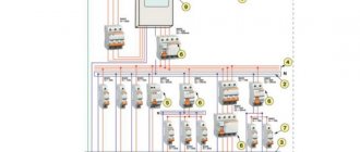
Automation installation diagram indicating the number of cable cores and their cross-sections
Sliding gates will be affected by wind loads, so it is important to take care of protecting the devices in advance. If you plan to install automatic garage doors, then the ceiling level must be lowered by 25 cm
This should be taken into account, since installation will require space under the ceiling structure
If you plan to install automatic garage doors, then the ceiling level must be lowered by 25 cm. This should be taken into account, since installation will require space under the ceiling structure.
The design of the automatic recoil design is practically no different.
Layout of elements of automatic sliding gates
In this case, only one electric motor will be needed.
Installation of limit switches
They need to be bolted to the end rail. Switches can be mechanical or magnetic. Magnetic ones work even during harsh weather conditions. A magnet is mounted on the rack and when it passes a certain point in the gate, it stops. In this case, the switches need to be divided into left and right - one with a plus sign, and the second with a minus sign.
It is best to configure and install magnetic switches at a distance (minimum 1 m). Installing mechanical limit switches for sliding gates is actually very simple. They work using an elementary spring.
Installation of roller trolleys to the channel
Installation of roller carts
Roller carts can be called the most important mechanism, since they must withstand the load of the entire structure, so they should be attached to the channel as securely as possible. The plates for fastening the rollers must be welded to the channel. Everything is done as evenly as possible and in the same plane so that the gate moves freely. To align them exactly, you can use a laser pointer or a stretched cord. Another option is to draw a parallel line on the foundation, which will be a tangent line to the edge of the plate. The plates should be welded in the middle of the channel. To do this, step back 15 cm from the edge, closer to the opening and fix the first plate. The second plate is attached 10 cm from the opposite edge.
Installed roller support
Now you need to fix the roller carts to the plate. They are usually connected using bolts and nuts. You need to tighten them securely and install the gate. Check the smooth running, take control measurements and adjust the position of the roller supports to align the gate perfectly level. To do this, you can use a cord, which must be pulled along the gate opening line, at a distance of 20 cm from the surface and 3 cm from the second post. The cord will serve as a guide to help you align the gate perfectly straight.
Gate foundation
It’s quite easy to determine the size of the foundation, since it has a length equal to 1/2 the width of the opening, according to the formula:
B/2=L
- B – opening width;
- L – foundation length;
If everything is simple with the length of the foundation, then with installation we have many options.
The foundation can be made of the following materials:
- Monolithic U-shaped.
- Solid monolithic.
- From screw piles.
The installation of a monolithic foundation also has small features; you can use reinforcement welded to the channel, anchor bolts or long threaded rods.
Let's consider the option with a channel (power frame), it can be with one or two support posts or without them, in both cases the power frame is attached flush to the existing fence posts. The height of the support pillars corresponds to the height of the gate itself + the height of the roller supports. Using two support posts near the load frame is advisable for wide gates that sway strongly in the wind. If support pillars are not provided, then instead of them, metal mortgages are made into the stone fence.
In the photo, laying the foundation.
Scheme without metal racks.
Photo of the power frame
In order to level the power frame on the opposite side, where the support post with the end roller catcher is located, step back 10 cm (the thickness of the post) from the fence and pull the cord to the last corner of the channel; along its entire length, the edge of the channel should follow the line of the cord.
Installing the top clamp
Upper clamp
To prevent the gate from moving when the gate moves, a latch or guide is installed on top of the post. It will stop the gate and prevent it from swinging in strong winds. To do this, holes for fastenings should be marked on the support post. Make sure to measure everything correctly so that the top frame can fit into the clamp without obstruction.
A bracket must be installed on the pole to secure the guide. If you will be fixing it in concrete or brick, use anchors with a pin diameter of 10 mm. If you are attaching it to metal, then special screws will do. If welding is used, the rollers must be removed.
After securing the fastener, check it. The gate should move smoothly, remain vertical, and the rollers should fit tightly around it.
Gate elements and components
Elements and components
Basically, with everything you need to get the job done, you should have no problem installing your gate. You don’t need particularly deep knowledge in construction, just basic knowledge, materials and following the recommendations of experts.
For the work you will need consumables, but the main and important part of the elements is the fittings responsible for the movement of the gate. It consists of:
- roller trolley or carriage (2 pcs.);
- lower and upper catcher;
- U-shaped beam guide;
- gear rack;
- removable end roller;
- top lock with rollers;
- plates for fixing the roller trolley.
Pay attention to quality
When choosing high-quality accessories, pay attention to trusted manufacturers, taking into account the price and quality of the products. You can also seek help from professionals who will help you choose the best option.
It is much easier to buy a ready-made gate kit with all the necessary elements, which you only need to assemble and install in place. It contains special installation instructions, thanks to which you can easily do all the necessary work.
Design
Different brands and models of electric drives may differ from each other, but the main components and operating principle are almost the same for all.
- Electric motor. A power unit that is used to convert electrical energy into mechanical energy.
- Gearbox. This equipment allows you to reduce the rotation speed and transmission of the electric motor.
- Rack. Together with the gearbox, it forms a gear train. Through the gearbox, movement is transmitted from the engine to the gear, and then to the rack itself. And since it is fixed on the guide beam with the gate leaf, when it moves, the leaf also moves to the side. Usually it is not included in the automation kit and is purchased separately.
- Control block. Allows you to start the engine manually by pressing a button.
- Receiver. It receives a signal from the remote control and then gives a command to turn on the electric drive.
On a note! The remote control is not always included in the purchased automation kit; sometimes it has to be purchased separately. It is necessary to immediately clarify this issue when purchasing.
Preparing the embedded element
Mortgage
In order to make an embedded element, you will need:
- channel 18–20 cm wide (it can be replaced with a corner of the same dimensions);
- reinforcement Ø 12–15 mm;
- welding machine.
Installation of embed
The filling element is a structure made of channel and reinforcement, which in the future will be installed in the trench and will be concreted. Take a metal channel and cut it to the length of the entire trench. If it is 2 m, then the channel should be 2 m long. After that, reinforcement must be welded to it to form a metal frame. The length of the reinforcement bars must be 5–10 cm greater than the depth of the trench so that it can be sunk into the ground. How exactly you will weld the reinforcement depends on you, there are no restrictions here, it can be welded in increments of 15 cm. The main thing is that the frame is strong and has a vertical base that is connected by jumpers.
Once the frame is ready, it can be installed in the trench. But before this, the bottom of the trench should be filled with sand or small crushed stone and compacted, making a cushion for the foundation 5 cm high. Sink the reinforcement so that the surface of the channel is flush with the road surface. Using a building level, align the frame perfectly level. If there is a strong distortion on any side, remove the frame and add sand to that place. If the mortgage is not level, it will prevent the gate from moving correctly.
Level with the road
Main components of automatic gates
Main elements of automatic gates
Gates equipped with an automatic mechanism open quickly, eliminating unnecessary user actions. The design includes:
- rigid metal frame;
- electric drive;
- support pillars, or racks;
- metal valve;
- decorative cladding;
- big loops.
To further strengthen the frame and increase its wind resistance, stiffening ribs are installed inside.
Pouring the foundation
Formwork is installed and poured
Once you have laid the wiring, the embedded element can be filled with concrete mixture. For this you will need M400 cement, sand and crushed stone. The proportions are as follows: for 1 kg of cement you need 3 kg of sand and 4–5 kg of crushed stone. Water should make up half the weight of all ingredients. It turns out:
1+3+4=8
8/2=4
The total is 4 liters of water per 1 kg of cement, 3 kg of sand and 4 kg of crushed stone. Mix the required amount of solution and fill the trench
It is important that the surface of the channel is not completely concreted; the concrete must be at its level. Now the foundation needs to be left to dry
This will take 3–5 days, during which it will get stronger and be reliable enough for further work.
Automation installation sequence
If you purchased not only a gate drive (the motor itself with a gearbox and gear assembly), but also a set of additional automation (photo sensors, signal lamp, additional antenna), then the automation is installed first and only then the drive - since all the wires are from auxiliary devices are brought out from the bottom up - from underground through the drive under the drive and then to the drive terminal blocks.
- First of all, we fix the rack at the bottom of the door leaf. At this stage, the height of its attachment is not very important. Do not worry that the drive gear may not engage the rack, since you can subsequently adjust the height of the drive itself (along with the gear) above its base using four adjusting screws.
- To attach the photocells, we need to lay a two-core wire between the internal posts of the sliding gate. If there are none, then I recommend digging in low additional posts on the side of the yard and attaching photocells to them. Can it be mounted on external poles? It is possible, but it is better to do it from the side of the courtyard for anti-vandal reasons. In our case, we already had internal pillars and we needed to install photo sensors on them and connect them with hidden wiring, for this it is necessary: at a height of 50 cm from the ground, drill holes in both pillars directed inside the gate opening; dig a trench connecting both poles and lay a two-core wire in it in a case made of technical polyethylene pipe; gain access to the inside of the pipe from its lower end - for hidden wiring entry.
- We ran the wire underground, brought its ends up, first inside the pillars, then brought them out through the drilled holes. Now we begin the installation of photo sensors. In this case, the photocells must first be fixed to the pole and only then can they be switched. Do not cut off the excess wire at the root! It is better to subsequently tuck the excess inside the pillar.
- We install a signal lamp and a remote additional antenna (if available). To do this, take the wires according to the table “ Typology of cables and their minimum cross-sections
", published above. As a rule, this is a coaxial cable with a characteristic impedance of 50 Ohms for the antenna and a two-core wire with a cross-section of 2x1.0 mm for the signal lamp. The length of the wires is chosen so that it is enough to pass them from top to bottom inside the pole located closest to the others to the installation site of the drive itself. Remembering about vandals, we again recommend installing the signal lamp and antenna on an internal pole (if there is one), and not on an external one. If there is only one pole, mount it on it or weld a platform to it. To mount a signal lamp on the top end of a post, the post must be welded on top with a steel plate (rather than plugged with a plastic plug). The base of the lamp is installed on a flat surface and secured to it using self-tapping screws. Accordingly, it cannot be secured to the unwelded end of a hollow pipe. Many people simply weld a platform to the pipe (post).
- The heart of the entire system is the gate drive, so switching of all auxiliary devices is carried out on terminal groups installed on the drive. In this regard, we now need to connect all the wiring to the drive. All wiring going to the drive is connected to it in a hidden way - from below. To do this, there are holes in the base of the drive, and in the drive itself there is a small cable channel in order to pass all the wires through the drive, from bottom to top, to the terminal groups. Taking into account the above, we need to make a corresponding hole in the steel embed (cut using an angle grinder). Then, using a hammer drill, punch a channel passing through the hole in the embed down and to the side - into the trench for the drive.
- We weld the base of the gate drive to the mortgage using electric welding, and then adjust the height of the drive motor above its base using four adjusting screws. It is necessary to ensure that the drive gear engages with the rack (but there should be a small gap between the gear and rack!).
Installation of automatic gate security elements
The signal lamp creates a light signal when the blade moves. She warns those who remain in the opening about the danger. Photocells prevent the doors from closing if there is a car, person or animal in the opening.
The wiring for all these mechanisms is laid at the stage of laying the supports. Then all cables and twists will be securely hidden. If all this is not done in advance, then you will have to drill holes in the pillars. The wires will then be laid through the entrance. But the paving slabs or asphalt still have to be dismantled. This will cost additional money and time.
The optimal solution for everyone is to entrust the work to professionals. They will do the job efficiently, reliably and cause minimal damage to the surrounding area. After installation, be sure to check how the photocells work. Launch the gate and stand in the opening. The gate flaps should suddenly stop moving and close.
Types of automatic country or garage gates
There are the following types of automatic gates:
- recoil;
- swing
The design of automatic sliding gates, which are a single piece, has a mechanism that opens the doors to the left or to the right. It does not provide the necessary tightness to the premises, since the gate must move using rollers on a special rail. It is advisable to install automatic open gates at the entrance to the territory.
The automatic swing gate system involves the installation of double doors, as well as the connection of automation that drives the mechanism. The structure is controlled using an electric drive. An assessment of a number of initial parameters allows you to choose it correctly:
- valve size;
- weight of the entire product;
- length from the middle of the door hinges to the side walls.
The doors can open outwards or inwards. The first method is the most suitable. Hinged models have the following disadvantage: the possibility of breakdowns due to the presence of any obstacle in the way when the doors close.
The cost of swing structures is the main argument that is the reason for the increased demand for this product. For example, a gate whose dimensions are 2x4 m costs the buyer 0.8–1 thousand. e. If there is a gate in the door leaf, the cost of the model increases by 25–30%.
A necessary condition for installing fast gates of any type is the availability of free space, which allows you to open the doors without interference. To make the frame for such models, a profile with high rigidity is used. It should be paneled with metal or wood.
Automatic forged gates always look presentable. The design features durable, elegant doors that can cover openings of different sizes. In this case, a separate gate is not required. The disadvantages of this model are:
- the need for free space;
- high cost of the product.
Models of forged carved grilles are always very beautiful and elegant.
This is interesting: Electrical project in a private house (video)
Do-it-yourself automation installation
Automatic swing gates, if installed by the owners themselves, will be less expensive financially. It is a rather complex procedure, which even professionals in this matter are not always able to perform. During installation, strict adherence to a large number of criteria is required; making mistakes is unacceptable: incorrect functioning of the system during operation can lead to its breakdown. Installing automation on swing gates, if you do it yourself, requires knowledge of the key postulates about the turning mechanism (its parts, installation rules), which will prevent mistakes and have a positive effect on the result.
Required materials and tools
Do-it-yourself installation of swing gates with an automatic mechanism is done using certain materials and tools that must be prepared in advance. Compliance with all rules guarantees the normal operation of systems and prevents errors and breakdowns.
The list of all components of swing gates consists of:
- metal rigid frame;
- cladding (the use of forged gratings is allowed);
- racks for supports;
- garage hinges;
- metal valve;
- electric drive.
Gates with proper installation of automation (swing) will require the following materials:
- profile pipes, cross-section – 40.0×30.0 mm or 60.0×30.0 mm;
- the material from which the casing will be made (corrugated sheeting, plastic panels or wood);
- profile pipes or channel (quality is equivalent);
- bricks;
- primer and cement mortar (from sand, cement, crushed stone);
- solvent;
- electrode;
- self-tapping screws for metal or rivets;
- three-core cable;
- insulated polyvinyl chloride pipes.
The list of necessary tools consists of:
- shovels;
- Bulgarians;
- molar brush;
- automatic circuit breaker (residual current device);
- indicator screwdriver;
- metal brushes;
- building level;
- measuring instruments;
- welding machine;
- screwdriver.
Selection of electric drive
The electric drive distinguishes gates that are opened manually from those that are opened and closed not automatically, but with the application of mechanical forces. Its essence is as follows: the lever is controlled by the engine thanks to the existing gearbox. In addition, the kit includes photocells, a control unit, a lock (it unlocks the keys), and a warning lamp.
There is a classification of electric drives into typical categories based on several parameters.
- Mounting location:
- on the ground;
- underground.
- The principle on which the work is based:
- hydraulic;
- electromechanical.
- Methods of effort:
- lever automation;
- linear mechanisms.
Linear electric drive. Linear electromechanical automation is one of the most popular. This type of rotary mechanism is distinguished by: affordable cost, ease of installation, external opening. The essence of this type of device is as follows.
- The engine rotates the propeller using a gearbox.
- The nut moves with a screw in the same direction as the guide.
- The rotational energy is transformed: the movement becomes linear.
- The moving nut helps to open the structure.
With the help of the control unit, the engine slows down at the end of the cycles (before the switch responds) to ensure long-term operation of the drive.
Lever type of automation. This ensures smooth and reliable operation of the gate. The work is based on the following principle.
- The motor energy is transferred to the vertical shaft using a gearbox.
- The crank is held using the pants (levers).
- They move the gates.
Electric drives are distinguished by control of engine speed due to the presence of sensors and limit switches.
Underground installation of lever-type electric drives is possible. This is done in rare cases due to the high probability of water ingress and possible freezing during the cold season.
Hydraulic type of automation. The essence of the work is based on the following points.
- With the help of the engine's reversible hydraulic pump, the flow of working solution to the hydraulic cylinders is enhanced.
- By means of hydraulic cylinders, the door leaves move (opening, closing).
- System security is ensured by sensors.
Hydraulic electric drives are no less reliable than linear electromechanical drives.
Installation of a linear type of automation for swing gates can be done in three ways, depending on the direction in which the gate systems open:
- to the outside;
- to the inside;
- to the inside, including making a recess.
Installation of automation when opening the gate outwards
When preparing the opening, it is necessary to make mortgages. To do this, a metal pipe with a cross-section of 10.0×10.0 cm (a channel can be used) is laid in the center of the brick pillar. Next, the fittings are welded. For a profile pipe (section 6.0×3.0 cm), embeds are produced. Their output location is a support pillar. Hinges are welded to it. Number of mortgages – 3. The height of the drive mounting must coincide with the location of the mortgages.
As the structure is being assembled, automation is installed: the first bracket is welded to the frame frame, the second to the post embedded. In this case, it is necessary to comply with all standards.
The laid wires must be checked: intact, well insulated.
Installation of automation when opening the gate inward
The length of the gap between the center of the loop and the border of the supporting column is six centimeters. When the door leaf swings to the inside, the arrangement of the pillars is identical to the outer direction of opening. It is advisable to lay it in the center of a channel or metal pipe. Then the mortgages on which the brackets are attached are removed.
Stops must be installed at the extreme angles of the gate travel. The material of the stops is reinforcement or angle.
Installation of automation when opening the gate inward: making a recess
The electric drive can be installed after the installation of swing gates. This option is suitable for linear actuators. If the pillar is brick, a niche is made in the center. Installation is carried out in compliance with all conditions for installation inside without recess.
Installation of electric gearboxes
When choosing automation, certain factors should be taken into account:
- The automatic system must be selected in accordance with the area, weight and windage of the gate.
- Vertically aligned sashes (for easy and correct operation).
- The side in which the portal opens (outward or inward).
It is best to install an automatic electric drive in the middle of the sashes, but if necessary, it can be installed from below and from above. The main condition is to attach the second bracket to the frame of the structure. If the engine is not installed correctly, there may be distortions during its operation, which will lead to jamming during operation.
The doors open inwards
This option is more complicated, since when opening the shutter this way, the installation requirements limit certain dimensions. For example, the distance between the drive and the center of the loop should not be more than 50-60 mm. Difficulties may arise if the pillars are made of stone or brick; in such cases, the loop is located in the middle of the support. In such cases, the distance from the center of the hinge to the edge of the post is 15-20 cm, and it is impossible to install an electric drive on such a sash.
In most cases, for a portal that opens inwards, the loop is placed closer to the yard, and if the post is made of metal 100*100mm (the loop is in the middle, but the required distance to the edge of the post is 50 mm). In such cases, a special steel bracket for the electric drive is welded to the mortgage or to a metal support.
Installation of automation
The doors open outwards
For this type of gate, there are no difficulties when installing linear drives. When installing, it should be taken into account that linear-type gearboxes will reduce the opening of a swing structure by 15 cm on each side, and it is better to install them high so as not to be touched by vehicles when moving.
The bracket should be extended by 5 cm using an additional plate and attached to the mortgage using a welding machine. The bracket inserts can be welded to the pipe or to prepared anchors.
Automation of the gate movement control process
If swing gates with automation are planned, their construction must be carried out taking into account the installation of an electric drive according to the accompanying diagram.
The selection of automatic elements should be done taking into account:
- weight, width, windage of the doors when exposed to wind;
- the direction in which the gate parts will open;
- The door panels must be positioned horizontally or vertically, strictly observing the direction and adjusting the ease of movement.
The control unit box is secured when the wires and communications are disconnected.
Receiver installation, remote control programming
The receiver, through which control signals pass, is installed in a special connector. Its location is the control board. You still need to place two jumpers in this connector. They are used to test the drive:
- “2-1” if there is no need to press the “Stop” key;
- “2-C1”, if there is no need for photocells.
The photocells are connected last, so an appropriate jumper is required. When the receiver is connected, it’s time to move on to programming the remote control with which the remote control occurs. This is done in full compliance with the manufacturer's instructions.
Connecting photocells and signal lamp
Photocells are installed on special posts (it is possible to use the places provided for them), then they are connected to the board in accordance with the diagram. For the remote lamp, the actions are similar.
The installation height of photocells ranges from 50.0-70.0 cm. They are designed to prevent damage to the car when it stops at the gate (prevent impact).
Programming automatic gate closing
Automatic closing sequence: After a twenty-second pause in the open position, the gate closes without the need for additional commands. If owners want to close by pressing a button, reprogramming is possible, but only according to instructions, or it is possible to switch to the appropriate mode by pressing a key.
Installation of safety photocells
Their installation is easy. Photocells are 2 devices - one of them sends a beam of light, and the second receives it. The sliding gate will move normally as long as there is a light signal. When a shutter appears for the beam (person, machine, animal), the gate stops closing.
Installation of photocells for gates can be done in different ways.
All that is required is to secure them against each other to expose the light signal and connect. You can make special columns or pedestals and weld them to them. Another simple way is to make columns from the remains of a profile pipe and install photocells. As you can see, there are many options, and your task is to choose the best option.
To connect the wires, we make holes in the pipe and run them under the roadway. To avoid breaks, we hide the wire in a corrugated hose. Photocells can be secured using ordinary self-tapping screws.
Electrical supply and door frame installation
carry out electrical wiring
This, of course, significantly increases the cost of not only the work, but also the gate structure itself. Install the wiring immediately after finishing work on the foundation. The cable is laid in the foundation structure, and a special corrugation is used to lay it.
It is important to calculate the place where the cable bundle will ultimately exit in advance, so that you can then stretch the entire cable into the room for connection to the electrical network. Next, when installing the gate with your own hands, you can begin assembling the necessary sliding gate consoles
This may require profile pipes. Dimensions can be selected independently in accordance with the scale of the design
Then, when installing the gate with your own hands, you can begin assembling the necessary sliding gate consoles. This may require profile pipes. The dimensions can be selected independently in accordance with the scale of the structure.
Profile pipes are cut, if necessary, to the required length and prepared for welding work. Experts usually recommend welding pipes so that the horizontal posts end up on top of the vertical ones.
This method has already shown in practice that the structure turns out to be stronger. In addition, when installing horizontal racks on top, the process of corrosion on the frame is prevented. But in this case it will be necessary to make protection for the horizontal cross-sections.
To do this, after assembling the structure, you need to clean all joints and paint the frame with a special paint that prevents the spread of rust. The crossbars must be welded every 50 cm if the gate has a width greater than 1.5 meters. This will prevent the fabric from sagging in the future.
Installation of roller base and blade
The roller base is considered one of the most important mechanisms in a sliding gate system. The thing is that this part bears the entire load from the canvas. That is why all fastenings must be reliable.
Most often, for this purpose, fasteners are welded to the channel. Immediately after the installation of the rollers, the gates are installed on them, and after that, replacements are carried out, which make it possible to check the stability and level.
In order for the gates to operate smoothly and without hitches on the roller system, they are installed on the same plane, but accuracy can only be checked using laser pointers.
DIY sliding gates: step-by-step guide and diagrams
Published: February 02, 2018
Do-it-yourself sliding gates: where should you start, how to choose components, what order of actions to follow, what should you pay attention to first? This article will be useful to all those who are interested in the question of how to make sliding gates with their own hands, and also contains drawing diagrams and instructions for installation work. Below is a diagram of sliding gates, a diagram of the foundation of sliding gates, recommendations for preparing the opening, and installation recommendations.
Sliding gates are a very popular and most convenient type of gate. The name is due to the design features - they roll away from the sides and move along the fence. Over the past ten years, sliding gates have become incredibly popular. This popularity was facilitated by the development of a new, improved design - the gates became more affordable in price, got rid of the top guide and no longer require maintenance.
This article describes the most logical and optimal procedure for producing and installing sliding gates with your own hands; in addition, it contains drawing structures for a welder.
In order to independently make a sliding gate frame and install it, in addition to one desire, you must have a welding machine (inverter), as well as have welding skills. In addition, you will need a tool for cleaning seams and cutting metal. You will need a site with a relatively flat surface in order to organize some kind of slipway for assembling the gate leaf.
We will divide the work into five parts: measuring, working with the foundation, manufacturing the frame, installing the structure and finishing the canvas, installing the drive and related devices. Before starting work, it is necessary to clearly understand how exactly sliding gates work.
Let's look at a diagram of a sliding gate, on which all the main components are drawn:
The door leaf is made of profile pipes and is approximately 1.5 times wider in length than the opening. It can be conditionally divided into two structural parts: the main one, which obscures the opening and is subsequently subject to finishing (for example, corrugated sheets, wood) and the cantilever part, the need for which is determined by the design features. A guide 3 is welded to the lower edge of the door frame, with the slot downwards. Thanks to it, the sliding gate moves along the roller carriages 5, which are located inside. Conscientious craftsmen and prudent owners always use adjusting stands 4 to attach carriages. They make it possible to adjust the structure in two planes. Covering the opening, the sliding gates are hinged by the end roller 2 onto the lower trap 1. They are held by the upper corner by the upper roller trap 8, relieving the wind load. For this, you also need a bracket with rollers to prevent lateral rolling 7. The guide is protected from snow and fallen leaves by a special plug 6
Stage one. Do-it-yourself measurement and design of sliding (sliding) gates
To correctly calculate the length of the structure, you need to measure the initial data. The gate leaf can be made for the existing opening or can be designed simultaneously with the fence. Let's assume that the fence is already installed and we have an opening that needs to be closed. The opening is limited by pillars.
To design a gate you need the following dimensions:
- opening width
- estimated height of the installed structure - from the level of the finished road surface
- the direction of rollback of the canvas and the length of the rollback space.
The canvas can roll to the left or right of the opening. The direction of movement is determined when viewed from the yard. To roll back, you need free space along the fence = width x1.5. As a rule, the height of the gate is approximately 10-15 cm lower than the fence. The post of the opening, behind which the gate leaf rolls back, must be at least 5 cm higher than the gate to install a bracket against lateral swings 7. The gate leaf, when moving away, “hides” behind the fence. The total height of the gate is the height of the door leaf with the guide + the height of the gap under the gate.
The height of the clearance depends on the level of the mounting plate (channel) and on the height of the roller supports that are used in the structure. If the mounting plate is installed at the same level with the road surface, and the sliding gates are assembled on the ROLTEK Micro, ROLTEK ECO or DACHA system, then the clearance will be from 8 to 10 centimeters. For winters in central Russia, this gap is optimal.
If you are just designing a future fence, below are some tips that will help you save money and simplify subsequent installation.
With an opening width of up to 5 meters, you can significantly save on components, since they are divided not only by the possible weight of the structure, but also by the width of the possible opening to be closed.
A gate built into the door leaf has many disadvantages: it reduces the rigidity of the structure, cannot be equipped with an electromechanical lock, has a high (about 20 cm) threshold and is dangerous. If there is such a possibility, it would be wiser to make the gate stand-alone. It is much safer and more convenient to use.
For an opening limited by pillars of stone or brick, it is necessary to provide in advance embedded parts for installing upper and lower traps, and a roller bracket from wind loads. The embed is a metal plate with reinforcement welded perpendicularly. The reinforcement holds the embedded part in the concrete.
Stage two. Making the base - foundation
There are several options for preparing the base for sliding gates with your own hands.
Traditional and most expensive
To the side to roll back the gate, parallel to the fence on the side of the yard, you need to dig a trench. Its length is 1/2 the width of the opening (for example, with an opening of 4 meters, the length of the pit = 2 meters), the width of the trench is approximately 50 cm (if you can make it narrower, this will not affect the quality, and you will save concrete), and the depth = 1 ,7m. To avoid “sliding gate distortion,” the depth of the trench is made lower than the soil freezing level.
A mounting plate is placed in the hole parallel to the fence. It is made from a channel 12-16 mm wide and half the width of the opening. The reinforcement grid will hold the channel in the concrete; it is knitted from reinforcement with a diameter of 12-16 mm. In order to save money, you can replace the fittings with unnecessary scraps of metal (angle, square or professional pipe)
The mounting plate, with the reinforcement facing down, is placed in the pit. The conventional “zero” for the gate design is the upper plane of the mounting plate. Its position determines what the minimum gap under the gate leaf will be. We recommend laying the mounting plate at the same level as the road surface - then you will get a minimum gap of 8 cm. The mounting plate should be laid as close as possible to the fence post.
Particular attention should be paid to the parallelism of the longitudinal axis of the slab channel and the opening line. The path of movement of the gate will run along the center of the channel. The channel must be laid strictly horizontally.
Pillar foundation
The support-column foundation for the gate consists of two reinforced concrete pillars, the body of which is located in the ground. The pillars are connected to each other by a mounting plate, which serves as a base for the roller trolleys. Using a garden drill, two holes are made with a depth of 1.7 -2 m and a diameter of 20 to 35 cm. The distance between the piles should be 20-30 cm less than the width of the opening. Holes for the piles must be drilled close to the fence. The pits are reinforced and embedded in them (a metal plate with reinforcement welded down). The structure is concreted. The level of the upper platform of the mortgage must coincide with the level of the road surface. When the concrete gains initial strength, you can weld the mounting plate and begin installing the canvas. The axis of the mounting plate should follow the path of movement of the future gate leaf. The plane of the slab must be positioned horizontally.
Foundation on screw piles
The practice of installing gates on screw piles in Russia is new and there have been no reviews of long-term use of gates installed this way. Customers who have had gates installed on stilts speak positively about them.
The big advantage of such a foundation is its low price and the ability to complete the work in one day, but to screw in a pile you either need to put in serious effort and skill, or use expensive equipment.
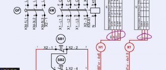
Preparing electrical wiring for installation of automation
For gates that will be opened automatically in the future, electrical wiring must be laid at the stage of laying the foundation.
Laying wiring in the ground and foundation must be done in steel or HDPE pipes. The pipes used must be intact in length. Before laying the pipe, you need to pass the wire inside it, so that later you can easily pull the wires through. The diameter of the pipe inside must be at least 30 mm. The geometry of the pipes, seams and bends should not interfere with the free passage of wiring. The depth of pipe laying depends on the soil at the installation site. The recommended type of cable for wiring is PVS flexible copper cable.
You can lay the cable in HDPE pipes with an internal diameter of 15 - 25 mm. In this case, the cable should be laid in the HDPE pipe in advance. To avoid water ingress, the electrical wire outlets must be securely sealed. An armored cable can be used.
Electrical wiring installation
General rules for laying cables
When installing wires yourself, it is recommended to take into account certain rules:
- You should leave 1-1.5 free ends of the wiring.
- The control unit is installed on the side where it is easier to connect the 220 V power cable.
- The wiring starts with corrugation only from the bottom side.
- It is recommended to leave free ends of 1-1.5 m. The control unit has a box to prevent water from entering.
- Each drive requires a three-wire cable to power the electric motors.
- The power cable should be positioned slightly lower than the mounting height of the drive.
Electrical wiring
Important! To avoid breakdown of the automation due to voltage surges, it is recommended to install a voltage stabilizer.
Conditions for connecting photocell cables
There are also certain rules for wiring photocell cables:
- Two-core wires 4*0.22 should be used for connection.
- If the gate is made of opaque material, it is necessary to install a second pair of photocells behind the gate (the kit includes only two photocells, so you need to purchase another pair).
- They should be mounted at a height of 500-600 mm from the ground surface.
Automation for sliding gates - power supply
Let's return to our gate drive and automation kit. How many and what kind of wires do we need to lay to our gates in advance when laying cables along the site? We will answer this question below, but first things first. In order not to waste time on empty discussions on the topic “which gate drive is better to choose,” we will simply say that there is a CAME
, there is nothing more! The drive for sliding gates (like everything else) is also selected based on the weight of the gate leaf. The heavier the sash, the more powerful the drive is needed.
Automation kits for CAME sliding gates are described below
:
| Set CAME ВХ-243 | Set CAME ВХ-68 | Set CAME ВХ-78 | Set CAME BK-1200 | Set CAME BK-1800 |
| Sliding gate weight up to 300 kg, high work intensity (70%). | Sliding gate weight up to 800 kg, work intensity 30%. | The weight of sliding gates is up to 800 kg, the operating intensity is 30%, the function of incomplete opening of the gate (“wicket”). | Sliding gate weight up to 1200 kg, average work intensity (50%). | Sliding gate weight up to 1800 kg, average work intensity (50%). |
| Current consumption=7.0 A; Power=170 W | Current consumption=2.6 A; Power=200 W | Current consumption=2.4 A; Power=300 W | Current consumption=3.3 A; Power=380 W | Current consumption=4.2 A; Power=480 W |
| EACH SET CONTAINS : gearbox-drive (1 pc.), radio receiver AF43RU (1 pc.), TWIN2 remote control (2 pcs.) | ||||
| IN ADDITION, any set can be completed with : antenna TOP-A433N (1 piece), photocells DIR 10 (set of 2 pieces), signal lamp KLED 24B (1 piece). |
| Connection | Cable length 1 | Cable length 10 | Cable length 20 |
| Supply voltage 230 V | 3x1.5mm 2 | 3x2.5mm 2 | 3x4.0mm 2 |
| Signal lamp | 2x0.5mm 2 | 2x1.0mm 2 | 2x1.5mm 2 |
| Photocells-transmitters | 2x0.5mm 2 | 2x0.5mm 2 | 2x0.5mm 2 |
| Photocells-receivers | 4x0.5mm 2 | 4x0.5mm 2 | 4x0.5mm 2 |
| Power supply for additional devices | 2x0.5mm 2 | 2x0.5mm 2 | 2x1.0mm 2 |
| Control and safety devices | 2x0.5mm 2 | 2x0.5mm 2 | 2x0.5mm 2 |
| Antenna connection | Coaxial cable RG58 or equivalent with a characteristic impedance of 50 Ohms |
In fact, all that needs to be done in advance is to connect the supply voltage to the gate drive (first line in the table above). Use a wire with a cross section of 3 x 1.5mm 2 or 3 x 2.5mm 2 . This must be done through a separate machine, which must be de-energized until the installation of the gate drive and automation kit is completed. This supply wire must be brought out near the mortgage on which the gate drive will be installed.
In addition to this, the only wire (going to the sliding gate from the panel), in principle, nothing else is needed, but if you want to be able to open and close the gate not only using remote controls, but also, for example, using buttons from the house, lay additionally twisted pair. If you plan to install an additional intercom (for communication from home with visitors at the gate and opening/closing gates, gates, etc.) - lay a twisted pair cable, a two-core power cable 2x0.5mm 2 or 2x0.75mm 2 from the house to the gate. If you plan to install an analog video camera (as part of the intercom or separately), lay an additional coaxial television cable with a characteristic impedance of 75 Ohms.
We remind you that the basic package of the drive does not include photocells, a signal lamp, or an additional antenna; therefore, if you did not purchase them separately, you will not need any additional switching except connecting the drive power cable. On the other hand, if you decide to purchase and connect them later, you can easily do so at any time. In this case, the maximum difficulty that you may encounter is the need to dig a small trench to lay the wire connecting the photocells on two poles on opposite sides of the gate opening.
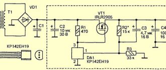
Characteristics of valid nodes
ACSTM 114R - wireless two-channel remote control kit
When installing automation suitable for sliding gates and doing all the work yourself, you need to take into account the technological aspects of the product.
Control type
The standard control unit can be replaced with the ACSTM 114R. A two-channel wireless module opens and closes the doors according to the “code jump” principle. The machine's alarm panel can be used as a control mechanism. It will prevent overloading of the structure and eliminate the risk of foreign objects getting between the sashes.
Basis for the mechanical drive part
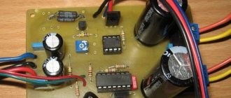
The manufacture of an electric drive for sliding gate leaves is carried out manually on the basis of a DC gearbox/motor powered by 12-24 V. Such a circuit operates uninterruptedly in bad weather and in case of blockages. Suitable electric motors:
- windshield wiper of the VAZ-2110 car with high output torque;
- MAZ windshield wiper - an element from a truck is designed for 24 V and operates at high power;
- gearbox for elevator door leaves;
- motor from the VAZ radiator cooling fan - operates via an i-80 worm gearbox.
For the actuator you will need a pair of spiers 1 m long and 16-20 mm in diameter.
Use inexpensive motors without disassembling - the worm gearbox is already in a special casing.
How the device works
Principle of automatic gate design
The electric gate drive operates by supplying an impulse from the gear motor shaft gear to the driven gears of the ends of the studs. To achieve this, torque and a hypoid gear are used.
At the moment of rotation in the opposite direction, the gears on the pin are motionless. Only the nut connected to one end of the rod moves. The second end is connected to the sliding structure. The screw, rotating, moves the nut along the slider guide. This element pushes the rod on the gate.
The second part of the drive mirrors the functionality of the first. The screws rotate towards each other, and the nuts move apart depending on the direction of rotation. Rods are used to move the valves behind the nuts.
Factory brass nuts feature abrasion-resistant threads. For strength, a steel casing is placed over the element, and the rod is mounted on hinges. Angular contact bearings ensure optimal load distribution. The system is installed above the channel on top of the gate, which is connected to the support posts.
Assembly option with a bicycle sprocket
Sliding gate drive with bicycle sprocket
The driven gear is activated by a gear motor. The gear pulls the chain along the profile guide pipe. Carriages with traction joints move along it.
The use of two bicycle sprockets with a hub, as well as a bicycle chain or steel cable, makes the adjustment process easier. In terms of cost, this system is cheaper, but modification requires the use of drilling or turning equipment. Not every home craftsman has such machines.
Work with ready-made nodes.