Starting his journey in electrical engineering, a student or radio electronics enthusiast soon encounters such a unit of measurement as the farad. He must know what is measured in farads, what submultiple and multiple units exist, and which of them are most often used in capacitor elements. In addition, you need to have the appropriate table and know how many microfarads per 1 kilowatt of the engine must be consumed to bring it into working condition.
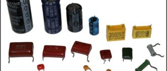
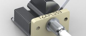
Samples of different types of capacitor devices
The concept of capacity, measurement rules
This value shows how many electrons (or other charged particles) must move from one object to another to obtain the required voltage value. The latter occurs because when particles move between objects, a potential difference is formed.
The unit of measurement of the capacitive value is the farad (in writing it is indicated by the capital Cyrillic letter F). When transferring a charge of 1 Coulomb, the voltage changes by 1 Volt, the value of the capacitance between the transferred objects is 1 Farad. The formula for the dependence of capacitance on voltage is as follows:
C (capacitance) = Q (charge)/U (voltage).
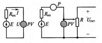
If a master is going to measure the capacitance of a capacitor used in an electronic circuit, he will need a device such as a multimeter. Even a budget device can cope with the task, and the greatest accuracy is demonstrated when working with film capacitor elements. For the most accurate measurements, you can use an immittance meter, but this device has a very high price (about 120 thousand rubles). When using a multimeter, you must adhere to the following algorithm:
- Disconnect the electrical circuit from the load source. Check the lack of power by setting the device to voltage measurement mode and placing the probes to the source: the indicator should be zero.
- Remove the charge from the capacitor passively (wait 20-30 minutes) or actively (using a resistor). For small elements you need a device with a resistance of more than 2 kOhm. It is better not to work with fairly large capacitors (for example, in cameras and household appliances) at home without preparation - they accumulate a dangerously high charge. To discharge such an element, a 20 kOhm and 5 W resistor is required, connected through an insulated wire with a diameter of 3.3 mm2, designed for operation at voltages up to 600 V.
- Disconnect the capacitor from the circuit. After this, put the multimeter in capacitance measurement mode. If the device is equipped with several adjustment ranges, you need to set the one that is most likely to be correct (you can navigate by the markings). If there is a Rel key, you need to press it so that the container comes off the probe elements.
- The probes are placed at the terminals of the capacitor. When testing polarized elements, it is imperative to observe polarity. Now you need to wait for the data to be displayed on the display. If the word overload (or OL) is displayed, the indicator is too high for detection by this device or in this range (in the second case, you need to select a different range).
Important! Do not connect the multimeter to a capacitor element whose body has punctures or bulging spots. Such elements should not be used at all - they can explode when power is connected.
The process of measuring capacitance of a capacitor with a multimeter
Electrical capacity
Electrical capacity is a scalar quantity that characterizes the ability of a conductor to accumulate electrical charge.
Electrical capacity:
- does not depend on q and U;
- depends on the geometric dimensions of the conductor, their shape, relative position, and electrical properties of the medium between the conductors.
The electrical capacitance of the conductor is called. the ratio of the charge of a conductor to its potential:
SI unit of capacitance: F (farad)
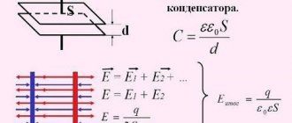
A capacitor has the property of accumulating and storing electrical energy. A capacitor is a system of two conductors separated by a dielectric layer, the thickness of which is small compared to the size of the conductors. The conductors are called capacitor plates. If the charges of the capacitor plates are equal in magnitude and opposite in sign, then the charge of the capacitor is understood as the absolute value of the charge of one of its plates.
The electrical capacity of a capacitor is the ratio of the charge of the capacitor to the potential difference between the plates. The main components of electrical capacity are presented in the figure below:
The main components of electrical capacity.
Designation on electrical diagrams:
- The entire electric field is concentrated inside the capacitor.
- The charge of a capacitor is the absolute value of the charge on one of the capacitor plates.
Types of capacitors:
- by type of dielectric - air, mica, ceramic, electrolytic.
- The shape of the plates is flat and spherical.
- according to the capacity - constant, variable (adjustable).
Electrical capacity.
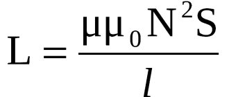
Electrical capacitance of a flat capacitor
where S is the area of the plate (plating) of the capacitor
- d - distance between plates
- εо - electrical constant
ε is the dielectric constant of the dielectric
A capacitor is a system of charged bodies that has energy.
Energy of any capacitor:
where C is the capacitance of the capacitor, (F) W is the energy (J) q is the charge of the capacitor, (C) U is the voltage on the capacitor plates, (V
The energy is equal to the work done by the electric field when the plates of the capacitor are brought close together, or the work to separate positive and negative charges necessary when charging the capacitor. Capacitors are used to store electrical energy and use it during rapid discharge (photoflash), to separate DC and AC circuits, in radio engineering: oscillating circuit, rectifier and other radio-electronic devices.
Capacitor, device with standardized capacity
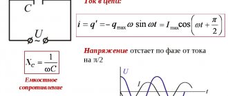
Current work - how is it measured?
This device is specially designed to change the voltage indicator in accordance with the accumulated charge. Different objects can have capacitor properties, but the main difference between a device is the presence of a fixed capacitance. When a charge of 1 Coulomb appears between the plates of an element with a capacity of 1 F, a voltage of 1 V arises between them.
Important! Novice circuit designers often make mistakes based on ignoring the impossibility of instantly changing the voltage on a device. If a transistor connected to a capacitor opens as quickly as possible, it will overheat or even burn out. When the terminals of a charged device are shorted, the current will be very high, but still not infinite. It is limited by the resistance of the element and its output parts.
The devices are used not only in radio electronics, but also, for example, when working with engines. When using a starting capacitor and an additional winding for 1 kW of power, 70 microfarads of capacitance will be required. Knowing this, you can calculate the total amount of capacity required.
Electric capacitor
A device designed to store electrical charges is called an electrical capacitor.
Figure 1. Model of a simple capacitor
The capacitor consists of two metal plates (plates) separated by a dielectric layer. To charge a capacitor, you need to connect its plates to the poles of an electric machine. Opposite charges accumulated on the capacitor plates are interconnected by an electric field. Closely spaced capacitor plates, influencing one another, make it possible to obtain a large electric charge on the plates with a relatively low potential difference between the plates. The electrical capacitance of a capacitor is the ratio of the charge of the capacitor to the potential difference between its plates:
As measurements show, the capacitance of the capacitor will increase if the surface of the plates is increased or brought closer to one another. The capacitance of the capacitor is also influenced by the dielectric material. The greater the electrical permittivity of the dielectric, the greater the capacitance of the capacitor compared to the capacitance of the same capacitor, in which the dielectric is emptiness (air). When choosing a dielectric for a capacitor, you need to strive to ensure that the dielectric has high electrical strength (good insulating qualities). A bad dielectric leads to its breakdown and discharge of the capacitor. An imperfect dielectric will result in current leakage through it and gradual discharge of the capacitor.
Long high voltage transmission lines can be thought of as capacitor plates. The capacitance of a wire must be considered not only relative to another wire, but also relative to the ground, room walls and surrounding objects. Underwater and underground cables have significant capacity due to the close proximity of current-carrying conductors to each other.
Application area
Capacitor Capacitance: Unit of Measurement
This unit of measurement is used not only for the capacitance of capacitors, but also for other conductive elements (for example, wires). Since 1 farad is a fairly significant capacitance, small industrial capacitor elements often have values of hundredths, thousandths, etc. fractions of a farad, for example, microfarads are designated microfarads. For ionistor ultra-high-capacity elements, on the contrary, the indicator can be measured in kilofarads.
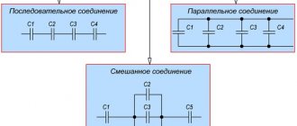
Multiples and submultiples
Most often in electronics, elements with small capacitances are used, which is why those starting to work with circuits have questions: pF is how many farads, 100 nf is how many microfarads, and so on. In this regard, you should have with you a table of conversion of one unit to another. The most commonly used submultiple units include:
- microfarad (μF) – 0.000001 F;
- nanofarad (nF) – 0.000000001 F;
- picofarad (pF) – 0.000000000001 F.
Of the multiple units, the kilofarad (kF) is used, equal to a thousand farads. Such indicators are typical for ionistors. For conventional capacitors, the capacitance is usually measured in a maximum of tens of farads.
In the Soviet Union, there was a tendency on electrical circuits and capacitor housings to indicate the capacitance value as a whole number (for example, 35). To mean picofarads, and a fraction with one digit after the decimal point meant microfarads. Letters were not used in such container markings. On modern domestic capacitors, when indicating the capacitance in picofarads, the measuring units are usually not written after the number. If the letters “mk” are indicated, microfarads are implied, if “n” - nanofarads are implied. Abroad they use markings made of colored stripes.
Table for converting some fractional capacitance units to others
Application of capacitors
This category of elements is very widely used in all areas of electronics and a number of other industries. Among the main areas of application are:
- television and sound reproducing equipment;
- radar devices (here capacitors help generate pulses and increase their power);
- telephone and telegraph devices - in them devices are used to separate types of circuits (by frequency, variability-constancy) and extinguish sparks in contacts;
- measuring electronic instruments;
- lasers (increasing pulse power);
- overvoltage protection in electrical power plants;
- electric welding work using a discharge;
- blocking machine-generated radio interference;
- starting electric motors and creating a phase shift in the additional winding;
- generators used during electrical testing to produce current and voltage pulses.
Capacitor element dimensions
Capacitor elements are used in a very wide range of areas - from printed circuit boards (miniature SMD components) to powerful motors and pulse generators. To correctly select a capacitor, you need to be able to decipher the markings and symbols on the diagrams, in particular, navigate the symbols of device capacitance.
Electrolytic capacitors
Electrolytic capacitors are also used in radio engineering. These capacitors are manufactured in two types: liquid and dry. Both types of capacitors use oxidized aluminum. By special electrochemical treatment, a thin (of the order of several tens of microns) layer of aluminum oxide Al2O3 is obtained on the surface of aluminum, representing the so-called oxide insulation of aluminum. Oxide insulation has electrical insulating properties, and is also mechanically strong, heat resistant, but hygroscopic.
In liquid electrolytic capacitors, an oxidized aluminum plate is placed inside a metal case that serves as a second plate. An electrolyte consisting of a solution of boric acid with some impurities is poured into the housing.
Dry electrolytic capacitors are made by folding three strips. One tape is oxidized aluminum foil (a thinly rolled sheet of metal). The other plate is an aluminum foil strip. A paper or gauze tape impregnated with a viscous electrolyte is placed between two metal strips. Tightly rolled tapes are placed in an aluminum casing and filled with bitumen. A thin oxide insulating layer with high electrical permittivity (ε = 9) makes it possible to obtain cheap capacitors with a high specific capacitance.
Video about the design of an electrolytic capacitor:
https://youtube.com/watch?v=tuVEW69oXuw