Electrical laboratory » Electrical laboratory services » Measurement techniques » Methodology for testing lightning protection systems
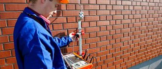
Our electrical laboratory specialists will check the lightning protection of chimneys, industrial, administrative or residential buildings. We will check the condition of the lightning rod, the connection of the lightning rod with the down conductor and the down conductor with the lightning protection grounding circuit. All work is performed with high quality and in a short time. It is very important to carry out a lightning protection check with the preparation of a “lightning protection check report” annually, before the start of a thunderstorm period. For any questions, please contact our office.
1. General Provisions
Tests of lightning protection systems for buildings and structures are carried out to verify their compliance with design solutions and requirements of the PUE (Chapter 4.2), PTEEP (Chapter 2.8), instructions for the installation of lightning protection of buildings and structures (RD 34.21.122-87).
Technical events
The list of necessary technical measures is determined by the person who allows the work together with the manufacturer in accordance with the requirements of SNiP 12-03-99.
When inspecting and checking the condition of lightning rods and down conductors on the roofs of buildings and structures, it is necessary to use installer safety belts. If the length of the belt sling is insufficient, it is necessary to use a safety rope previously secured to the building structure. In this case, one of the persons conducting the tests slowly lowers or tightens the safety rope. When checking welded joints of external current conductors and the design of lightning rods, the tool (hammer) must be tied to avoid falling. When a thunderstorm approaches, all work must be stopped and the team removed from the workplace.
Standardized values
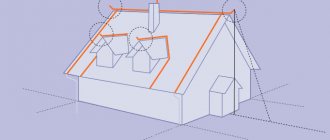
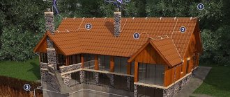
Protection against direct lightning strikes of buildings and structures classified as category I according to lightning protection devices must be carried out using free-standing rod or cable lightning rods
Protection against direct lightning strikes of buildings and structures classified as lightning protection categories II and III, with a non-metallic roof, must be carried out by separate rod or cable lightning rods or installed on the protected object.
When the roof slope is no more than 1:8, a lightning rod can be used as a lightning rod, made of steel wire with a diameter of at least 6 mm with a cell pitch for protection category II of no more than 6x6 m and 12x12 m for II I laid to grounding conductors no less than through 25 m along the perimeter of the building, they should be located no closer than 3 m from the entrances to buildings and in places inaccessible to the touch of people and animals. protection categories. Down conductors from a metal roof or lightning protection mesh must be
In all of the above cases, reinforced concrete building foundations should additionally be used as natural grounding conductors for lightning protection systems.
The dimensions of lightning rods, down conductors and grounding elements are given in Table 1.
TABLE 1.
| Shape of lightning rods, down conductors | Outside | In the ground |
| Rod lightning rods (steel) - cross-section no less - length not less | 100 mm2 200 mm | — — |
| Cable lightning rods (multi-wire steel rope) - cross-section no less - length | 35 mm2 depending on the protection zone | — — |
| Round down conductors and jumpers (steel) - diameter not less | 6 mm | — |
| Round vertical electrodes (steel) - diameter not less | — | 10 mm |
| Round horizontal electrodes (steel) *—diameter no less | — | 10 mm |
| Rectangular down conductors and grounding conductors (steel) - cross-section no less - thickness not less | 48 mm2 4 mm | 160 mm2 4 mm |
*Only for equalizing potentials inside buildings and for laying external contours at the bottom of the pit along the perimeter of the building. Connections of lightning rods with down conductors and down conductors with grounding conductors must be made by welding, and if hot work is not allowed, by bolted connections with a transition resistance of no more than 0.05 Ohm. Welds should not have cracks, burns, lack of penetration of more than 10% of the length of the seam, unfilled craters and undercuts. The surface of the seam should be uniformly scaly, without sagging. The length of the weld must be: for a design of round sections at least 6d (d is the diameter of the lightning rod, down conductor, grounding conductor), rectangular - 2 V, where B is the width of the steel strip of lightning protection system structures (clause 3.2 of VSN 164-82, GOST 10434-82, SNiP Sh-33-76 section II).
Lightning protection systems are tested:
- before putting them into operation
- for buildings and structures of protection category I and II at least once a year
- for buildings and structures of protection category III at least once every 3 years
At the same time, monitoring of the transient resistance of bolted connections of lightning protection systems should be carried out annually with the beginning of the thunderstorm season.
Lightning protection devices for buildings and structures must be tested, accepted and put into operation before finishing work begins.
Conditions for the examination
Scheduled tests are carried out before the start of the thunderstorm season. A visual inspection of the external lightning protection elements of an object should be carried out in clear, dry weather with low or normal relative air humidity.
Measurement of the resistance of the system's grounding loops during introductory and routine checks is carried out in conditions where the soil has the greatest electrical resistance in order to obtain maximum accuracy and reliability of the measurement results. Such conditions climatically correspond to moments of deep freezing in winter or the driest periods in spring and summer.
Testing.
Testing lightning protection systems includes the following stages:
- verification of compliance of the lightning protection system with design documentation, validity of the protection zone and compliance of the lightning protection system design with the requirements of RD 34.21.122-87
- visual inspection of the integrity and corrosion protection of visible parts of lightning rods, down conductors and contacts between them
- testing the integrity and mechanical strength of welded joints of lightning protection systems (carried out by tapping the welded joints with a hammer)
- measurement of transient resistance of bolted connections (according to the method of measuring the resistance of grounding conductors and grounding devices)
- measurement of the resistance of grounding conductors of free-standing lightning rods (according to the method of measuring the resistance of grounding conductors and grounding devices). The value of this resistance should not exceed more than five times the measurement results during acceptance tests. If the grounding conductor simultaneously performs the functions of protective (working) grounding of electrical installations of a building (structure) and grounding of the lightning protection system, additional measurement of its resistance is not required
Measurement methods
5.1. Measurement method using the MRU-101 device.
5.1.1 Conditions for carrying out measurements and obtaining correct results
To perform measurements correctly, several conditions must be met. The meter automatically stops the measurement procedure if the following abnormal situations are detected:
| Situation | Display symbols | Explanations |
| Noise voltage exceeds 24V | LIMIT and UN | |
| Noise voltage exceeds 40V | LIMIT and OFL a long beep sounds | |
| No current measurement | -r- together with the test socket symbol | Lack of connection of test leads of the required resistance or test leads not connected to the test leads |
| The resistance of the test leads exceeds 50 kOhm | LIMIT together with the resistance value of the test probe in the additional display field | Reduce the resistance value of the measuring probe or increase the soil moisture near the probe |
| Meters are out of range | OFL |
Additionally, the meter reports situations in which the measurement result cannot be considered correct:
| Situation | Display symbols | Explanations |
| Measurement error due to probe resistance deviation of more than 30% | LIMIT | |
| Battery cells are dead | BAT |
After turning on the meter with the R key, as well as after selecting a function with the rotary switch, the noise voltage value is displayed on the display.
If the noise voltage exceeds 24 V, then it is not possible to perform a measurement; in this situation, it is necessary to check whether the test leads are connected to the device, whether the power cable is connected to the network, whether there is a short circuit or a violation of the electrical insulation of the test leads, which may interfere with measurements.
ATTENTION! The meter is designed to operate at noise voltages less than 40 V. Applying more than 40 V to any test jacks may damage the meter.
The measurement starts after pressing the START key.
The device performs a measurement cycle, and if there is none of the reasons for blocking described earlier. During measurement, the main field of the display displays the symbols D-D - transmission of signals from the version of this measurement stage, and in the field the current values of the parameters measured in this meter mode. After the measurement is completed, the values of the resistance value and the resistance of the test probe or soil resistivity are displayed. Other meter parameters can be displayed by pressing the SEL key.
The meter automatically selects the measuring range for each function.
5.1.2 Measuring the resistance of a lightning protection system using a three-pole circuit.
The three-pole circuit is the main circuit for measuring the resistance of lightning protection devices . The procedure is:
- Connect the ground electrode to the measuring socket of the meter, marked as “E” (Fig. 1)
- Drive the current measuring probe into the ground at a distance exceeding 40 m from the system under study, and connect the measuring wire to the measuring socket “H” of the meter
- Drive the potential pound test probe at a distance greater than 20 m from the system under test and connect it to the test socket “S”. The ground electrode being tested, the current probe and the potential probe must be lined up in one line
- Set the rotary function switch to position RE Зр
- Press the START key
- Take readings of the resistance of the grounding device RE, as well as the resistance of the measuring probes Rs and Rh. Specific values can be read from the main display field after pressing the SEL key
- Repeat the measurements (according to paragraphs 5 and 6) after moving the potential measuring probe 1 m to the system being measured. If the measurement results differ by more than 3%, the distance from the current probe to the system under test should be increased significantly and the measurements should be repeated. The optimal position of the potential probe is 62% of the distance between the current probe and the system under study
Figure 1. Three-terminal circuit for measuring resistance
Particular attention should be paid to the quality of the connection between the system under study and the test leads. The contact area must be free of paint, rust, etc.
If the resistance of the meter probes is too high, the measured ground resistance will have an additional error.
A particularly large measurement error is observed when a small value of the grounding device is measured, which has free contact with the ground (this situation is observed when the lightning rod is made as a good electrode, while the upper level of the pound is dry and has poor conductivity).
Under this condition, the ratio of the resistance of the measuring probes to the resistance of the ground electrode under study is very large, and, as a consequence, the error depends on this ratio.
Then, according to the formula given in the Technical Data appendix, calculations can be made to evaluate the effect of the resistance of the test leads, which is ensured by using the diagram given in the same appendix.
The contact of the measuring probes with the ground can be improved, for example, by moistening the place where the probe is installed in the ground with water or by moving the probe to another location on the soil surface.
The test lead must also be checked to see if the insulation is damaged or if the contact with the probe terminal is broken, if the clamp is connected to the test probe, if the contact is damaged by corrosion.
In most cases, the measurement accuracy is sufficient. However, one must be aware of the magnitude of error resulting from the measurement.
What does the document include?
The protocol contains 3 components:
- Visual inspection data (Protocol No. 1)
- Checking transient resistance (Protocol No. 2)
- Checking the resistance of grounding devices (Protocol No. 3)
Also attached to it:
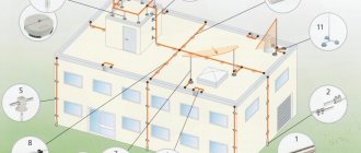
- lightning protection diagram indicating measurement points;
- copies of the registration (certification) certificate of the electrical laboratory;
- certificates of verification for the control and measuring instruments used to make the measurements;
- other necessary documents, if required (certificates, certifications of laboratory managers, engineers and others).
Visual control protocol No. 1
Contains the following items:
- Analysis of design documentation
- Checking the compliance of electrical installations (lightning protection part, down conductors, grounding conductors) with the regulatory framework and design. The presentation is performed in the form of a table.
- Found violations or comments
- Conclusion on acceptance or further operation of the lightning protection and grounding system
During the inspection it is recommended:
- visually assess the condition of all components, whether lightning rods and down conductors are damaged, whether they are securely connected to the system circuit, check the condition of all fasteners within the overall design of the lightning protection system;
- identify elements that require replacement or repair due to a violation of their mechanical strength;
- determine elements with corrosion, as well as the degree of its impact on the corresponding element;
- check the executive diagram of the lightning protection system with the current one;
- check the availability of the necessary documentation for lightning protection devices.
Protocol No. 2 for checking transient resistances
Measurements are performed in sequence from the lightning protection equipment to the grounding device, usually at the points where the connecting components (holders, terminals, etc.) are located between the individual components of the lightning protection system, as well as where it is in contact with the elements of the structure.
The results are recorded in the following table
The protocol also contains mandatory data:
- type of tests (acceptance, comparison, control tests, operational, for certification purposes);
- parameters of temperature, air humidity and pressure;
- data about the measuring device (type, serial number, metrological characteristics, verification dates, certificate number and the body that issued it).
Conclusions and conclusions regarding the compliance or non-compliance of the obtained parameters with the requirements of the rules.
Protocol No. 3 for checking the resistance of the grounding device
Contains items:
- Climatic conditions during measurements
- Purpose of inspection (acceptance, control, operational tests)
- Standard measurement base (RD, SO, PUE)
- Type and nature of soil
- Rated voltage of the electrical installation (up to 1000V, up to and over 1000V, over 1000V)
- Neutral mode (isolated, grounded)
- Soil resistivity
- The measurement results are displayed in the following table
Sometimes the table is supplemented with standard resistance data (permissible value, correction factor and final normalized value).
9. Table with measuring device data
10. Conclusion on the compliance of the grounding device with the requirements of the rules.
In conclusion, we offer you a couple of ready-made examples of Prokotlov No. 3 for checking the resistance of the grounding device in .doc format
Interesting materials on this topic:
Lightning protection passport
The lightning protection passport is practically no different from the protocol. What does it include? When is certification required? And also about how the corresponding measurement protocols are filled in.
Norms, rules and GOSTs for lightning protection - regulatory documents
On Russian standards in the field of lightning protection. A group of IEC standards and their comparison with domestic ones.
Lightning protection grounding resistance
What should be the maximum resistance for different lightning protection categories? Table of resistivity of various soils. About measuring ground resistance and frequency of checks.
5.1.3 Measuring the resistance of a lightning protection system using a four-pole circuit
In the event that it is necessary to perform a measurement without additional error due to the resistance of the test leads, a four-pole circuit is used.
To measure the system resistance you need:
- Connect the lightning rod to the measuring sockets of the meter, marked as “E” and “ES” respectively (Fig. 2)
- Install the current probe into the ground at a distance of more than 40 m from the point of connection to the lightning protection system and connect it to socket “H”
- Place the potential probe into the ground at a distance of 20 m from the system being measured, connected to socket “S”. The ground electrode (current and potential) and the measuring probes must be lined up in one line
- The rotary function switch must be set to position RE 4p
- Press the START key
- Take readings of the ground resistance value, as well as the resistances of the measuring probes Rs and RH. Specific values can be read from the main display field by pressing the SEL key
- Repeat the measurements (according to paragraphs 5 and 6) after moving the potential measuring probe 1 m further to the system being measured. If the measurement results differ by more than 3%, then the distance of the current measuring probe to the test subject is significantly increased and the measurements are repeated. The optimal position of the potential measuring probe is 62% of the distance between the current probe and the lightning protection system under study
Figure 2. Four-pole circuit for measuring the resistance of a lightning protection system
Types of lightning protection checks
Checks of lightning protection components are divided into one-time (for example, a test at the end of system installation), control (carried out on a schedule) and extraordinary.
- One-time. Performed upon completion of the installation of the system, in case of damage to the structure on which it is installed, during repair of the system, as well as during work to change its circuit, re-equipment of circuits;
- Extraordinary. Carried out after severe thunderstorms and natural phenomena (for example, earthquakes, floods, etc.), without carrying out resistance measurements, by visual inspection;
- Tests. They include a full cycle of control measures, with changes in system parameters according to an established plan.
Test facilities and equipment
The list of necessary testing tools and equipment is determined by the permitter together with the manufacturer of the work. In general, a set of devices, tools, and protective equipment should include the following:
- assembly line safety belts, safety ropes, safety helmets, ladders;
- device MRU-101
- hammer (weight 400 gr.)
- calipers
- tape measure 3 m
Safe working practices
Work on checking lightning protection systems of buildings is carried out according to a permit or by order. The type of work registration is determined by the employee who has the right to issue orders and orders. Persons from electrical technical personnel who are at least 18 years old, trained and certified in knowledge of safety regulations, PTEEP and this technique, provided with tools, personal protective equipment, and special clothing are allowed to work.
The team must consist of at least two people:
- a work performer with an electrical safety group of at least III
- a member of a team with an electrical safety group of at least III
These persons must undergo a medical examination for admission to steeplejack work and a knowledge test of SNiP 12-03-99 in the scope of the safety requirements for steeplejack work. A special entry is made about permission to carry out steeplejack work in the knowledge test log and in the certificate of verification of values on the page “Certificate for the right to carry out special work.”
Based on the measurement results, a protocol of the established form is drawn up. Persons who have committed violations of safety regulations or PTEEP, as well as those who have distorted the reliability and accuracy of measurements, are liable in accordance with the legislation and regulations on the mobile electrical laboratory.