Any resource, including electricity, needs transportation and redistribution. Unlike oil or coal, electricity is transmitted through power transmission lines (PTLs), which are mostly overhead lines (OHLs). These channels, due to economic feasibility, involve the transit of energy of enormous power.
To bring the characteristics of electricity into line with the parameters of the electrical networks of end consumers, as well as for its distribution, transformer substations are used.
Knowledge of the issue of lightning protection of transformer substations will help not only prevent financial damage from atmospheric electricity, but also save people’s lives.
Lightning hazard
Exceeding the operating voltage (overvoltage) as a result of a lightning strike can occur in two ways. Direct strike overvoltage (DSO) occurs when lightning directly strikes a substation. The induced one occurs as a result of an impact on the ground near the object.
Despite the short duration of the impact (about 100 microseconds), the damage can be quite significant. In addition to the fact that lightning has colossal voltage, the discharge temperature in the main channel can reach 30,000°C. Of course, the destruction of a substation or its elements can be quite significant.
Overvoltage in an installation can be caused by a lightning strike to the section of overhead line connected to it. Therefore, lightning protection of power lines also refers to a set of measures to protect substations from lightning.
In general, the following main reasons for the need to equip facilities with lightning protection devices can be identified:
- if the substation is located in a separate building, its destruction is prevented;
- protection from equipment destruction, which significantly increases its service life;
- ensuring stable power supply to consumers at the substation.
Here we can add a reduction in the level of injury to personnel. This means that lightning protection of the substation is necessary and mandatory in accordance with current legal requirements (PUE).
These rules allow only 20 and 35 kV substations equipped with transformers with a power of less than 1.6 kV not to be protected. It is also permitted not to equip substations and outdoor switchgear with lightning protection in climatic zones where the number of thunderstorm hours does not exceed 20.
Instructions for installing lightning protection added problems to designers
Recently, the problem of lightning protection has become increasingly urgent. In addition to protecting important objects from a direct lightning strike (external lightning protection devices), the requirements for internal lightning protection devices that provide protection from secondary lightning effects have increased.
In 2003, the “Instructions for lightning protection of buildings, structures and industrial communications” SO 153-34.21.122-2003 came into force. Our Moscow authors believe that the new document was unable to resolve the complex issues facing designers.
Mikhail Kuznetsov
, Ph.D.
Mikhail Matveev
, Ph.D.
Sergey Noskov
EZOP LLC, Moscow
Currently, a large number of facilities with increased requirements for lightning protection are being built and reconstructed: power plants (PP), especially nuclear power plants (NPP), substations (PS), facilities in the oil and gas industry, transport, communications, etc.
The functioning of many objects today is ensured by microprocessor (MP) equipment that is sensitive to pulsed electromagnetic interference (arising, among other things, during a lightning discharge). MP equipment performs more and more important functions. For example, it is already being installed as core elements of control and safety systems for nuclear reactors. Therefore, the concept of “lightning protection” in relation to the modern situation has expanded. Lightning protection can be divided into two interrelated components: protection against primary and secondary manifestations of lightning.
Protection from primary manifestations includes only an external lightning protection and grounding system, which ensures the actual protection of the facility from direct discharges (which can lead to death, damage to main equipment, fires, explosions, etc.) and diversion of the main part of the lightning current into the ground electrode. Protection against secondary manifestations of lightning includes means that protect sensitive equipment and its circuits from pulsed potential differences between “grounds” that occur during a nearby lightning discharge. Protection against secondary manifestations of lightning also includes means of shielding electromagnetic fields affecting equipment and its circuits.
Existing normative and technical documentation for lightning protection
Increased requirements for the organization of lightning protection require adequate reflection at the level of scientific and technical documentation. Traditionally used documents on the design of lightning protection systems, for example, RD 34.21.122-87 “Instructions for the installation of lightning protection of buildings and structures” (hereinafter Instruction - 1), made it possible to design a lightning protection system in such a way as to sufficiently protect the object from the primary manifestations of lightning: direct lightning strikes, ceilings, etc.
At the same time, the issues of protecting MF equipment and cable lines from secondary manifestations of lightning strikes were poorly considered. Therefore, there is a long overdue need to create a document regulating the protection of MP equipment and its circuits from overvoltages and fields that arise when lightning current flows through the elements of lightning protection systems and grounding devices. It was assumed that the new document - “Instructions for lightning protection of buildings, structures and industrial communications” SO 153-34.21.122-2003 (hereinafter referred to as Instruction 2) would resolve the accumulated issues. Moreover, by the time of its release, foreign standards for lightning protection already existed (IEC 61312 and IEC 61024). The domestic document should ideally have used and specified IEC materials, since, firstly, abroad the problems of lightning protection and EMC in general have been worked out in more detail than in Russia, and, secondly, by the time Instruction 2 was issued, sufficient experience should have accumulated use of these IEC standards. However, it is hardly an exaggeration to say that Instruction 2 did not live up to these expectations.
Already a quick glance at Instruction 2, one notices the much smaller volume of the section on protection against secondary lightning manifestations compared to the IEC. The only thing that has been done is that individual sections from IEC 61312 have been presented, for example, basic information has been given on the zone concept of protection, shielding and grounding. The presentation is carried out with minimal detail, which makes it difficult to apply the provisions of Instruction 2 in design practice. Not only did it not bring the recommendations of IEC 61312 to the level of specificity that would allow the document to be effectively used in design practice, but it also lost many of the positive features of Instruction 1.
For example, Instruction 2 does not contain a method for determining the minimum distance from structures with lightning rods to protected objects under the conditions of absence of overlap (secondary lightning discharge).
As a result, the document expected by the designers, no matter how offensive it may sound, was first published in the West (IEC-62305 [3]). This voluminous (5 volumes!) standard covers many aspects of protection from both primary and secondary manifestations of lightning and provides detailed recommendations that can be used without additional research. Of course, IEC-62305 is not without its drawbacks. Thus, in the methodology for estimating the average annual number of lightning strikes on an object, empirical coefficients for the location of objects are proposed, the use of which does not always give correct results [6]. But overall, this document is much more detailed and logical than Instruction 2.
FEATURES SO 153-34.21.122-2003
Document status
In order not to be unfounded, in this article we will look at some of the problems associated with Instruction 2. Actually, the issue is the status of the document. After the release of Instruction 2 in 2003, a controversial situation arose. The previously used Instruction 1 (and the industry documents based on it) was not formally canceled.
The very first phrase of Instruction 2: “The Instruction applies to all types of buildings, structures and industrial communications, regardless of departmental affiliation and form of ownership” turns out to be more than a bold statement, considering that the document was approved by order of the Ministry of Energy and is precisely an industry standard.
As practice has shown, in other industries this document is poorly used. But even the use of Instruction 2 in the electric power industry is not always possible.
Let's consider an example of a reconstructed facility (ES or PS), on which part of the outdoor switchgear is being completed. Here is the quote: “The instructions are intended for use in the development of projects, construction, operation, as well as in the reconstruction of buildings, structures and industrial communications.” Then the formally existing part of the object (which was designed according to earlier documents and may not meet the requirements of Instruction 2) must be reconstructed, which is not always realistic.
But even if the existing part of the facility remains unchanged, lightning protection of new cells must be designed in accordance with the requirements of Instruction 2. However, it is not clear how to calculate the interaction of lightning rods on the existing and new parts of the facility.
In addition to this confusion, it turned out that Instruction 2 not only does not meet modern requirements (issues of protection from secondary manifestations of lightning discharges, the specifics of lightning protection of explosive and fire-hazardous objects are almost not considered), but also has inaccuracies that complicate the design of lightning protection systems. Therefore, many industries continue to use Instruction 1 (for example, for the facilities of OJSC Gazprom) or have developed their own industry standards (for example, for the facilities of OJSC AK Transneft).
Level of facility protection and risk assessment
Let us first consider the most important issue on which the choice of specific technical solutions regarding lightning protection of a particular object depends. We are talking about a risk assessment procedure and the selection, based on its results, of the level of protection and lightning current parameters corresponding to the specifics of the facility.
Indeed, in most cases it is fundamentally impossible to provide 100% lightning protection of ground-based objects. However, it is possible to reduce the likelihood of accidents, damage or malfunctions in the operation of the facility as a whole and its subsystems to some acceptable minimum. At the same time, naturally, the costs of providing lightning protection should be linked to the possible risk.
Thus, there is no point in installing relatively expensive surge protection devices (SPDs) and providing special shielding for equipment whose cost is low and failure does not lead to serious consequences. In case of failure, it is much easier to replace such equipment, say, once every 40–50 years. But if such equipment ensures the uninterrupted operation of nuclear power plant safety systems, then protective measures that are much more expensive than the equipment itself will be justified.
The factors on the basis of which the requirements for protection reliability and the parameters of lightning current pulses are determined include: the importance of the object, the economic and social consequences of failures in its operation, the geometry and service life of it, lightning activity in the region of its location, etc. Guideline 2 provides only general guidance that a risk assessment should be carried out.
In this case, designers are asked to independently choose the level of protection. The proposed division of objects into types is too superficial: objects are divided into ordinary and special.
All power plants are classified as special ones, while substations apparently belong to ordinary facilities. It’s difficult to say more precisely, because... The table provided in the document is not exhaustive. Let's consider an example: a small hydroelectric power station or thermal power plant built at an enterprise in order to reduce external payments for electricity, on the one hand, and the 500 kV Chagino substation in Moscow, on the other. If a disruption in the operation of such a hydroelectric power station (TPP) creates short-term and removable inconveniences associated with the transition to external power supply to the enterprise, then an accident at a 500 kV system substation can, as practice has shown, have much more serious consequences.
From the text of Instruction 2, it also remains unclear with what level of protection the lightning protection system of power plants should be designed; only a range of 0.9–0.999 is given for all special facilities. But the cost of a lightning protection system designed with a protection level of 0.999 can be an order of magnitude higher than the cost of a lightning protection system designed with a protection level of 0.9.
For some reason, for special objects, even lightning current parameters are not given depending on the level of reliability. The table of reliability levels given for ordinary objects also does not answer the question of what level of reliability and what lightning current should be used in calculations for a specific object, and primarily for a substation. To understand the importance of answering this question, here are two examples.
1. For a 500 kV substation with linear dimensions of several hundred meters, located in an area with thunderstorm activity for 80–100 hours, the expected number of lightning strikes per year will be 2–3 discharges. If a lightning protection system with a reliability of 0.9 is designed for such a substation, on average, a lightning breakthrough through the lightning protection system will occur once every 5 years, i.e. impact directly on the primary equipment. Obviously, for such a substation, the lightning protection system must be built with a reliability of at least 0.99. In addition, using a lightning current value of 100 kA in calculations is not enough, since during the service life of the substation before complete reconstruction, at least one discharge into the substation territory with a current of 130 kA is likely [1, 3]. This assessment is made on the basis of data on the probability of lightning strikes with a given current value.
2. For a 110 kV substation, made, for example, on the basis of switchgear in building 15. 20 meters, located in the city center, in an area with 20–40 hours of thunderstorm activity, the expected number of lightning strikes is approximately one strike every 35 years. Naturally, for such a substation (taking into account the service life) a protection level of 0.8 will be more than sufficient, and the lightning current of 100 kA accepted according to Instruction 2 will be a clear “reset”. For example, a discharge with a current above 50 kA will occur on average once every 150–300 years (the estimate is based on the data given in [1, 3]). Naturally, for such a substation it is economically feasible to build a lightning protection system based on lower lightning currents (for example, 25–30 kA).
So, in order to design a lightning protection system correctly (with a sufficient level of reliability, but without “remortgaging”), it is necessary to assess the risks, select the level of lightning protection and determine the amplitude of the lightning current depending on the purpose of the protected object, the service life of the equipment at the site, the expected number of lightning breakthroughs and other factors. However, in Instruction 2 such a technique is completely absent.
Moreover, this document does not contain a methodology for determining the number of lightning discharges into an object depending on its geometric parameters (width, length, height of buildings and structures) and location. There is also no method for determining the accepted lightning current value. It should be noted that in IEC-62305 on lightning protection these issues are considered in much more detail, even in Instruction 1 some attention is paid to this issue.
Methodology for calculating protection zones
The most critical drawback of Instruction 2 is the actual methodology for calculating typical protection zones of rod and cable lightning rods. The proposed method only assumes the presence of lightning rods of the same height. There is a complete lack of methodology for calculating protection zones for lightning rods of different heights (rod, cable). Considering that in reality, lightning protection is often organized precisely by lightning rods of different heights (at a substation, even within one outdoor switchgear, lightning rods of different heights can be located - on portals and floodlight masts, for example), we can conclude that Instruction 2 is unsuitable for calculating lightning protection zones for many objects. It should be noted that Instruction 1 and especially IEC-62305 do not have this drawback.
The phrase from Instruction 2: “In the case of designing lightning protection for an ordinary facility, it is possible to determine protection zones by the protective angle or the rolling sphere method in accordance with the IEC standard (IEC 1024), provided that the design requirements of the IEC are more stringent than the requirements of the Instructions” does not solve the problem . Indeed, since the requirements of Instruction 2 for objects of different heights are absent, it will still not be possible to use the IEC standard.
Even for lightning rods of equal height, in order to justify using IEC, the designer will have to make calculations using both methods to compare the requirements and see which is more stringent. But the least fortunate are special facilities, the lightning protection of which can only be calculated according to Instruction 2 - after all, it is at such facilities that lightning rods, as a rule, have different heights. For example, pipes on the buildings of nuclear power plant units and lightning rods on outdoor switchgear of nuclear power plants differ in height by several times. It turns out that it is generally impossible to perform a correct calculation of lightning protection for nuclear power plants!
Another significant drawback of Instruction 2 is the lack of a methodology for calculating the lightning protection zone in the presence of more than two lightning rods. According to the proposed method, only the protection zone formed by a pair of lightning rods can be determined.
Obviously, if you build protection zones for three lightning rods only based on the overlap of lightning protection zones formed by each pair of them, then in most cases the zone located in the center of the triangle (formed by lightning rods) will not be covered.
Complete overlap of the specified zone will occur only if at the height of protection all pairwise formed zones intersect. This is possible, for example, for the case when the masts forming a regular triangle are located at a distance of no more than 2rx (two radii of single overlap zones at a given height, Fig. 1) from each other.
As an example, let's take the following case: if masts 30 meters high must cover an area 15 meters high, the masts (located, for example, at the vertices of an equilateral triangle) should be no more than 18 meters apart from each other at a protection level of 0.99 and at a distance of not more than 10 meters with a protection level of 0.999. In this case, you will have to literally stick the object with masts in order to protect it according to the given method. But then lightning rods will inevitably end up in close proximity to secondary circuits, locations of electronic equipment, etc., which in itself leads to serious problems.
It should be noted that in Instruction 1 the issue of constructing zones of several lightning rods (more than two) was resolved. Let us recall that it said the following: “The main condition for the protection of one or several objects of height hx with reliability corresponding to zones A and B is the fulfillment of the inequality rcx > 0 for all lightning rods taken in pairs.” This means that if each pair of lightning rods interacts at a given height (i.e., forms a common zone, and not two separate protection zones), then the zone between the pairwise zones will be blocked from a direct lightning strike at the same given height.
Inconsistencies between CO and IEC
Since when analyzing Instruction 2 one constantly has to refer to IEC-62305, it seems appropriate to cite their other inconsistencies in order to avoid such errors and inconsistencies when revising Instruction 2 and creating a new document on lightning protection. This is necessary, in particular, in order to unify methods in order to avoid misunderstandings that may arise during the design and construction of facilities abroad or the application of standard foreign developments in Russia.
Such inconsistencies include, for example, the following: Table No. 2.2 (Section No. 2) shows the following levels of protection against direct lightning strikes: Level I – 0.98; Level II – 0.95; Level III – 0.9; Level IV – 0.8.
In accordance with IEC 62305, the protection levels are as follows: Level I – 0.99; Level II – 0.97; Level III – 0.91; Level IV – 0.84.
By the way, it is easy to notice that the levels of protection according to IEC are in all cases higher than in Instruction 2.
Noteworthy is the discrepancy between the values of protection levels for ordinary (0.98; 0.95; 0.9; 0.8) and special objects (0.9; 0.99 and 0.999).
Considering that the methodology for calculating lightning protection zones is given only for protection levels of 0.9; 0.99 and 0.999, it remains a mystery how to calculate for levels 0.98; 0.95 and 0.8. Although Instruction 2 states that for ordinary objects the calculation method proposed in IEC 1024 can be used, but with the condition “that the design requirements of the International Electrotechnical Commission are more stringent than the requirements of this Instruction.” At the same time, it turns out to be impossible to determine which requirements are more stringent, since there are simply no requirements in the Instructions for the specified levels of protection!
Inconsistencies with IEC also include the values of some lightning current parameters given in Table 2.3 of Instruction 2. For example, the values of the average slope of the first lightning current pulse are incorrectly indicated (average slope di / dt30/ 90%, kA/μs): 200, 150 and 100. Correct values are ten times smaller: 20, 15 and 10 kA/µs. This contradiction is most likely just an error.
INACCURACIES AND GAPS
In general, the document in question is replete with factual errors, leading to the impossibility of using even those calculation methods that are presented in the document. The following is a list of such errors, which does not pretend to be complete:
1. Table 3.6 “Calculation of the parameters of the protection zone of a double rod lightning rod” provides a formula for determining Lc at a reliability of 0.999, in which the factor 10–3 is superfluous. In addition, the same table shows another formula (for reliability 0.99):
[2.25–0.01007(h–30)]h, in which the multiplier before the bracket is also questionable. Perhaps instead of 0.01007 there should be 0.0107, or in the previous formula instead of 0.0107 there should be 0.01007.
2. The phrase “For distances LcLLmax, the height hc is determined...” is constantly encountered, in which the relation for L is also erroneous. The correct way to write in this case is: LcLLmax. Significant shortcomings of the document include the following. In the proposed calculation methodology for lightning protection zones, the maximum height of lightning rods should not exceed 150 m.
The question arises: why exactly 150 m, and what to do if you need to protect a higher object? The document says that for this you need to use a special technique, but there is no link to it. Meanwhile, there are more and more objects with a height of more than 150 m (TV towers, skyscrapers, etc.). And here it is necessary not only to ensure protection of already constructed buildings from lightning, but also to provide for lightning protection measures during the construction process itself. Unfortunately, this aspect is also not covered in Instruction 2.
UNANSWERED QUESTIONS
Finally, let us dwell in more detail on what, unfortunately, is practically absent from Instruction 2: on the issues of protecting sensitive equipment and its circuits from secondary manifestations of lightning discharges with a level of detail that would allow a non-specialist in the field of EMC to carry out lightning protection projects. As practice has shown, taking into account EMC requirements when constructing complex lightning protection systems (including grounding systems, surge protection systems and electromagnetic fields) is currently vital.
Thus, at one of the largest oil industry enterprises in our country, the system of protection against direct lightning strikes was designed correctly (more precisely, according to the current normative and technical documentation), but protection against secondary manifestations of lightning was not carried out (Fig. 2a). Secondary circuits and installation sites for MF equipment fell into the zone of high impulse potential at the bases of lightning rods. This led to the fact that during one thunderstorm season, as a result of several lightning strikes on lightning rods, a significant part of the facility’s electronic equipment was disabled. In Fig. 2b shows another example of erroneous implementation of lightning protection.
Today it is obvious that the Lightning Protection Instructions should contain not only general words (like Instruction 2), but also specific recommendations and technical solutions, the implementation of which will protect sensitive microprocessor equipment and its circuits.
For example, Instruction 2 superficially examines the problem of protecting equipment from magnetic fields induced by lightning current. Information is provided that the metal structures of the building can be used as screens. Nothing is said about what to do if the building is brick, or if the shielding factor of the metal structures is not enough to attenuate the field to a level that is safe for the equipment. There are no specific recommendations for determining the shielding factor.
However, often when installing new sensitive equipment in existing buildings, the use of additional shielding is the only available way to combat pulsed magnetic fields.
The instructions for lightning protection must contain a detailed description of how to do this, so that the designer, depending on the situation, can choose the appropriate protection option: is the metal structure of the building sufficient or is it necessary to use additional shielding of the building or room itself; how to properly organize screening of premises; Is a mesh screen sufficient or is it necessary to use metal sheets. If it is not possible to shield the room or for economic reasons it is more profitable to place the equipment in shielding cabinets, how exactly to choose shielding cabinets. The question is serious, because many of the currently produced metal cabinets do not have shielding properties, since the presence of long gaps between the walls and the frame reduces the shielding effect to almost zero. All these questions must be given clear answers in the Lightning Protection Instructions. A similar situation has developed with recommendations regarding the grounding of protected objects and the creation of a protection system against surge voltages in circuits up to 1 kV. Instruction 2 provides only general recommendations on these issues. Little attention has been paid to methods of protection against surge voltages using special devices (surge protection devices), galvanic isolation, and shielding of sensitive equipment circuits [2, 5]. But the choice of the type of SPD, for example, is a very important issue. Thus, arresters cannot be installed in the measuring circuits of voltage transformers at substations, since when they are triggered, the shape of the useful signal may be distorted, but the installation of SPDs based on varistors in such circuits is possible, as was shown in [5]. It is worth noting that for facilities that do not have a single grounding device in the form of a grid (for example, many facilities in the gas industry), the use of SPDs is often one of the few effective ways to combat surge voltages. For example, IEC-62305 devotes almost 20 pages to the use of SPDs alone.
The same applies to the use of shielded cables with double-sided grounding of the shields for surge protection. In Instruction 2 it is only recommended to do this, but no quantitative characteristics are given. It also does not say in which cases this can be done, and in which such a measure may be insufficient or even lead to negative consequences. Research conducted by EZOP LLC has shown that such an event (if carried out correctly) makes it possible to reduce the overvoltages applied to the inputs of MP equipment several times (from 4 to 20 times, see [5]).
Instruction 2 practically does not touch upon the issues of linking the grounding system of lightning rods with the grounding of other objects. This issue is especially relevant for distributed large-area facilities, such as, for example, electrical substations (which, by the way, are the most numerous facilities in the electric power industry, for which this document was issued). But it is the correct choice of grounding schemes for lightning protection elements that often makes it possible to do without additional expensive measures to protect against secondary manifestations of lightning discharges [2, 4], including without the use of SPDs.
OFFERS
Thus, there is a need to begin work on creating a new document regulating the design of lightning protection systems taking into account modern requirements.
This task goes far beyond the scope of this article. But it is obvious that the new document should apply to the largest possible number of types of objects and provide the clearest possible solutions, rather than vague general provisions. The listed contradictions, inaccuracies and gaps must be eliminated.
The document must not contradict the IEC and must clearly distinguish between cases when it is necessary to comply with new requirements, and when it is sufficient to comply with the requirements of previously issued documents. And, of course, it is necessary to fully consider the issues of protection against secondary manifestations of a lightning discharge.
However, the question arises: is it possible to guarantee that the new document will be fundamentally better than the previous one, or will the situation with the RD of 1987 and the RD of 2003 repeat itself, forcing the designer to use the requirements of different documents?
It is hardly possible to give an exhaustive answer here. But I would like to remind you the following. In 2003, the release of Instruction 2 came as a surprise to much of the engineering community.
As far as is known, there was no publication or wide discussion of the draft document. Therefore, it seems absolutely necessary, in the case of developing a new document, to publish its draft well before adoption in order to comprehensively discuss comments and suggestions. And there will certainly be a lot of them.
LITERATURE
1. Sen PK Understanding Direct Lightning Stroke Shielding of Substances / PSERC Seminar Golden, Colorado, November 6, 2001. - Colorado School of Mines, 2002.
2. Kuznetsov M. B., Matveev M. V. Protection of MF equipment and its circuits on substation and power supply systems from secondary manifestations of lightning discharges // Elektro. – 2007. – No. 6.
3. IEC 62305. – Lightning Protection.
4. Kuznetsov M. B., Matveev M. V. An integrated approach to solving the problems of protecting MF equipment of power facilities from secondary manifestations of lightning discharges / Collection of proceedings of the First All-Russian Conference on Lightning Protection. – Novosibirsk, 2007.
5. Kuznetsov M.B., Kungurov D.A., Matveev M.V., Tarasov V.N. Problems of protecting the input circuits of relay protection and automation equipment from powerful pulse overvoltages // News of Electrical Engineering. – 2006. – No. 6(42).
6. Bazelyan E.M., reports / Collection of proceedings of the First All-Russian Conference on Lightning Protection. – Novosibirsk, 2007.
Protection against PUM
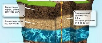
Buildings, substations, including open switchgears (OSD), overhead lines and other objects are protected from lightning strikes using a lightning rod or a complex of them. The device, invented in the mid-18th century, is still relevant today.
In general, lightning rods come in cable and rod types. The first of them are used to protect extended objects, such as bus bridges, from lightning, and are used relatively rarely. The latter are the most common and are capable of providing lightning protection for buildings, overhead power line supports and other objects.
A lightning rod, as the name suggests, is a device consisting of an air terminal, a current conductor and a grounding conductor. Located significantly higher than the other structural elements of the structure, at least 3 meters (PUE), it absorbs the lightning strike.
Introduction
The energy sector, or more precisely the part dealing with electrical energy, includes many electrical installations that require grounding to operate. Depending on the purpose of the object, it is important to organize the correct grounding device. It must perform the functions of protective grounding, which serves to ensure electrical safety, as well as the worker necessary to ensure the operation of electrical installations, including the purpose of protection against operational damage, for example, short circuit, and dangers arising from lightning strikes.
Grounding is necessary not only for the operation of electrical machines and devices, but also for the operation of automation and electronics devices, which contribute to the management and control of work processes, the protection of electrical installations from damage during accidents and malfunctions, as well as the prevention of accidents themselves. Otherwise, if the grounding is organized incorrectly, or is completely absent, there is a risk that, as a result of emergency situations, the electrical installation will be taken out of operation for the time necessary to detect and eliminate their cause. During this entire period, sometimes taking several hours or even days, consumers, starting from a residential building and ending with a district, city, or federal subject, will be without electricity. The consequence of power supply interruptions can be financial losses due to production downtime and threats associated with disruption of the life support sector.
To avoid power outages, it is important to ensure trouble-free operation of facilities for the production, conversion, transformation, transmission, distribution and consumption of electrical energy. This is ensured by many factors, including the organization of high-quality grounding that complies with regulatory documents.
Requirements for lightning rod
The lightning rod is made of steel. In order to withstand thermal loads when current flows, as well as the high temperature of the lightning itself, according to the PUE, its diameter must be more than 6 mm. The connection of the lightning rod to the current conductor must be made by welding them.
If this is not possible, then a threaded connection with a bolt and nut is acceptable. The diameter of the washers in this case must be increased. To avoid falling and resulting damage, the device must be firmly secured to a support or other supporting structure.
Lightning rods are usually fixed to existing metal structures. These can be floodlight masts, roofs of high-rise buildings, high points at the entrance to a substation.
The exception is transformer substations. Lightning receivers for lightning protection are not installed on them. If such a need arises, then the low-voltage windings are protected with valve arresters.
Substation lightning protection components
Providing lightning protection for electrical substations is one of the key requirements when constructing such facilities. This system diverts the electrical discharge generated after a lightning strike to the ground without contact with switchgear. Therefore, structurally, lightning protection of transformer substations can consist of three parts:
- lightning rod;
- protective circuit;
- substation grounding.
When switchgears are located inside a facility, they are only equipped with a protective circuit to prevent overvoltage. External protection is provided by the building itself. All three elements - lightning rod, protective circuit and grounding - are required only in cases where the substation is a separate structure.
Ground electrode
The down conductor is connected to the ground electrode – one of the most important parts of lightning protection. To save money, one grounding device is used as a grounding device, which meets the most stringent requirements of the following types of grounding:
lightning protection grounding;- working grounding (transformers, generators and other equipment);
- protective grounding ensuring the safety of people.
The lightning protection grounding device at substations is made of strips placed horizontally in the ground, which are connected to vertical electrodes going to the down conductor. All metal parts of the substation, including tank housings, switches, etc., must have contact with grounding. Only in this case is reliable lightning protection guaranteed.
Networks with voltages from 110 kW are made with a solidly grounded neutral, and substations of 35 kV and below are grounded through an arc suppression reactor.
All components of the lightning rod must have an anti-corrosion coating, which is usually galvanized. The number of devices on one structure, as well as their efficiency and protection zones are determined by appropriate calculations. Thus, protection of substations from direct lightning strikes is ensured using lightning rods.
Combining grounding for lightning protection with grounding for electrical installations
The need to electrically connect the grounding loop of lightning protection installed directly on the building with the grounding loop for electrical installations is prescribed in the current regulatory documents (PUE). We quote verbatim: “Grounding devices for protective grounding of electrical installations of buildings and structures and lightning protection of categories 2 and 3 of these buildings and structures, as a rule, should be common.” The 2nd and 3rd categories are the most common; the 1st category includes explosive objects for which increased lightning protection requirements are imposed. However, the presence of the phrase “as a rule” implies the possibility of exceptions.
Modern office and now residential buildings contain many life support engineering systems. It is difficult to imagine the absence of ventilation systems, fire extinguishing systems, video surveillance, access control, etc. Naturally, the designers of such systems have concerns that “delicate” electronics will fail as a result of lightning. At the same time, some doubts arise among practitioners about the feasibility of connecting the contours of two types of grounding and a desire arises “within the limits of the law” to design electrically unconnected groundings. Is this approach possible and will it actually improve the safety of electronic devices?
Protection against induced waves
Lightning protection of a substation in the event of an indirect lightning strike is provided by special devices that provide protection against surge voltage.
Considering that it is not known in advance where lightning will strike, all inputs and outputs of the substation are equipped with either surge arresters or more advanced surge arresters (OSL).
The principle of operation of a spark gap is based on the formation of an arc between two rod electrodes, one of which is grounded and the second is connected to a phase wire.
They are separated by a protective gap. When the latter breaks down (a spark appears), the entire electrical installation is switched off, providing its lightning protection.
A tubular spark gap is considered more effective, consisting of a gas-generating tube, ring and rod electrodes and two spark gaps, internal and external.
In the event of an overvoltage, the latter break through and an arc is formed, the high temperature of which starts the gas generator. Under pressure, the gas moves to the open end of the tube, which is enough to blow out the arc.
List of measures for grounding (grounding) and lightning protection
Design solutions for grounding and protective safety measures are made taking into account the requirements of the PUE, 7th edition, chapter 1.7.
The TN-S grounding system is adopted. The type of grounding system in electrical installations with voltages up to 1 kV is adopted TN-S; in electrical installations with voltages above 1 kV it is adopted with an insulated neutral. According to clause 1.7.50 of the PUE, 7th ed. To protect against electric shock in normal operation, the following direct contact protection measures are applied:
- basic insulation of live parts;
- fencing and shells;
- placement out of reach;
- ultra-low (low) voltage.
For additional protection against direct contact, differential circuit breakers with a rated differential switching current of no more than 30 mA are used.
Valve type arrester
An even more advanced lightning protection device against induced waves is a valve-type arrester. In addition to the gaps for sparking, it includes a sealed porcelain cover and resistors with a nonlinear current-voltage characteristic (VAC).
It is worth noting that, according to the PUE, there are restrictions on the maximum distance from the arrester to the substation transformers, ranging from 60 to 90 m, depending on the type of overhead line supports.
Arresters are used less and less to provide lightning protection for substations. More advanced devices are gradually occupying their niche. Their main advantages are the absence of spark gaps, small sizes, and deep limitation of overvoltages.
The principle of operation of the surge arrester is extremely simple. A varistor (non-linear resistor) behaves as a resistance until a threshold voltage is reached. Exceeding this value leads to the fact that the device maintains the voltage at a given level due to the branching of part of the current to the ground.
When using surge arresters as lightning protection, there are difficulties with the duration of holding the operating voltage and some others. But with the correct selection of the type of device, nonlinear lightning protection is most effective.
Why you need to contact Aleph-EM
The Aleph-EM company specializes in lightning protection, grounding, and cable heating systems. We work in one direction, in which we are constantly improving, and we are the first in Russia to introduce innovations. We cooperate with manufacturers of components and ready-made lightning protection systems: Dehn+Soehne, Citel, OBO Bettermann. We offer wholesale prices and will help you choose materials for your project.
With us you get:
- high level of protection against lightning strikes - the design is carried out by a team of engineers: architects, electricians for power and low-current networks, communications specialists, CAD engineers;
- design taking into account the type of soil, wind direction, we calculate each protrusion to ensure 100% coverage of the object with lightning protection;
- low price of lightning protection - we take into account the design features of the building, for example, metal masts or seam roofing, which can be used as a current collector.
We work all year round. Free site visit upon signing a contract. We also install lightning protection. When purchasing equipment, as well as developing a project in Aleph-EM, you receive a discount on installation.
Design stages
Preliminary selection (concept development):
- Determination of the lightning protection category of an object. According to regulatory documents RD 34.21.122-87 or SO 153-34.21.122-2003, we select the lightning protection class (I, II, III or IV);
- Selecting a lightning protection method (protective angle, rolling sphere or mesh) and type of grounding loop (focal, ring or foundation);
- Choice of material for system elements. Based on standards, taking into account aesthetic and economic considerations, as well as installation and environmental features (the most common are Al, Cu, galvanized or stainless steel);
- Determining locations for installing lightning rods and laying down conductors.
Equipment calculation:
- Lightning protection equipment - calculation of protection zones, selection of lightning protection system (rod, cable lightning rods or mesh, as well as their combination), determination of their diameters and lengths;
- Down conductors (calculation of quantity and diameter);
- Calculation of the number and installation locations of roofing and facade holders;
- Calculation of the ground loop.