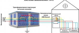
What is a grounding bus and how to install it
Most houses are equipped with old electrical transmission systems - that is, without grounding conductors. Such schemes are outdated and do not provide the proper level of security - when a large number of devices are connected to the network, the wiring may short out. The main tasks of the system are to turn off the mains voltage in case of current leaks and to create optimal conditions for the operation of household appliances. Some devices, in addition to having a grounding contact in the socket, require direct connection to a special bus using clamps. There are special clamps for this.
What is a ground bus
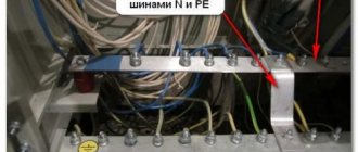
The grounding bus is installed on the input panel. It connects the wires coming from:
- protective house grounding;
- Electricity consumers;
- metal structures;
- housings and casings of electrical equipment.
A protective conductor PEN is connected to the grounding bus, which is connected to the VLI. Nuts and bolts are used to connect the working parts, but welding will be required to solve some problems. An example is welding a grounding conductor from plates and corners, as opposed to simply screwing it on, which ensures reliable contact between the parts. In factory-made copper pin-type grounding conductors, laser cutting is used, processing, and cutting metal with your own hands at a high level is impossible.
Do-it-yourself grounding of a private house
The most universal way to install a grounding loop is grounding from pipes with a flattened end. Ten holes with a diameter of five to eight millimeters are randomly drilled at the bottom of the pipe. In hot summer weather, you can pour a saline solution into these same holes (half a pack of salt in a five-liter bucket of filtered water) to keep the resistance level normal.
It is important to know: the grounding bus has the same structure as the lightning rod bus. But, under no circumstances should you use zinc layer for metal bonding, as it will rust immediately after the first rain.
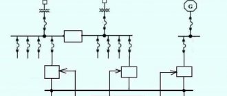
We are developing a scheme
As before any start of construction work, it is necessary to develop a grounding diagram that will guide you in the future.
There are two types of schemes:
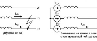
- Linear diagram. Metal pins are installed in one straight line, which are connected in series. But this system has a significant disadvantage - if the first jumper is damaged, the entire grounding system will instantly fail.
- Closed (triangular). Unlike the first scheme, it is more reliable and durable.
It is important to know: most experts recommend using a triangular grounding scheme for a private home, since the installation work is extremely simple, and it works several times better than a linear one (including the durability of the closed-loop system and its efficiency).
We prepare tools and materials
In order to make grounding with our own hands for a private house using tools we will need:
- Five to eight kilogram sledgehammer;
- Regular construction shovel;
- Welding apparatus and mask to protect the face and eyes.
Ground Measurement
In order to make sure how well the ground loop protects you, you need to take measurements. For this, professionals use a special device PKP - three. At home, it will not be possible to measure grounding, since the indicators will be inaccurate and incorrect. Therefore, you can buy or borrow this measuring device from someone.
It is important to know: using voltage from the electrical network, resistor voltage or milliammeter to ground grounding is dangerous for your life!
Installation work
- First you need to determine where exactly the ground loop will be located. You need to choose a closed and secluded place where neither a person nor an animal can pass (to avoid death).
It is important to know: if such a place is not found, and you do not want to spoil the beautiful landscape of your yard with bayonets, then you can organize a secret system by placing the grounding under artificial stones or under a garden sculpture.
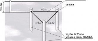
- Working with the earth. For example, in order to make a triangular contour, you need to use a shovel to dig out a triangle with sides up to two meters and a depth of up to seventy centimeters.
- So, let's get down to the most important thing - installation of the structure. The electrodes must be driven to a depth of up to two meters into the ground (only their tops should remain visible).
After all the electrodes have been driven in, you need to weld the metal plates to their tops to create a triangle-shaped frame.
At the end, the wires connected to the bus are connected.
Ground Testing
Well, now all the grounding is ready and all that remains is to carry out a test test. According to building rules, control fading must be made with a special device, the cost of which is quite high and there is no point in spending money on its purchase in order to use it once or twice.
Our folk craftsmen were able to come up with a folk method of peace that amazes with its accuracy. For this we need a regular lamp (with a power of at least 100 W). All you need to do is connect the lamp with one contact to ground and the other to phase. If in the end the light bulb burns brightly, then everything is in order with grounding, and it is not only effective, but also safe.
Copper busbar design
The grounding bus is a set of metal parts that ensure reliable contact between the electrical installation housing and the ground. Main components of the system:
- main bus GZSh;
- bends;
- ground wires;
- general outline.
Terminals, strips, grounding clamps according to PUE and GOST can only be made of copper and steel, regardless of the characteristics of the circuit and the type of electrical installation. In many ways, the effectiveness of the protective grounding device depends on the resistance.
The IEK grounding bus is usually a copper plate with a set of holes. The wires must be crimped with a connecting sleeve or cable lug. For fastening, grounding washers or a bolt and nut are used. The wires are masked.
Standard grounding bus connection diagram:
- ground loop;
- strip or wire from the circuit to the input panel
- grounding bus in the shield.
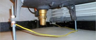
In private homes, the system is installed in a separate cabinet or water distribution device with protective components and automatic switches. If the input device is mounted on a pole, the bus will be mounted inside it. Remember to re-ground the PEN conductor outside the pole.
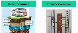
What does grounding consist of?
- External ground loop. It is located outside the premises, directly in the ground. It is a spatial structure of electrodes (grounding conductors) connected to each other by an inseparable conductor.
- Internal ground loop. A conductive bus located inside a building. Covers the perimeter of each room. All electrical installations are connected to this device. Instead of an internal circuit, a grounding shield can be installed.
- Grounding conductors. Connecting lines designed to connect electrical installations directly to the ground electrode, or internal ground loop.
Take a closer look at these components.
External or outer contour
The installation of the ground loop depends on external conditions. Before starting the calculation and completing the design drawing, you need to know the parameters of the soil in which the ground electrodes will be installed. If you have built a house yourself, these characteristics are known. Otherwise, it is better to call surveyors to obtain an opinion on the soil.
What types of soils are there, and how do they affect the quality of grounding? Approximate resistivity of each soil type. The lower it is, the better the conductivity.
- Plastic clay, peat = 20–30 Ωm m
- Plastic loam, ash soils, ash, classic garden soil = 30–40 Ohm m
- Chernozem, shales, semi-hard clay = 50–60 Ohm m
This is the best environment to install an external ground loop. The current flow resistance will be quite low even with low moisture content. And in these soils the natural humidity is usually above average.
Semi-solid loam, mixture of clay and sand, wet sandy loam - 100–150 Ohm m
The resistance is slightly higher, but at normal humidity the grounding parameters will not exceed the standards. If there is prolonged dry weather in the installation region, it is necessary to take measures to forcibly moisten the installation sites of ground electrodes.
Clay gravel, sandy loam, wet (constant) sand = 300–500 Ohm m
Gravel, rock, dry sand - even with high general humidity, grounding in such soil will be ineffective. To comply with standards, deep grounding will have to be installed.
Many facility owners, saving on matches, simply do not understand why a grounding loop is needed. Its task, when connecting a phase to the ground, is to ensure the maximum value of the short circuit current. Only in this case will the protective shutdown devices operate quickly. This cannot be achieved if the current flow resistance is high.
Having decided on the soil, you can choose the type, and most importantly, the size of the ground electrodes. Preliminary calculation of parameters can be performed using the formula:
The calculation is given for vertically installed grounding conductors.
Decoding the formula values:
- R0 is the resistance of one ground electrode (electrode) obtained after calculation in ohms.
- Rekv - soil resistivity, see information above.
- L is the total length of each electrode in the circuit.
- d is the diameter of the electrode (if the cross-section is circular).
- T is the calculated distance from the center of the electrode to the surface of the earth.
What does circuit resistance depend on?
The grounding terminal can show different values of grounding resistance - the total value is the sum of a set of parameters, including resistance on individual wires, a common busbar, and the ground contour. The value of these parameters decreases if metal parts have low resistance with high conductivity. An important parameter is the resistance of the soils through which currents flow (the lower it is, the better). Standards for maximum permissible values:
- for buildings with networks of 220, 380V - 30 Ohm;
- for generators, transformer substations – 4 Ohm.
Table of resistances by soil type.
Soils Ohm/m2 Granite stone 2000 Limestone 5050 Basalt 2000 Homogeneous gravel 800 Gravel with clay 300 Sandstones 1000 Wet pressed sandstone 800 Chernozem 200
The degree of soil conductivity increases sharply with increased soil moisture. It is necessary to take this into account when arranging a grounding system. Other parameters are the depth of the circuit, the materials used to manufacture the working parts, dimensions, and the number of electrodes. Elements of the grounding system are placed in the main busbar. Trouble-free operation of installations largely depends on the selected material and compliance with installation rules.
Ground loop materials
For the grounding of a private house to be effective, its resistance should not be more than 4 ohms. To do this, it is necessary to ensure good contact of the grounding conductors with the ground. The problem is that grounding resistance can only be measured with a special device. This procedure is carried out when putting the system into operation. If the parameters are worse, the act is not signed. Therefore, when doing the grounding of a private house or cottage with your own hands, try to strictly adhere to the technology.
Example of grounding for a private house
Pin parameters and materials
Grounding pins are usually made of ferrous metal. Most often, a rod with a cross-section of 16 mm or larger or a corner with parameters 50 * 50 * 5 mm is used (shelf 5 cm, metal thickness - 5 mm)
Please note that reinforcement cannot be used - its surface is hardened, which changes the distribution of currents, and in addition, in the ground it quickly rusts and collapses. What is needed is a rod, not reinforcement
Possible electrode profiles
Another option for arid regions is thick-walled metal pipes. Their lower part is flattened into a cone, and holes are drilled in the lower third. To install them, holes of the required length are drilled, since they cannot be driven in. When soils dry out and grounding parameters deteriorate, a saline solution is poured into the pipes to restore the dissipative capacity of the soil.
The length of the grounding rods is 2.5-3 meters. This is sufficient for most regions. More specifically there are two requirements:
- the grounding loop rod must extend into the ground below the freezing level by at least 60 cm (preferably 80-100 cm);
- in arid regions, at least 1/3 of the ground electrode should be in wet soils, so you also need to focus on the level of groundwater - if it is low, longer rods may be needed.
The most commonly used steel angle and strip
Specific grounding parameters can be calculated, but the results of a geological study are required. If you have any, you can order a calculation from a specialized organization.
Installation procedure for protective grounding
Protective grounding is a system of intentionally connecting iron parts of an electrical installation to the ground in order to increase the safety of its operation. Metal components of the structure should not be under voltage.
- installation of grounding conductors;
- laying of grounding conductor parts;
- connection of grounding conductors - between themselves and electrical equipment.
Vertical steel corner ground electrodes and rejected pipes are immersed in the ground and fixed by driving or pressing. Round steel parts are pressed or screwed into the ground according to the sign of the grounding location. To perform the work, special devices are used, machines - drills, copra, PZD-12. Most often, electric deepeners with a standard gearbox and drill are used to design the system. This helps to reduce the rotation speed to less than 100 rpm and increase the torque on the screw-in electrode. A drill tip is welded to the end of the electrode, which ensures normal immersion of the working part and loosens the soil. The factory electrode looks like a strip of 4x40 mm or other sizes. The grounding strip is pointed at the end and has a helical bend. Other types of electrode tips are also used; grounding clamps are used for fixation.
Galvanized
To extend the service life and protect from environmental influences, a zinc coating is applied to the steel in accordance with GOST 9.307-89 “Hot zinc coatings”. The steel strip is pre-treated and immersed in a container with molten zinc. The coating thickness is 40-200 microns. The thicker the layer, the more it contributes to increasing the strength of the product. The coating is strengthened by repeated immersion of the strip in molten zinc.
Galvanization is currently the most effective and cheapest method of protection. Coating increases the cost of rental, but its service life increases. The properties of zinc are preserved even with minor surface damage. The galvanized strip is resistant to corrosion, elastic, does not crack and has a neat appearance. It is produced from carbon and low-alloy steel grades by slitting steel sheets and is supplied in the form of coils weighing 50-60 kg or rods 5-6 m long.
According to the PUE, the minimum cross-section of the grounding conductor for installations with voltages less than 1 kV is 75 mm2. 4x20 mm strip is the most economical solution that meets these requirements. More often, a galvanized strip with a cross section of 4x40 mm, 5x40 mm, 5x50 mm is used to make a grounding loop. These products ensure compliance with standards and are convenient for grounding installation. According to the standard, one meter of 4x40 mm strip weighs about 1.3 kg. The weight of a linear meter is also regulated by GOST 103-2006 and is used to calculate the required amount of tape.
Design and applications of the main grounding bus
Safety of working with electrical equipment is ensured by grounding. In the event of a leak, it diverts the current to the ground, so that a person will not be injured when touching metal parts. One way to create protection is the main ground bus. It is designed to connect several conductors for grounding and potential equalization. The tire can have different designs, sizes and installation methods. When working with it, you need to take into account a number of nuances so that installation and subsequent operation are carried out efficiently and reliably.
Ground bus design
GZSh (main grounding bus) is a protective element that is mandatory when creating any electrical networks. Grounding allows you to protect a person and home in the event of an emergency or current leakage.
The entire main ground bus system is made of metal (steel, copper). Water pipes, gas pipelines, steel building elements and other metal parts can be used as structural elements. Ventilation and air conditioning are often used to create a grounding system.
The PUE requirements allow the use of not only steel, but also copper grounding devices. Steel is used more often because of its cost, but in terms of technical characteristics it is better to use copper. It practically does not oxidize, has good electrical conductivity, is reliable and does not rust. Aluminum is not used because it is susceptible to oxidation and has insufficient resistance.
The main conductor has a smaller cross-sectional area than the protective wire or neutral. The cross section is selected depending on the metal. For copper wires in installations up to 1000 V, an area of 10 sq. mm is required, for aluminum from 16 sq. mm, for steel from 75 sq. mm.
According to GOST requirements, at least five simultaneous connections must be connected to the main grounding bus. Typically, copper bars are capable of connecting 14 or 18 guides at a time. This number of connectors is enough for 10 or more apartments with the condition of uniform load distribution.
There are two main types of grounding bars - REC-ET2-M and REC-ET. The first type is usually installed in special profiles in installation cabinets. The busbar holder requires a special organizer that protects the device from corrosion, which allows you to connect up to 9 consumers.
Size Requirements
Current regulations indicate what dimensions a tire must have. It should be made in the form of a strip on which the required number of contact holes for bolted connections can fit.
For industrial products of the XX-UHL4 TVS brand, the standards are as follows: 3×30, 3×40, 4×40 mm. The number of holes is also standardized - 10, 15 or 20. These dimensions may vary depending on the manufacturer, but all proportions must be maintained. All characteristics of the main grounding bus must also be preserved.
Rolled steel
Must have high electrical conductivity, ductility and good weldability. A steel strip is predominantly used as a flat conductor in systems for grounding and potential equalization. This universal type of rolled metal has a rectangular cross-section without internal voids and a flat shape. The strip is manufactured in accordance with GOST 103-2006 “High-rolled hot-rolled steel strip” and has a number of valuable qualities:
This standard specifies general-purpose rolled steel with a thickness of 4 to 80 mm and a width of 10 to 200 mm. Depending on the purpose, strips of measured, multiple and unmeasured lengths are made. The specifics of steel rolling determine the requirements for the length of the rolled product. Strips made from ordinary steels are supplied in lengths of up to 12 m, from alloyed ones – up to 6 m. The minimum length is also regulated; for all types it is 2 m. Rolled steel has the advantage that the number of welded joints when used in a circuit is reduced.
The strip can be of normal or increased precision rolled. But this parameter, like the accuracy of angles or crescent shape, has virtually no effect on the quality of grounding and is not significant when choosing.
Application of a protective element
Thanks to the bus, you can separate conductors and connect contacts
The main ground bus is a protective equipment. It is used as the main element of the protective circuit for draining lines through residential buildings and industrial buildings. Similar products are used when connecting equipment with voltages up to 1000 V.
The device is a connecting element for several different power consumers. It ensures the operation of the entire grounding system in the building. It must also equalize the potentials in the electrical network. Thanks to the bus, you can separate conductors and connect contacts.
In addition to the main grounding bus, the system includes a set of copper connectors and a structure made of a metal profile or reinforcement, which is the grounding loop. This circuit must be driven into the ground next to the building to ensure reliable contact between the metal and the soil.
Typically, the grounding bus collects conductors coming from the following structures:
- main ground loop;
- pipeline housings, metal equipment;
- lightning rod.
A PEN conductor is also connected to it, which is part of the supply voltage cable.
It is important to consider the grounding system at the stage of designing a house.
Inner circuit routing
Electrical equipment that must be grounded is located throughout the entire area of the production premises. It is connected to the grounding system by laying busbars inside the building. The installation of grounding conductors is done openly; there should always be free access to them for control and inspection. The exception is metal pipes for hidden electrical wiring and explosive installations, where openings are sealed with easily knocked out non-combustible materials.
The grounding strips of the internal circuit should be laid horizontally or vertically. Only if the building includes inclined structures, it is allowed to lay conductors parallel to them. The internal grounding loop is mounted using walls and ceilings; if it is necessary to lay it on the floor, the grounding strip is laid in channels. Rectangular conductors are mounted with a wide plane to the wall. The strip is fastened to brick and concrete surfaces by driving nails using a construction gun. Screws are used for fixing to wooden walls.
The grounding conductors are connected to each other by welding. With strong heating, the protective zinc coating evaporates, thereby reducing the resistance of the steel to external influences. Therefore, the connection points are treated with zinc spray or enamel. In places where the resistance of the grounding device is to be measured, the conductor is bolted. It should be removable, but only with a tool. The attachment points of the grounding strips should be at a distance of 650 mm to 1000 mm from each other. The larger the cross-section of the strip, the more frequently they are located.
The structure of a building may include expansion joints that protect it from deformation. The grounding strip crossing such a joint must have a compensating bend. Through walls and ceilings, the grounding strip is freely passed through openings or enclosed in a steel pipe.
Installation location
The main busbar can be placed inside the input device of electrical installations. If installed separately, the busbar should be located in a conveniently accessible location.
If the product will be installed in areas accessible only to qualified personnel, an open location should be selected. If there is a risk of access by unauthorized people, the grounding bus should be placed in a protective shell - a cabinet, box, box with a key. There must be a grounding designation on the shell body, as well as a table with the technical characteristics of the product.
Built-in buses
The design is created completely from scratch by a master. However, there is already a built-in ready-made device with grounding buses on sale. An example is a DIN rail that comes with a 220V switch to power the device. Also included are zero tires with an insulator. The maximum allowed simultaneous number of connections is 22.
Three types of such slats can be found on sale. DIN U3 is used for circuit breakers; this model is also available with a zero grounding bus. The third type is DIN U4 with additional functionality. All products have an anti-corrosion coating and are easy to install.
One of the most popular rails is TLK-ERH-CU 19-inch. Made of copper, inexpensive and of high quality.
Source