Tires, wires, cables
4.1.15.
Exposed live parts must generally have an insulating coating. Between fixedly fixed live parts of different polarity, as well as between them and open conductive parts, distances of at least 20 mm along the insulation surface and at least 12 mm in air must be provided . From non-insulated live parts to fences, distances of at least 100 mm for mesh fences and 40 mm for solid removable fences must be provided. 
4.1.16. Within panels, switchboards and cabinets installed in dry rooms, insulated wires with insulation rated for a voltage of at least 660 V can be laid on metal surfaces protected from corrosion close to each other. In these cases, the reduction factors for current loads given in Chapter 2.1 should be applied to power circuits. 
4.1.17. Protective (PE) conductors and busbars can be laid without insulation. Zero working (N) conductors, busbars and combined (PEN) conductors are laid with insulation. 
4.1.18. Electrical wiring of control, measurement and other circuits must comply with the requirements of Chapter 3.4. Cable laying must comply with Chapter 2.3. Cable passages both from below and from above, inside panels, cabinets, etc. must be carried out through sealing devices that prevent the entry of dust, moisture, foreign objects, etc.
Source
Preface
DEVELOPED taking into account the requirements of state standards, building codes and regulations, recommendations of scientific and technical councils for reviewing draft chapters. Draft chapters were reviewed by the working groups of the Coordination Council for the revision of the EMP
PREPARED BY Teploelektroproekt Institute OJSC
agreed in accordance with the established procedure with the Gosstroy of Russia, Gosgortekhnadzor of Russia, RAO UES of Russia (JSC VNIIE)
APPROVED by the Ministry of Energy of Russia, order dated June 20, 2003 N 242
The requirements of the Electrical Installation Rules are mandatory for all organizations, regardless of ownership and organizational and legal forms, as well as for individuals engaged in entrepreneurial activities without forming a legal entity
From November 1, 2003, Ch. 4.1 Electrical Installation Rules, sixth edition
Application area
4.1.1. This chapter of the Rules applies to switchgears (RU) and low-voltage complete devices (LVDs) up to 1 kV AC and up to 1.5 kV DC, installed indoors and outdoors and made in the form of distribution boards, control boards, relay boards, and panels , cabinets, bus terminals, assemblies.
Additional requirements for special-purpose switchgear are given in the relevant chapters of Section. 7.
Terms and definitions contained in paragraphs. 4.2.3, 4.2.4, 4.2.5, 4.2.6, 4.2.8, 4.2.11, 4.2.12 are also valid for this chapter.
General requirements
4.1.2. The selection of wires, busbars, devices, devices and structures must be made both according to normal operating conditions (compliance with operating voltage and current, accuracy class, etc.) and according to operating conditions during a short circuit (thermal and dynamic effects, switching capacity) .
4.1.3. Switchgears and NKU must have clear inscriptions indicating the purpose of individual circuits, panels, and devices. The inscriptions must be made on the front side of the device, and when servicing on both sides, also on the back side of the device (see also Chapter 3.4). Switchgears, as a rule, must have a mimic diagram.
4.1.4. The switchgear parts related to circuits of various types of current and various voltages must be designed and placed in such a way that they can be clearly recognized.
4.1.5. The relative positions of phases and poles throughout the entire device must be the same. Tires must have the color specified in Chapter. 1.1. The switchgear must be provided with the possibility of installing portable protective grounding connections.
4.1.6. All metal parts of the switchgear and NKU must have an anti-corrosion coating.
4.1.7. Grounding and protective safety measures must be carried out in accordance with Sec. 1.7.
PUE: Chapter 3.4 Secondary circuits
3.4.1. This chapter of the Rules applies to secondary circuits (control, alarm, monitoring, automation and relay protection circuits) of electrical installations.
3.4.2. The operating voltage of the secondary circuits of the connection, which is not connected to other connections and the equipment of which is located separately from the equipment of other connections, should not be higher than 1 kV. In all other cases, the operating voltage of the secondary circuits should be no higher than 500 V.
The design of the connected devices must comply with environmental conditions and safety requirements.
3.4.3. In power plants and substations, control cables with semi-solid aluminum conductors should be used for secondary circuits. Control cables with copper conductors should only be used in secondary circuits:
1) power plants with generators with a capacity of more than 100 MW; at the same time, at power plants for secondary switching and lighting of chemical water treatment facilities, wastewater treatment, utility and auxiliary structures, mechanical workshops and start-up boiler houses, control cables with aluminum conductors should be used;
2) switchgear and substations with a higher voltage of 330 kV and above, as well as switchyards and substations included in intersystem transit power transmission lines;
3) differential protection of busbars and failure redundancy devices for 110-220 kV circuit breakers, as well as system emergency control equipment;
4) technological protection of thermal power plants;
5) with an operating voltage not higher than 60 V with a diameter of cable cores and wires up to 1 mm (see also 3.4.4);
6) power plants and substations located in explosive zones of classes BI and B-Ia.
In industrial plants, control cables with aluminum-copper or semi-solid aluminum conductors should be used for secondary circuits. Control cables with copper conductors should be used only in secondary circuits located in explosive zones of classes BI and B-Ia, in secondary circuits of mechanisms in blast furnace and converter shops, the main line of crimping and continuous high-performance rolling mills, electrical receivers of special group I category, as well as in secondary circuits with an operating voltage not higher than 60 V with a diameter of cable cores and wires up to 1 mm (see also 3.4.4).
3.4.4. According to the condition of mechanical strength:
1) the cores of control cables for screw connection to the terminals of panels and devices must have a cross-section of at least 1.5 mm2 (and when using special clamps - at least 1.0 mm2) for copper and 2.5 mm2 for aluminum; for current circuits - 2.5 mm2 for copper and 4 mm2 for aluminum; for non-critical secondary circuits, for control and signaling circuits, screw connection of cables with copper conductors with a cross-section of 1 mm2 is allowed;
2) in circuits with an operating voltage of 100 V and above, the cross-section of the copper conductors of the cables connected by soldering must be at least 0.5 mm2;
3) in circuits with an operating voltage of 60 V and below, the diameter of the copper cores of the cables connected by soldering must be at least 0.5 mm. In communication devices, telemechanics and the like, linear circuits should be connected to screw terminals.
The connection of single-wire conductors (by screw or soldering) is allowed only to fixed elements of the equipment. The connection of cores to movable or removable elements of equipment (plug-in connectors, removable blocks, etc.), as well as to panels and devices subject to vibration, should be made with flexible (stranded) cores.
3.4.5. The cross-section of the cores of cables and wires must meet the requirements for their protection against short-circuit without time delay, permissible long-term currents in accordance with Chapter. 1.3, thermal resistance (for circuits coming from current transformers), as well as ensure the operation of devices in a given accuracy class. In this case, the following conditions must be met:
1. Current transformers together with electrical circuits must operate in the accuracy class:
for settlement meters - according to Ch. 1.5; for power measuring transducers used to input information into computing devices - according to Ch. 1.5, as for technical metering meters; for panel devices and current and power measuring transducers used for all types of measurements - not lower than accuracy class 3; for protection, as a rule, within a 10% error (see also Chapter 3.2.).
2. For voltage circuits, the voltage loss from the voltage transformer, provided that all protections and devices are turned on, should be:
to metering meters and power measuring converters used to enter information into computing devices - no more than 0.5%; to settlement meters of intersystem power lines - no more than 0.25%; to technical metering meters - no more than 1.5%; to panel devices and power sensors used for all types of measurements - no more than 1.5%; to protection and automation panels - no more than 3% (see also Chapter 3.2.).
When the specified loads are powered together via common conductors, their cross-section must be selected according to the minimum permissible voltage loss standards.
3. For operational current circuits, the voltage loss from the power source should be:
to the device panel or to control electromagnets that do not have forcing - no more than 10% at the highest load current; to control electromagnets that have a threefold or greater boost - no more than 25% at the boost current value.
4. For voltage circuits of AVR devices, the voltage loss from the voltage transformer to the measuring element should be no more than 1%.
3.4.6. In one control cable it is possible to combine control, measurement, protection and signaling circuits of direct and alternating current, as well as power circuits feeding low-power electrical receivers (for example, electric motors of valves).
To avoid an increase in the inductive reactance of the cable cores, the wiring of the secondary circuits of the current and voltage transformers must be done so that the sum of the currents of these circuits in each cable is equal to zero in any mode.
It is allowed to use common cables for circuits of different connections, with the exception of mutually redundant ones.
3.4.7. Cables should generally be connected to clamp assemblies. Connecting two copper wires of a cable under one screw is not recommended, and two aluminum wires are not allowed.
Cables may be connected directly to the terminals of instrument transformers or individual devices.
The design of the clamps must match the material and cross-section of the cable cores.
3.4.8. Connecting control cables in order to increase their length is permitted if the length of the route exceeds the construction length of the cable. The connection of cables with a metal sheath should be carried out with the installation of sealed couplings.
Cables with a non-metallic sheath or with aluminum conductors should be connected on intermediate rows of clamps or using special couplings designed for this type of cable.
3.4.9. Secondary circuit cables, cable cores and wires connected to terminal assemblies or devices must be marked.
3.4.10. Types of wires and cables for secondary circuits, methods of their installation and protection should be selected taking into account the requirements of Chapter. 2.1-2.3 and 3.1 to the extent that they are not changed by this chapter. When laying wires and cables over hot surfaces or in places where the insulation may be exposed to oils and other aggressive environments, special wires and cables should be used (see Chapter 2.1).
Wires and cable cores that have non-light-resistant insulation must be protected from exposure to light.
3.4.11. Cables of secondary circuits of voltage transformers of 110 kV and above, laid from the voltage transformer to the switchboard, must have a metal sheath or armor grounded on both sides. Cables in the circuits of the main and additional windings of one voltage transformer of 110 kV and higher along the entire length of the route should be laid side by side. For circuits of devices and devices that are sensitive to interference from other devices or nearby circuits, shielded wires must be used, as well as control cables with a common shield or cables with shielded conductors.
3.4.12. Installation of direct and alternating current circuits within switchboard devices (panels, consoles, cabinets, boxes, etc.), as well as internal connection diagrams of drives of switches, disconnectors and other devices, according to the conditions of mechanical strength, must be made with wires or cables with copper conductors cross-section not less than:
- ● for single-wire conductors connected with screw terminals, 1.5 mm2;
- ● for single-wire conductors connected by soldering, 0.5 mm2;
- ● for stranded conductors connected by soldering or screwing using special tips, 0.35 mm2; in technically justified cases, it is allowed to use wires with stranded copper conductors, connected by soldering, with a cross-section of less than 0.35 mm2, but not less than 0.2 mm2;
- ● for cores connected by soldering in circuits with a voltage not exceeding 60 V (control panels and consoles, remote control devices, etc.) - 0.197 mm2 (diameter - not less than 0.5 mm).
The connection of single-wire conductors (by screw or soldering) is allowed only to fixed elements of the equipment. The connection of cores to movable or removable elements of equipment (detachable connectors, removable blocks, etc.) should be done with flexible (stranded) cores.
Mechanical loads on the places where wires are soldered are not allowed.
For transitions to device doors, stranded wires with a cross-section of at least 0.5 mm2 must be used; It is also allowed to use wires with single-wire conductors with a cross-section of at least 1.5 mm2, provided that the wiring harness operates only in torsion.
The cross-section of wires on switchboard devices and other factory-made products is determined by the requirements for their protection against short-circuits without time delay, permissible current loads in accordance with Chapter. 1.3, and for circuits coming from current transformers, in addition, thermal resistance. For installation, wires and cables with insulation that does not support combustion should be used.
The use of wires and cables with aluminum conductors for internal installation of switchboard devices is not allowed.
3.4.13. Connections of devices to each other within the same panel should, as a rule, be made directly without connecting the connecting wires to intermediate terminals.
The terminals or test blocks must contain circuits in which testing and checking apparatus and instruments are required to be included. It is also recommended to output circuits to a number of terminals, the switching of which is required to change the operating mode of the device.
3.4.14. Intermediate clamps should only be installed where:
- ● the wire turns into a cable;
- ● circuits of the same name are combined (assembly of terminals for trip circuits, voltage circuits, etc.);
- ● portable test and measuring apparatus is required to be included if test blocks or similar devices are not available;
- ● several cables are converted into one cable or circuits of different cables are redistributed (see also 3.4.8).
3.4.15. Terminals belonging to different connections or devices must be separated into separate terminal assemblies.
On the rows of terminals there should not be any clamps in close proximity to one another, the accidental connection of which could cause the connection to be turned on or off or a short circuit in the operational current circuits or in the excitation circuits.
When placing equipment related to different types of protection or other devices of the same connection on a panel (in a cabinet), the supply of power from the operational current poles through the terminal assemblies, as well as the wiring of these circuits throughout the panel, must be carried out independently for each type of protection or device. If linings are not provided in the trip circuits from individual protection sets, then the connection of these circuits to the output protection relay or circuit breaker trip circuits should be carried out through separate terminals of the terminal assembly; in this case, connections along the panel of these circuits should be made independently for each type of protection.
3.4.16. To carry out operational checks and tests in protection and automation circuits, test blocks or measuring clamps should be provided, providing (except for the cases specified in 3.4.7) without disconnecting wires and cables, disconnection from the source of operational current, voltage and current transformers with the possibility of preliminary short-circuiting current circuits; connection of testing devices for checking and adjusting devices.
Relay protection and automation devices that are periodically taken out of operation due to the requirements of the network mode, selectivity conditions and other reasons must have special devices for taking them out of operation by operating personnel.
3.4.17. Clamp assemblies, auxiliary contacts of switches and disconnectors and devices must be installed, and grounding conductors mounted in such a way that accessibility and safety of servicing the assemblies and devices of secondary circuits is ensured without removing the voltage from primary circuits with voltages above 1 kV.
3.4.18. The insulation of equipment used in secondary circuits must comply with the standards determined by the operating voltage of the source (or isolation transformer) feeding these circuits.
Insulation monitoring of operational direct and alternating current circuits should be provided at each independent source (including isolation transformers) that is not grounded.
The insulation monitoring device must provide a signal when the insulation drops below a set value, and at direct current, it must also measure the value of the insulation resistance of the poles. Insulation monitoring may not be performed when the operating current network is unbranched.
3.4.19. Operating current supply to the secondary circuits of each connection should be carried out through separate fuses or circuit breakers (the latter is preferable).
Operating current supply to the relay protection and switch control circuits of each connection must be provided, as a rule, through separate circuit breakers or fuses not connected to other circuits (alarm, electromagnetic blocking, etc.). Shared power supply of control circuits and position signaling lamps of the controlled device is allowed.
For connections of 220 kV and above, as well as for generators (units) with a capacity of 60 MW and more, separate power supply with operating current (from different fuses, circuit breakers) must be provided for the main and backup protections.
When connecting circuit breakers and fuses in series, the latter must be installed in front of the circuit breakers (on the power source side).
3.4.20. Relay protection, automation and control devices for critical elements must have constant monitoring of the state of the operating current supply circuits. Monitoring can be carried out using separate relays or lamps or using devices provided to monitor the health of the circuit of subsequent operation of switching devices with remote control.
For less critical devices, power control can be carried out by sending a signal about the off position of the circuit breaker in the operating current circuit.
Monitoring the health of the subsequent operation circuit must be carried out in the presence of an auxiliary contact of the switching device. In this case, monitoring the serviceability of the shutdown circuit must be carried out in all cases, and monitoring the serviceability of the switching circuit must be carried out on switches of critical elements, short circuiters and on devices switched on under the influence of automatic transfer transfer devices (ATS) or telecontrol.
If the parameters of the drive enable circuits do not provide the ability to monitor the serviceability of this circuit, monitoring is not performed.
3.4.21. In electrical installations, as a rule, an automatic signal must be provided about a violation of the normal operating mode and about the occurrence of any malfunctions.
Checking the serviceability of this alarm system should include periodic testing.
In electrical installations operating without constant personnel duty, a signal must be provided to the location of the personnel.
3.4.22. Operating current circuits in which false operation of various devices is possible from overvoltage during the operation of switching electromagnets or other devices, as well as during ground faults, must be protected.
3.4.23. Grounding in the secondary circuits of current transformers should be provided at one point on the terminal assembly closest to the current transformers or on the terminals of the current transformers.
For protections combining several sets of current transformers, grounding must also be provided at one point; in this case, grounding is allowed through a breakdown fuse with a breakdown voltage of no higher than 1 kV with a shunt resistance of 100 Ohms to drain the static charge.
The secondary windings of intermediate isolating current transformers may not be grounded.
3.4.24. The secondary windings of the voltage transformer must be grounded by connecting the neutral point or one of the ends of the winding to a grounding device.
Grounding of the secondary windings of a voltage transformer must be carried out, as a rule, at the terminal assembly closest to the voltage transformer or at the terminals of the voltage transformer.
It is allowed to combine the grounded secondary circuits of several voltage transformers of one switchgear with a common grounding busbar. If the specified busbars belong to different switchgears and are located in different rooms (for example, relay boards of switchgears of different voltages), then these busbars, as a rule, should not be connected to each other.
For voltage transformers used as sources of operational alternating current, if working grounding of one of the poles of the operational current network is not provided, protective grounding of the secondary windings of the voltage transformers must be carried out through a breakdown fuse.
3.4.25. Voltage transformers must be protected from short circuits in secondary circuits by automatic switches. Circuit breakers should be installed in all ungrounded conductors after assembling the terminals, with the exception of the zero-sequence circuit (open delta) of voltage transformers in networks with high ground fault currents.
For unbranched voltage circuits, circuit breakers may not be installed.
In the secondary circuits of the voltage transformer, it must be possible to create a visible break (switches, detachable connectors, etc.).
The installation of devices that can create a break in the conductors between the voltage transformer and the grounding point of its secondary circuits is not allowed.
3.4.26. On voltage transformers installed in networks with low ground fault currents without capacitive current compensation (for example, on the generator voltage of a generator-transformer unit, on the auxiliary voltage of power plants and substations), if necessary, protection against overvoltage should be provided in case of spontaneous neutral displacements. Protection can be achieved by including active resistances in an open delta circuit.
3.4.27. In the secondary circuits of linear voltage transformers of 220 kV and above, redundancy from another voltage transformer must be provided.
It is allowed to perform mutual redundancy between linear voltage transformers if they have sufficient power for the secondary load.
3.4.28. Voltage transformers must have monitoring of the health of voltage circuits.
Relay protection, the circuits of which are powered by voltage transformers, must be equipped with the devices specified in 3.2.8.
Regardless of the presence or absence of the protection circuits of the specified devices, the following signals must be provided:
- ● when disconnecting circuit breakers - using their auxiliary contacts;
- ● in case of malfunctions in the operation of repeater relays of bus disconnectors - with the help of monitoring devices for open control circuits and repeater relays;
- ● for voltage transformers, in the circuit of the high voltage windings of which fuses are installed, in case of violation of the integrity of the fuses - using central devices.
3.4.29. In places subject to shocks and vibrations, measures must be taken against disruption of contact connections of wires, false operation of relays, as well as against premature wear of devices and devices.
3.4.30. The panels must have inscriptions on the serviceable sides indicating the connections to which the panel belongs, its purpose, the serial number of the panel in the panel, and the equipment installed on the panels must have inscriptions or markings according to the diagrams.
Catalog of our products
Transformers catalog
Substation catalog
Look at the photo of our factory
Installation of instruments and apparatus
4.1.8. Apparatuses and devices should be located so that sparks or electric arcs arising in them during operation cannot cause harm to operating personnel, ignite or damage surrounding objects, or cause a short circuit or ground fault.
4.1.9. Chopping-type devices must be installed so that they cannot close the circuit spontaneously under the influence of gravity. Their moving live parts in the off position, as a rule, should not be energized.
Tires, wires, cables
4.1.15. Exposed live parts must generally have an insulating coating. Between fixedly fixed live parts of different polarity, as well as between them and open conductive parts, distances of at least 20 mm along the insulation surface and at least 12 mm in the air must be provided. From non-insulated live parts to fences, distances of at least 100 mm for mesh fences and 40 mm for solid removable fences must be provided.
4.1.16. Within panels, switchboards and cabinets installed in dry rooms, insulated wires with insulation rated for a voltage of at least 660 V can be laid on metal surfaces protected from corrosion close to each other. In these cases, the reduction factors for current loads given in Chapter. 2.1.
4.1.17. Protective (PE) conductors and busbars can be laid without insulation. Zero working (N) conductors, busbars and combined (PEN) conductors are laid with insulation.
4.1.18. Electrical wiring of control circuits, measurements and others must comply with the requirements of Chapter. 3.4. Cable routing must comply with chap. 2.3. Cable passages both from below and from above, inside panels, cabinets, etc. must be carried out through sealing devices that prevent dust, moisture, foreign objects, etc. from entering.
Switchgear designs
4.1.19. The designs of switchgear, low-voltage switchgears and equipment installed in them must comply with the requirements of current standards.
4.1.20. Switchgears and NKU must be designed so that vibrations arising from the operation of devices, as well as from shocks caused by external influences, do not disrupt contact connections and do not cause misalignment of devices and devices.
4.1.21. The surfaces of hygroscopic insulating boards on which non-insulated live parts are directly mounted must be protected from moisture penetration (by impregnation, painting, etc.)
In devices installed in damp and especially damp rooms and open installations, the use of hygroscopic insulating materials (for example, marble, asbestos cement) is not allowed.
4.1.22. The designs of the switchgear and NKU must provide for the entry of cables without violating the degree of protection of the shell, space for laying the cutting of external connections, as well as the shortest cable cutting length in this design. Access to all serviced devices, instruments, devices and their clamps must be provided. The switchgear must have devices for connecting zero working (N), grounding (PE) and combined (PEN) conductors of external cables and wires. In the case when external cables cannot be connected directly to the device terminals by cross-section or quantity, the switchgear design must provide additional terminals or intermediate busbars with devices for connecting external cables. Switchgears and NKU must provide for cable entry both from below and from above, or only from below or only from above.
Calculation and selection of measuring CTs
11. Calculation and selection of measuring CTs
Table of contents
11.1 Selection of measuring current transformers, cross-section of cable cores. 3
11.1.1 Measuring current transformers. 3
11.1.2. Methodology for selecting current transformers. 3
11.1.3. Calculation of CT transformation ratio. 3
11.1.4. Checking the choice of CT transformation ratio.. 4
11.2. Calculation of CT secondary load. 4
Appendix 11.1. 7
11.1 Selection of measuring current transformers, cross-section of cable cores
11.1.1 Current transformers
The project describes the general principle for selecting current transformers (CTs), and provides methods and algorithms for calculating CT parameters.
Current transformers used for commercial metering of electricity must be included in the state register of measuring instruments and have a valid certificate (mark in the passport) of verification of measuring instruments.
Current transformers are selected according to rated voltage, primary and secondary currents, type of installation, design, accuracy class.
To connect estimated electricity meters, current transformers with an accuracy class of no more than 0.5S are used.
CT installation is carried out on connections with voltage class 0.4 kV.
The PUE (Chapter 1.5 “Electricity metering”) is used as the main regulatory documents regulating the requirements for the placement of CTs and their parameters.
11.1.2. Methodology for selecting current transformers.
Choice of CT design.
Taking into account the design features of the low voltage assembly, the location of the current-carrying busbars from the power transformer, it is necessary to use busbar current transformers of the TShP-0.66, TSh-0.66 type, and reference current transformers of the TOP-0.66 type.
11.1.3. Calculation of CT transformation ratio.
The transformation ratio for each point must be selected taking into account the minimum and maximum primary currents on operating days (summer minimum and winter maximum) or data on the connected power of the subscriber, or fuse settings or the installed power of the power transformer (for organizing technical accounting on TP beams). The maximum rated current is calculated using the formula:
, A
The minimum current is assumed to be 15% of the maximum:
, A
According to the PUE (clause 1.5.17), the use of current transformers with an overestimated transformation ratio is allowed if, at the maximum load of the connection, the current in the secondary winding of the current transformer is at least 40% of the rated current of the meter, and at a minimum operating load - at least 5%. The choice of CT consists of selecting a CT with a rated primary current that satisfies the condition:
11.1.4. Checking the choice of CT transformation ratio
The selected TT coefficients are checked for compliance with clause 1.5.17 of the PUE. When using electric meters of the type with Inom meter = 5 A, the following inequalities must be satisfied:
; .
Current transformers must be installed type TShP-0.66, or TSh-0.66, with an accuracy class of 0.5S, with a rated secondary load of 5 VA.
The calculated connection currents and selected transformation ratios are given in Appendix 11.1., Table 11.1.
11.2. Calculation of CT secondary load.
To ensure that the CT error does not exceed the permissible value for a given accuracy class, the load of the secondary windings of instrument transformers in accordance with GOST 7746 must meet the following requirements: “for transformers with rated secondary loads 1; 2; 2.5; 3; 5 and 10 VA lower limit of secondary loads - 0.8; 1.25; 1.5; 1.75; 3.75 and 3.75 VA respectively.” For CTs with rated secondary loads above 10 W, the secondary load must be at least 25% of the rated load and must not exceed the rated load specified in the catalogs.
The project provides for the use of current transformers of the TShP -0.66 and T-0.66 types. The CT accuracy class is 0.5S, the rated secondary load is 5 VA and the rated secondary current is 5 A. In accordance with the requirements of GOST 7746, the calculated value of the CT secondary load must be in the range: 3.75 VA ... 5 VA (0.15 Ohm ... 0.2 Ohm).
According to GOST 7746, the rated secondary load is the total resistance of the external secondary circuit of the current transformer, which has a power factor of cos φ = 0.8, at which the accuracy class of the current transformer is guaranteed.
The current transformer load consists of the following elements: the resistance of the wires connecting the electric energy meter to the current transformers; resistance of devices included in the current transformer circuit; transition resistance in contact connections.
The external load on the current transformer is determined taking into account the connection diagram of the current transformers, the catalog data for the meters and the calculated data for the length of the CT secondary circuits given in the cable log (AIIS-2007.4TO-2x630.S6).
When calculating the external load of a current transformer, for simplicity, it is assumed that all impedances have the same angles, i.e., they can be added arithmetically. This assumption is acceptable since the error introduced by this is usually small and goes towards the additional margin.
The secondary load of current transformers is determined by the formula,
, Where
— the transition resistance in the contacts is assumed to be 0.05 Ohm;
— resistance of the wires, Ohm (in the case of connecting current transformers with a star in the test terminal box, increase the resistance by 2 times);
— device resistance, Ohm
When selecting current transformers, the following condition must be met:
,
where is the rated load capacity of the current transformer in the selected accuracy class.
The resistance of the wires for the connection circuit of the meter and CT according to the “star” circuit is determined by the formula:
,
where is the length of the wire, m;
— specific conductivity, Ohm/m;
— cross-section of the wire or cable core;
The resistance of the meter is determined from the catalog for the corresponding equipment directly or by recalculation using the data on power consumption and current available in the catalog according to the formula,
,
where is the power, VA, consumed by the device at current I, A.
For the types of meters considered in the project, the power consumed by each current circuit does not exceed 0.1 VA, therefore = 0.004 Ohm.
Load calculations for the secondary measuring circuits of current transformers are given in Appendix 11.1., Table 11.2.
Table 11.1
Selecting the transformation ratio and checking the selected CT transformation ratio at connections in accordance with clause 1.5.17 of the PUE. Data on connected power, permitted one-time power, operating currents are taken on the basis of materials from a pre-design survey of the facility.
Table 11.2
Calculation of loads of secondary measuring circuits of current transformers IIC.
| Name of feeder 0.4 kV | Entry 1 | Entry 1 |
| TT type | T-0.66 | T-0.66 |
| Rated secondary current of CT, A | 5 | 5 |
| Accuracy class | 0.5S | 0.5S |
| Rated secondary load of CT, VA | 5 | 5 |
| Minimum CT secondary load at which the accuracy class of the current transformer is guaranteed, VA | 3,75 | 3,75 |
| Nominal resistance of the secondary winding of the CT, Ohm | 0,2 | 0,2 |
| Counter resistance in current circuits, Ohm | 0,004 | 0,004 |
| Contact resistance in current circuits, Ohm | 0,1 | 0,1 |
| Conductor cross-section (material copper), mm2 | 2,5 | 2,5 |
| Conductor length, m. | 7 | 7 |
| Resistance of secondary circuit conductors, Ohm | 0,049 | 0,049 |
| Resistance of secondary circuits, Ohm | 0,153 | 0,153 |
| Rated load of secondary circuits, VA | 3,825 | 3,825 |
| The load of the secondary circuits is less than the rated secondary load of the CT and more than the minimum for the CT, YES/NO | YES | YES |
Installation of distribution devices in electrical rooms
4.1.23. In electrical rooms (see 1.1.5.), service passages located on the front or rear side of the switchboard must meet the following requirements:
- The clear width of passages must be at least 0.8 m, the height of clear passages must be at least 1.9 m. The width of the passage must ensure convenient maintenance of the installation and movement of equipment. In some places, passages may be constrained by protruding building structures, but the width of the passage in these places must be at least 0.6 m;
- the distances from the most protruding unfenced uninsulated live parts (for example, disconnected knife switches) when they are located on one side at a height of less than 2.2 m to the opposite wall, fence or equipment that does not have unfenced uninsulated live parts, must be at least:
- 1.0 m - for voltages below 660 V for a shield length of up to 7 and 1.2 m for a shield length of more than 7 m;
- 1.5 m - at voltage 660 V and above. The length of the shield in this case is the length of the passage between two rows of a solid front of panels (cabinets) or between one row and a wall;
- the distances between unfenced uninsulated live parts and those located at a height of less than 2.2 m when they are located on both sides must be no less than:
- 1.5 m - at voltage below 660 V;
- 2.0 m - at voltage 660 V and above;
- non-insulated live parts located at distances less than those given in paragraphs. 2 and 3 must be fenced. In this case, the width of the passage, taking into account the fences, must be no less than specified in paragraph 1;
- unprotected uninsulated live parts located above passages must be located at a height of at least 2.2 m;
- fences placed horizontally above passages must be located at a height of at least 1.9 m;
- passages for servicing shields with a shield length of more than 7 m must have two exits. Exits from the passage on the installation side of the switchboard can be made both into the switchboard room and into rooms for other purposes. If the service passage width is more than 3 m and there are no oil-filled devices, the second exit is not necessary. Doors from switchgear rooms must open towards other rooms (with the exception of switchgears above 1 kV AC and above 1.5 kV DC) or outwards and have self-locking locks that can be unlocked without a key from the inside of the room. The width of the doors must be at least 0.75 m, height at least 1.9 m.
4.1.24. Meshes with mesh sizes of no more than 25x25 mm, as well as continuous or mixed fencing, can serve as fencing for non-insulated live parts. The height of the fences must be at least 1.7 m.
PUE 7
DIMENSIONS, INTERSECTIONS AND APPROACHES
2.4.55. The vertical distance from the VLI wires to the surface of the earth in populated and uninhabited areas to the ground and roadways of streets must be at least 5 m. It can be reduced in hard-to-reach areas to 2.5 m and in inaccessible areas (mountain slopes, rocks, cliffs) - up to 1 m. When crossing impassable parts of streets with branches from VLI to inputs into buildings, the distance from self-supporting insulated wires to the sidewalks of pedestrian paths can be reduced to 3.5 m. The distance from self-supporting insulated wires and insulated wires to the ground surface on branches to inputs must be at least 2 .5 m. The distance from bare wires to the ground surface on branches to inputs must be at least 2.75 m. 2.4.56. The distance from the overhead line wires in populated and uninhabited areas with the greatest sag of the wires to the ground and roadways must be at least 6 m. The distance from the wires to the ground can be reduced in hard-to-reach areas to 3.5 m and in inaccessible areas (mountain slopes , rocks, cliffs) - up to 1 m. 2.4.57. The horizontal distance from self-supporting insulated wires at their greatest deviation to elements of buildings and structures must be at least: 1.0 m - to balconies, terraces and windows; 0.2 m - to the blank walls of buildings and structures. It is allowed to pass overhead lines and overhead lines with insulated wires over the roofs of buildings and structures (except as specified in Chapters 7.3 and 7.4), and the vertical distance from them to the wires must be at least 2.5 m. 2.4.58. The horizontal distance from overhead line wires at their greatest deviation to buildings and structures must be at least: 1.5 m - to balconies, terraces and windows; 1.0 m - to blank walls. The passage of overhead lines with uninsulated wires over buildings and structures is not allowed. 2.4.59. The shortest distance from SIP and overhead line wires to the surface of the earth or water, as well as to various structures when overhead lines pass over them, is determined at the highest air temperature without taking into account heating of the overhead line wires by electric current. 2.4.60. When laying along the walls of buildings and structures, the minimum distance from the SIP should be: for horizontal laying above a window or entrance door - 0.3 m; under the balcony, window, cornice - 0.5 m; to the ground - 2.5 m; when laying vertically to the window - 0.5 m; to the balcony, front door - 1.0 m. The clear distance between the self-supporting insulated wire and the wall of the building or structure must be at least 0.06 m. 2.4.61. The horizontal distances from the underground parts of supports or grounding conductors of supports to underground cables, pipelines and ground-based columns for various purposes must be no less than those given in Table. 2.4.4. Table 2.4.4 Minimum permissible horizontal distance from underground parts of supports or grounding devices of supports to underground cables, pipelines and ground columns
Object of approach
| Distance, m | |
| Water, steam and heat pipelines, gas distribution pipelines, sewer pipes | 1 |
| Fire hydrants, wells, sewer manholes, standpipes | 2 |
| Cables (except for communication, signaling and wire broadcasting cables, see also 2.4.77) | 1 |
| The same, but when laying them in an insulating pipe | 0,5 |
2.4.62. When crossing overhead lines with various structures, as well as with streets and squares of populated areas, the intersection angle is not standardized. 2.4.63. Crossing overhead lines with navigable rivers and canals is not recommended. If it is necessary to perform such an intersection, overhead lines must be constructed in accordance with the requirements of 2.5.268 - 2.5.272. When crossing non-navigable rivers and canals, the shortest distances from the overhead line wires to the highest water level should be at least 2 m, and to the ice level - at least 6 m. 2.4.64. The intersection and convergence of overhead lines with voltages up to 1 kV with overhead lines with voltages above 1 kV, as well as the joint suspension of their wires on common supports must be carried out in compliance with the requirements given in 2.5.220 - 2.5.230. 2.4.65. It is recommended to cross overhead lines (VLI) up to 1 kV with each other on cross supports; their intersection in the span is also allowed. The vertical distance between the wires of intersecting overhead lines (VLI) must be at least: 0.1 m on the support, 1 m in the span. 2.4.66. In places where overhead lines up to 1 kV cross each other, intermediate supports and anchor-type supports can be used. When crossing overhead lines up to 1 kV in a span, the intersection location should be chosen as close as possible to the support of the upper crossing overhead line, while the horizontal distance from the supports of the crossing overhead line to the wires of the crossed overhead line at their greatest deviation should be at least 2 m. 2.4.67. With parallel passage and proximity of overhead lines up to 1 kV and overhead lines above 1 kV, the horizontal distance between them must be no less than those specified in 2.5.230. 2.4.68. Joint suspension of overhead line wires up to 1 kV and uninsulated overhead line wires up to 20 kV on common supports is permitted subject to the following conditions: 1) overhead lines up to 1 kV must be carried out according to the design climatic conditions of overhead lines up to 20 kV; 2) wires of overhead lines up to 20 kV should be located above wires of overhead lines up to 1 kV; 3) overhead line wires up to 20 kV, fixed to pin insulators, must have double fastening. 2.4.69. When hanging on common supports overhead line wires up to 1 kV and protected overhead line wires 6 - 20 kV, the following requirements must be met: 1) overhead lines up to 1 kV must be carried out according to the design climatic conditions of overhead lines up to 20 kV; 2) the wires of overhead lines 6 - 20 kV should be located, as a rule, above the wires of overhead lines up to 1 kV; 3) the fastening of 6 - 20 kV overhead line wires on pin insulators must be reinforced. 2.4.70. When crossing an overhead line (VLI) with an overhead line with a voltage higher than 1 kV, the distance from the wires of the crossing overhead line to the crossed overhead line (VLI) must comply with the requirements given in 2.5.221 and 2.5.227. The cross-section of the wires of the crossed overhead line must be taken in accordance with 2.5.223.
Content
Installation of distribution devices in production premises
4.1.25. Switchgears installed in premises accessible to unqualified personnel must have live parts covered with solid fences, or must be made with a degree of protection of at least IP2X. If a switchgear with open live parts is used, it must be fenced and equipped with local lighting. In this case, the fence must be mesh, solid or mixed, with a height of at least 1.7 m. The doors to the entrance to the fence must be locked with a key. The distance from the mesh fence to the non-insulated live parts of the device must be at least 0.7 m, and from solid parts - in accordance with 4.1.15. The width of passages is taken in accordance with 4.1.23.
4.1.26. The termination of wires and cables must be made so that it is located inside the device.
4.1.27. Removable barriers must be designed in such a way that their removal is impossible without a special tool. The doors must be locked with a key.
Chapter 6.2. Interior lighting6.2.1. Luminaires with fluorescent lamps must be used with ballasts that provide a power factor of at least 0.9 for lamps with two or more lamps and 0.85 for single-lamp lamps.
For lamps such as DRL, DRI, DRIZ, DNAT, both group and individual reactive power compensation can be used. If feasibility studies are available, the use of these lamps without a reactive power compensation device is allowed. With group compensation, the compensating devices must be turned off simultaneously with the lamps being turned off.
6.2.2. The power supply of a local lighting lamp (without a step-down transformer or through a step-down transformer) can be carried out using a branch from the power circuit of the mechanism or machine for which the lamp is intended.
In this case, a separate protective device may not be installed in the lighting circuit if the protective device of the power circuit has a setting current of no more than 25 A.
The branch to local lighting fixtures with a voltage of more than 50 V within the workplace must be carried out in pipes and boxes made of non-combustible materials and other mechanically strong structures.
6.2.3. Power supply for health-improving ultraviolet irradiation installations should be carried out:
long-term installations - along separate group lines from working lighting panels or independent group panels;
short-term installations (fotaries) - via separate lines from the electrical power network or the supply network for working lighting.
Supply lighting network
6.2.4. It is recommended to supply working lighting via independent lines from switchboards of substations, switchboards, cabinets, distribution points, main and distribution busbars.
6.2.5. Working lighting, safety lighting and evacuation lighting may be powered from common lines with electrical power plants or from power distribution points (exception 6.1.28). In this case, the requirements for permissible deviations and voltage fluctuations in the lighting network must be observed in accordance with GOST 13109-87.
6.2.6. The power supply lines for working lighting, safety lighting and evacuation lighting, as well as lines supplying illumination installations and illuminated advertising, must have independent protection and control devices for each line in the distribution devices from which these lines depart.
It is allowed to install a common control device for several lines of the same type of lighting or installations extending from the distribution device.
6.2.7. When using busbar trunking as supply lines for a lighting network, instead of group panels, separate protection and control devices connected to the busbar trunking can be used to power groups of luminaires. At the same time, convenient and safe access to these devices must be ensured.
6.2.8. In places where the lines of the lighting supply network are connected to the power supply line of electric power plants or to power distribution points (6.2.5), protection and control devices must be installed.
When powering the lighting network from power distribution points, to which power electrical receivers are directly connected, the lighting network must be connected to the input terminals of these points.
Group network
6.2.9. The lines of the group network of internal lighting must be protected by fuses or circuit breakers.
6.2.10. Each group line, as a rule, should contain no more than 20 incandescent lamps per phase, DRL, DRI, DRIZ, DNAT, this number also includes plug sockets.
In industrial, public and residential buildings, it is allowed to connect up to 60 incandescent lamps each with a power of up to 60 W to single-phase lighting groups of stairs, floor corridors, halls, technical undergrounds and attics.
For group lines feeding light cornices, light ceilings, etc. with incandescent lamps, as well as lamps with fluorescent lamps with a power of up to 80 W, it is recommended to connect up to 60 lamps per phase; for lines feeding lamps with fluorescent lamps with a power of up to 40 W inclusive, up to 75 lamps per phase can be connected and with a power of up to 20 W inclusive - up to 100 lamps per phase.
For group lines feeding multi-lamp chandeliers, the number of lamps of any type per phase is not limited.
In group lines feeding lamps with a power of 10 kW or more, each lamp must have an independent protection device.
6.2.11. At the beginning of each group line, including those powered by busbars, protection devices must be installed on all phase conductors. Installation of protective devices in neutral protective conductors is prohibited.
6.2.12. When using metal pipes, working neutral conductors of group lines must be laid together with phase conductors in one pipe, and when laying with cables or multi-core wires, they must be enclosed in a common shell with phase wires.
6.2.13. Joint installation of wires and cables of group lines of working lighting with group lines of safety lighting and evacuation lighting is not recommended.
It is allowed to lay them together on one mounting profile, in one box, tray, provided that special measures are taken to exclude the possibility of damage to the safety and evacuation lighting wires in the event of a malfunction of the working lighting wires, in the housings and rods of lamps.
6.2.14. Lamps for working lighting, safety lighting or evacuation lighting may be powered from different phases of one three-phase busbar, provided that independent lines for working lighting and safety lighting or evacuation lighting are laid to the busbar.
6.2.15. Lamps installed in suspended ceilings made of flammable materials must have gaskets made of non-flammable heat-resistant materials between the places where they adjoin the ceiling structure in accordance with the requirements of NPB 249-97.
Installation of switchgear outdoors
4.1.28. When installing switchgear outdoors, the following requirements must be observed:
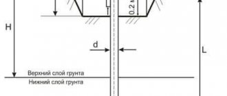
- the device must be located on a planned site at a height of at least 0.2 m from the planning level and must have a design that meets environmental conditions. In areas where snow drifts of 1 m or more in height are observed, cabinets should be installed on elevated foundations;
- Local heating must be provided to ensure normal operation of devices, relays, measuring instruments and metering devices in accordance with the requirements of state standards and other regulatory documents. Local lighting must be provided in cabinets.
Requirements for metering devices and installation locations
For the purpose of determining the volumes of consumption (production) of electrical energy (power) in retail markets, services provided for the transmission of electrical energy, actual losses of electrical energy in electric grid facilities, the readings of metering devices are used that comply with the requirements of the legislation of the Russian Federation on ensuring the uniformity of measurements, the Decree of the Government of the Russian Federation Federation dated July 17, 2015 N 719 “On confirmation of the production of industrial products on the territory of the Russian Federation” (subject to the availability of such metering devices in free access on the relevant product market), as well as requirements for the place of their installation and accuracy class that have intact control seals and (or) visual control signs approved for operation in the manner prescribed by the legislation of the Russian Federation on the electric power industry as of the date of approval. Used certified metering devices that do not meet the specified requirements can be used until the expiration of their service life or the failure of such metering devices or their loss.
From January 1, 2022, for electric energy (power) metering, metering devices must be installed that meet the requirements for electric energy metering devices that can be connected to an intelligent electric energy (power) metering system, in accordance with the rules for providing access to a minimum set of functions intelligent electrical energy (power) metering systems.
To account for consumed (produced) electrical energy, metering devices of an accuracy class that meet the requirements of the rules for providing access to the minimum set of functions of intelligent electrical energy (power) metering systems must be used, and for consumers - with a maximum power of at least 670 kW, including metering devices , providing storage of data on hourly volumes of electrical energy consumption for the last 90 days or more.
The accuracy class of instrument transformers used in measuring systems for installing (connecting) metering devices must be at least 0.5.
When installing metering devices in cases not related to technological connection, metering devices must be installed in the places specified in the documents on technological connection and (or) certificates of approval for operation of electrical energy metering devices, and it is necessary to be guided by the document (act) that was completed and signed later.
In the absence of information about the installation locations of metering devices in the documents on technological connection and (or) certificates of approval for operation of electrical energy metering devices or in the absence of the technical possibility of installing the metering device in the specified locations, unless otherwise established by agreement of the parties, the metering device must be installed on the border of the balance sheet accessories of electric power facilities (power receiving devices) of related entities.
If there is no technical possibility of installing a metering device at the border of the balance sheet, unless otherwise established by agreement of the parties, the metering device must be installed in a place as close as possible to it, in which there is a technical possibility of its installation.
It is not technically possible to install a metering device if at least one of the following conditions is met:
- installation of a metering device according to the design characteristics of the installation sites is impossible without reconstruction, major repairs of existing energy receiving devices, electrical energy (power) production facilities or electrical grid facilities and (or) without the creation of new capital construction facilities;
- When installing a metering device, it is impossible to ensure compliance with the mandatory metrological and technical requirements for the metering device, including the conditions for its installation and operation, imposed in accordance with the legislation of the Russian Federation on ensuring the uniformity of measurements and on technical regulation.
- The conditions of the absence of the technical possibility of installing a metering device do not apply to the technological connection of power receiving devices of electrical energy consumers, electrical energy production facilities, as well as electrical grid facilities belonging to network organizations and other persons to electrical networks.
If, in relation to a dilapidated and (or) emergency facility, a metering device has not previously been approved for operation, the implementation of the responsibilities of the network organization (guaranteed supplier - in relation to collective (common house) metering devices), in relation to the delivery points of such objects, is carried out no earlier than their implementation. the owner (management organization, homeowners' association, housing cooperative or other specialized consumer cooperative, and in the case of direct management of the owners of premises in an apartment building - a person engaged by the owners of premises in an apartment building under contracts for the provision of services for the maintenance and (or) performance of work on the repair of internal buildings electrical systems) reconstruction, as a result of which the circumstances causing the technical impossibility of installing a metering device will be eliminated and receiving an application from such an owner to install a metering device. A network organization has the right to install a metering device at electrical grid facilities (with the exception of collective (common house) metering devices) belonging to such network organization by right of ownership or other legal basis, with notification to the owner of the dilapidated and (or) emergency facility that there is no need to eliminate the circumstances that constitute the reason for the technical impossibility of installing a meter within the boundaries of such objects.
Meters should be located in dry rooms that are easily accessible for maintenance, in a place that is sufficiently free and not cramped for work. General industrial meters are not allowed to be installed in rooms where, due to production conditions, the temperature can often exceed +40°C, as well as in rooms with aggressive environments. It is allowed to place meters in unheated rooms and corridors of switchgears of power plants and substations, as well as in outdoor cabinets. If the devices are not intended for use in conditions of negative temperatures, they must be permanently insulated for the winter using insulating cabinets, hoods with heated air inside them with an electric lamp or heating element to ensure a positive temperature inside the hood, but not higher than +20 °C (PUE clause 1.5.27).
Meters must be installed in cabinets, chambers of complete switchgears (KRU, KRUP), on panels, switchboards, in niches, on walls with a rigid structure. The height from the floor to the meter terminal box must be in the range of 0.8-1.7 m. A height of less than 0.8 m is allowed, but not less than 0.4 m (PUE clause 1.5.29) (except for technical installation options PU at the connection point on the support of a 0.4 kV overhead line).
The designs and dimensions of cabinets, niches, panels, etc. should provide convenient access to the terminals of meters and current transformers. In addition, it must be possible to conveniently replace the meter. The design of its fastening must ensure the possibility of installing and removing the meter from the front side (PUE clause 1.5.31).
If there are several connections at the facility with separate electricity metering, the meter panels must contain inscriptions with the names of connections (PUE clause 1.5.38).